2A24I-V06G12J16Smart Sense Tag
Tag-N-Trac Inc.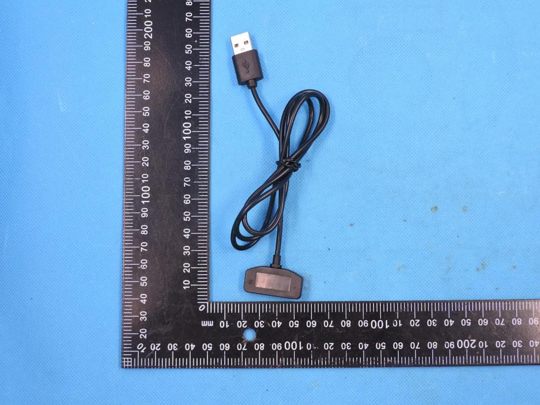
Click to zoom
Application Details
- Equipment Class
- PCB - PCS Licensed Transmitter
- Date of Grant
- Nov 09, 2022
- Application Purpose
- Original Equipment
- Date of Application
- Nov 09, 2022
- Equipment Note
- Smart Sense Tag
- Frequency Range
- 1860.00000000 - 1905.00000000
- Company
- Tag-N-Trac Inc.
- Country
- United States
Documents & Files
Document Text
Text extracted from the exhibit documents filed with the FCC. Open a document above to read the original.
Users Manual
Tag-N-Trac 4250 Executive Sq, Suite 675, La Jolla, CA 92037 www.tagntrac.com +1-858-365-5888 About This User Manual This user manual explains how to use Tag-N-Trac’s SmartSense Tag. This product is also referred to as a – cellular puck or cellular tracker. The intended audience is users who will be receiving samples of the SmartSense tag for test, evaluation, or deployment. SmartSense tag is currently in production. What is included in the box? SmartSense Tag is shipped with a charging cable. Image 1. SmartSense Tag with charging cable. USER MANUAL SmartSense Tag TAG-N-TRAC SMARTSENSE TAG Tag-N-Trac 4250 Executive Sq, Suite 675, La Jolla, CA 92037 www.tagntrac.com +1-858-365-5888 Front and back of the SmartSense Tag: Image 2. Front and Back of the SmartSense Tag. How to charge the Tag: The charging cable has a magnetic connector. Please connect the cable to the device as shown in the image below. Below images illustrate how to charge the SmartSense Tag with its charging cable. The charging cable has a magnetic connector with two pins that is used to charge the Tag. Image 3. SmartSense Tag – charging cable and charging port. Tag-N-Trac 4250 Executive Sq, Suite 675, La Jolla, CA 92037 www.tagntrac.com +1-858-365-5888 Image 4. SmartSense Tag – charging cable plugged into the charging port. MicroUSB port: MicroUSB port is not a charging port. It is available to connect any supported sensors for e.g., high precision temperature sensor with probes. LED status indicators: GREEN Charging state – with charger plugged in. RED State of the device ON Device is being charged. Blinking Device is awake - trying to get a fix or upload the data to the cloud. OFF Device is fully charged OFF Device is in sleep state. Table 1. Status of Green and Red LEDs. Wakeup button: Wakeup button is used to spontaneously wake up the device and capture latest sensor data. Note that the device will wake up, read, and store the sensor data. It will not upload it to the cloud at this time. Tag-N-Trac 4250 Executive Sq, Suite 675, La Jolla, CA 92037 www.tagntrac.com +1-858-365-5888 Tag-N-Trac customer dashboard – Understanding data uploaded by the SmartSense Tag: Data captured by the SmartSense Tag is uploaded to Tag-N-Trac’s cloud at a pre-defined interval. This data and related analytics can be visualized on Tag-N-Trac’s customer dashboard. Image 5. Tag-N-Trac Customer Dashboard More details regarding the Dashboard can be found in TNT’s Cloud User Manual. Tag-N-Trac 4250ExecutiveSq, Suite675, LaJolla, CA92037 www.tagntrac.com +1-858-365-5888 FCC Caution This device complies with part 15 of the FCC Rules. Operation is subject to the following two conditions: (1) This device may not cause harmful interference, and (2) this device must accept any interference received, including interference that may cause undesired operation. Any Changes or modifications not expressly approved by the party responsible for compliance could void the user's authority to operate the equipment. Note: This equipment has been tested and found to comply with the limits for a Class B digital device, pursuant to part 15 of the FCC Rules. These limits are designed to provide reasonable protection against harmful interference in a residential installation. This equipment generates uses and can radiate radio frequency energy and, if not installed and used in accordance with the instructions, may cause harmful interference to radio communications. However, there is no guarantee that interference will not occur in a particular installation. If this equipment does cause harmful interference to radio or television reception, which can be determined by turning the equipment off and on, the user is encouraged to try to correct the interference by one or more of the following measures: -Reorient or relocate the receiving antenna. - Increase the separation between the equipment and receiver. -Connect the equipment into an outlet on a circuit different from that to which the receiver is connected. -Consult the dealer or an experienced radio/TV technician for help. This Smart Sense Tag meets the government's requirements for exposure to radio waves. The guidelines are based on standards that were developed by independent scientific organizations through periodic and thorough evaluation of scientific studies. Thestandards include a substantial safety margin designed to assure the safety of all persons regardless of age or health. The SAR limit of USA (FCC) is 1.6 W/kg averaged over one gram of tissue. Device types: Smart Sense Tag (FCC ID: 2A24I-V06G12J16) has also been tested against this SAR limit. The highestSAR value reported under this standard during product certification for when properly worn on the body is 0.668W/kg. This device was tested for typical body-worn operations with the back of the handset kept 5mm from the body. To maintain compliance with FCC RF exposure requirements, use accessories that maintain a 5mm separation distance between the user's body and the back of the handset. The use of belt clips, holsters and similar accessories should not contain metallic components in its assembly. The use of accessories that do not satisfy these requirements may not comply with FCC RF exposure requirements, and should be avoided. Body-worn Operation This device was tested for typical body-worn operations. To comply with RF exposure requirements, a minimum separation distance of 5mm must be maintained between the user’s body and the handset, including the antenna. Third-party belt-clips, holsters, and similar accessories used by this device should not contain any metallic components. Body-worn accessories that do not meet these requirements may not comply with RF exposure requirements and should be avoided. Use only the supplied or an approved antenna. Tag-N-Trac 4250ExecutiveSq, Suite675, LaJolla, CA92037 www.tagntrac.com +1-858-365-5888 CE Maintenance 1. Risk of explosion if battery is replaced by an incorrect type. Dispose of used batteries according to…
Text truncated - open the document above for the full version.
Cover Letter(s)
Tag-N-Trac Inc. Agent Authorization Company: Tag-N-Trac Inc. Address: 4250 Executive Sq, #675, La Jolla, California, United States, 92037 Product Name: Smart Sense Tag Model Number(s): ST100 Product Description: Smart Sense Tag FCC ID: 2A24I-V06G12J16 We authorize MiCOM Labs Inc., 575 Boulder Court, Pleasanton, California 94566, USA, to act on our behalf on all matters concerning the certification of above named equipment. We declare that MiCOM Labs Inc. is allowed to forward all information related to the approval and certification of equipment to the regulatory agencies as required and to discuss any issues concerning the approval application. Any and all acts carried out by MiCOM Labs on our behalf shall have the same effect as acts of our own. Signature: Date: 2022.10.19 Name: Jiankuai Li Title: PM Company: Shenzhen STS Test Services Co., Ltd.
Cover Letter(s)
2022.08.10 Federal Communica tio ns Commis si on Authoriza tion & Eval uation Divis io n 7345 Oakla nd Mills Road Columbia, Maryland 21046 LETTER OF AGENT AUTHORIZATION To Whom It May Conc ern: We, the undersigned, hereby authorize SHENZHEN STS TEST SERVICES CO.,LTD./ A 1/F, Buildi ng B, Zhuok e Sci ence Park, No.190 Chongqing Road, HepingShequ, Fuyong Sub-District,Bao’a n Di st ric t, Shenzh en, Guang Dong, China/J iankuai Li(Name of Agent company na me and ad dress, Name of Agent) to act on our behalf i n all matters relati ng to applica tio n for equipment authoriza tio n, inc lu di ng the si gning of all documents relati ng to thes e matters . Name: Ji ankuai Li Ti tle: PM E-mail:J ia nkuai.li @stsa pp.com This appoi nt ment is v al id until f urther unti l Aug 09, 2023 Since rely, Gary Leung System HW Engin eer gary@tagntrac. co m Tag-N -Trac Inc.
Cover Letter(s)
Tag-N-Trac Inc. Office of Engineering Technology Federal Communications Commission 7435 Oakland Mills Road Columbia, MD 21046 USA Date: 2022.10.19 Subject; Request for Confidentiality FCC ID: 2A24I-V06G12J16 To Whom It May Concern, Pursuant to the provisions of the Commission’s rules Title 47 Sections §0.457 and §0.459, we are requesting the Commission to withhold the following attachment(s) as confidential documents from public disclosure indefinitely. These documents contain detailed system and equipment descriptions and are considered as proprietary information in operation of the equipment. The public disclosure of these documents might be harmful to our company and would give competitors an unfair advantage in the market. Schematic Diagram Block Diagram Operational Description Tune-up Procedure Part List SOFTWARE SECURITY REQUIREMENTS FOR U-NII DEVICES In additional to above mentioned documents, in order to comply with the marketing regulations in Title 47 CFR §2.803 and the importation rules in Title 47 CFR §2.1204, while ensuring that business sensitive information remains confidential until the actual marketing of newly authorized devices, we request Short Term Confidentiality of the following attachment(s); External Photos Test Setup Photos Internal Photos User Manual For 45 days, pursuant to Public Notice DA 04-1705. OR For 180 days pursuant to KDB 726920 D01. It is our understanding that all measurement test reports, FCC ID label format and correspondence during the certification review process cannot be granted as confidential documents and this information will be available for public review once the grant of equipment authorization is issued. Sincerely, Signature: Name: Jiankuai Li Title: PM
Cover Letter(s)
FCC Software Configuration Control Declaration Rev1.1 Tag-N-Trac Inc. FCC Software Configuration Control Declaration Date: 2022.10.19 Federal Communications Commission 7435 Oakland Mills Road Columbia, MD 21046 USA Attn: Tag-N-Trac Inc. Product Name: Smart Sense Tag Model Number(s): ST100 FCC ID: 2A24I-V06G12J16 Regarding FCC Country Code Selection guidelines identified in KDB 594280. “All applications for equipment authorization for transmitters that can have radio parameters, or other technical parameters, reported to the Commission set by software must have an attestation indicating that no third party will have software, or configuration control, to program the device out of compliance of the technical rules under which it has been certified.” We declare that no third party will have software, or configuration control, to program the device out of compliance of the technical rules under which it has been certified. Name: Jiankuai Li Date: 2022.10.19 Title: PM Signature of applicant
External Photos
Page 1 of 4 Report No.: STS2206143 APPENDIX-PHOTOGRAPHS OF EUT CONSTRUCTIONAL DETAILS Photo 1 Photo 2 Page 2 of 4 Report No.: STS2206143 Photo 3 Photo 4 Page 3 of 4 Report No.: STS2206143 Photo 5 Photo 6 Page 4 of 4 Report No.: STS2206143 Photo 7 Photo 8
ID Label/Location Info
Model: ST100 DESIGNED BY Tag-N-Trac, Inc. FCC ID: 2A24I-V06G12J16 Internal Battery: 280mAh 3.7V Operating Voltage: DC 5V This device complies with Part 15 of FCC rules. Operation is subject to the following two conditions: (1) This device may not cause harmful interferences,and (2) This device must accept any interference received, Including interference that may cause undersired operation Model: ST100 DESIGNED BY Tag-N-Trac, Inc. FCC ID: 2A24I-V06G12J16 Internal Battery: 280mAh 3.7V Operating Voltage: DC 5V This device complies with Part 15 of FCC rules. Operation is subject to the following two conditions: (1) This device may not cause harmful interferences,and (2) This device must accept any interference received, Including interference that may cause undersired operation
Internal Photos
Page 1 of 3 Report No.: STS2206143 APPENDIX-PHOTOGRAPHS OF EUT CONSTRUCTIONAL DETAILS Photo 1 Photo 2 GPS Antenna LTE CAT M Antenna Page 2 of 3 Report No.: STS2206143 Photo 3 Photo 4 Page 3 of 3 Report No.: STS2206143 Photo 5 Photo 6
RF Exposure Info
Ref : ACR.262.4.20.MVGB.A SHENZHEN STS TEST SERVICES CO., LTD. 1/F., BUILDING 2, ZHUOKE SCIENCE PARK,No.190, CHONGQING ROAD,FUYONG STREET, BAO’ AN DISTRICT, SHENZHEN,GUANGDONG,CHINA MVG COMOSAR REFERENCE DIPOLE FREQUENCY: 750 MHZ SERIAL NO.: SN 30/14 DIP0G750-331 SAR Reference Dipole Calibration Report Calibrated at MVG Z.I. de la pointe du diable Technopôle Brest Iroise - 295 avenue Alexis de Rochon 29280 PLOUZANE - FRANCE Calibration date: 07/14/2020 Summary: This document presents the method and results from an accredited SAR reference dipole calibration performed in MVG. using the CALIPROBE test bench. for use with a MVG COMOSAR system only. The test results covered by accreditation are traceable to the International System of Units(SI). Page: 1/11 SAR REFERENCE DIPOLE CALIBRATION REPORT Ref: ACR.262.4.20.MVGB.A Customer Name Distribution : Shenzhen STS Test Services Co., Ltd. Name Function Date Signature Prepared by : Jérôme LUC Technical Manager 7/28/2020 Checked by : Jérôme LUC Technical Manager 7/28/2020 Approved by : Yann Toutain Laboratory Director 7/28/2020 Issue Date Modifications A 7/28/2020Initial release Name Jérôme LUC Page: 2/11 Template_ACR.DDD.N.YY.MVGB.ISSUE_COMOSAR Dipole vH This document shall not be reproduced, except in full or in part, without the written approval of MVG. The information contained herein is to be used only for the purpose for which it is submitted and is not to be released in whole or part without written approval of MVG. SAR REFERENCE DIPOLE CALIBRATION REPORT Ref: ACR.262.4. TABLE OF CONTENTS 1 Introduction ................................................................................................................ 4 2 Device Under Test ..................................................................................................... 4 3 Product Description ................................................................................................... 4 3.1 General Information _______________________________________________________ 4 4 Measurement Method ................................................................................................ 5 4.1 Return Loss Requirements __________________________________________________ 5 4.2 Mechanical Requirements ___________________________________________________ 5 5 Measurement Uncertainty .......................................................................................... 5 5.1 Return Loss ______________________________________________________________ 5 5.2 Dimension Measurement ___________________________________________________ 5 5.3 Validation Measurement ____________________________________________________ 5 6 Calibration Measurement Results .............................................................................. 6 6.1 Return Loss and Impedance In Head Liquid ____________________________________ 6 6.2 Return Loss and Impedance In Body Liquid ____________________________________ 6 6.3 Mechanical Dimensions ____________________________________________________ 6 7 Validation measurement ............................................................................................ 7 7.1 Head Liquid Measurement __________________________________________________ 7 7.2 SAR Measurement Result With Head Liquid ____________________________________ 8 7.3 Body Liquid Measurement __________________________________________________ 9 7.4 SAR Measurement Result With Body Liquid __________________________________ 10 8 List of Equipment .................................................................................................... 11 Page: 3/11 This document shall not be reproduced, except in full or in part, without the written approval of MVG. The information contained herein is to be used only for the purpose for which it is submitted and is not to be released in whole or part without written approval of MVG. MVGB.A 20. Template_ACR.DDD.N.YY.MVGB.ISSUE_COMOSAR Dipole vH SAR REFERENCE DIPOLE CALIBRATION REPORT Ref: ACR.262.4.20.MVGB.A 1 INTRODUCTION This document contains a summary of the requirements set forth by the IEEE 1528, OET 65 Bulletin C and CEI/IEC 62209 standards for reference dipoles used for SAR measurement system validations and the measurements that were performed to verify that the product complies with the fore mentioned standards. 2 DEVICE UNDER TEST Device Under Test Device Type COMOSAR 750 MHz REFERENCE DIPOLE Manufacturer MVG Model SID750 Serial Number SN 30/14 DIP0G750-331 Product Condition (new / used) Used A yearly calibration interval is recommended. 3 PRODUCT DESCRIPTION 3.1 GENERAL INFORMATION MVG’s COMOSAR Validation Dipoles are built in accordance to the IEEE 1528, OET 65 Bulletin C and CEI/IEC 62209 standards. The product is designed for use with the COMOSAR test bench only. Figure 1 – MVG COMOSAR Validation Dipole Page: 4/11 This document shall not be reproduced, except in full or in part, without the written approval of MVG. The information contained herein is to be used only for the purpose for which it is submitted and is not to be released in whole or part without written approval of MVG. Template_ACR.DDD.N.YY.MVGB.ISSUE_COMOSAR Dipole vH SAR REFERENCE DIPOLE CALIBRATION REPORT Ref: ACR.262.4.20.MVGB.A 4 MEASUREMENT METHOD The IEEE 1528, OET 65 Bulletin C and CEI/IEC 62209 standards provide requirements for reference dipoles used for system validation measurements. The following measurements were performed to verify that the product complies with the fore mentioned standards. 4.1 RETURN LOSS REQUIREMENTS The dipole used for SAR system validation measurements and checks must have a return loss of -20 dB or better. The return loss measurement shall be performed against a liquid filled flat phantom, with the phantom constucted as outlined in the fore mentioned standards. 4.2 MECHANICAL REQUIREMENTS The IEEE Std. 1528 and CEI/IEC 62209 standards specify the mechanical components and dimensions of the validation dipoles, with the dimensions frequency an…
Text truncated - open the document above for the full version.
RF Exposure Info
Any reproduction of this document must be done in full. No single part of this document may be reproduced without permission from STS, All Test Data Presented in this report is only applicable to presented Test sample. ShenZhen STS Test Services Co.,Ltd. A 1/F, Building B, Zhuoke Science Park, No.190 Chongqing Road, HepingShequ, Fuyong Sub-District, Bao’an District, Shenzhen, Guang Dong, China TEL: +86-755 3688 6288 FAX: +86-755 3688 6277 E-mail:[email protected] FCC SAR TEST REPORT Report No.: STS2206143H01 Issued for Tag-N-Trac Inc. 4250 Executive Sq, #675, La Jolla, California, United States, 92037 Product Name: Smart Sense Tag Brand Name: TAG-N-TRAC Model Name: ST100 Series Model: N/A FCC ID: 2A24I-V06G12J16 Test Standard: ANSI/IEEE Std. C95.1 FCC 47 CFR Part 2 ( 2.1093) IEEE 1528: 2013 Max. Report SAR (1g): Body: 0.668 W/kg S T L A B S Page 2 of 41 Report No.: STS2206143H01 Test Report Certification Applicant’s name ................. : Tag-N-Trac Inc. Address ................................. : 4250 Executive Sq, #675, La Jolla, California, United States, 92037 Manufacturer's Name .......... : Chongqing Huiye IoT Technology Co.,Ltd. Address ................................. : FL.5, Haibo Building 2, No.829, Yishan Rd, Xuhui, Shanghai. 200233 Product description Product name ........................ : Smart Sense Tag Brand name ......................... : TAG-N-TRAC Model name ......................... : ST100 Series Model .......................... : N/A Standards ............................. : ANSI/IEEE Std. C95.1-1992 FCC 47 CFR Part 2 ( 2.1093) IEEE 1528: 2013 The device was tested by Shenzhen STS Test Services Co., Ltd. in accordance with the measurement methods and procedures specified in KDB 865664 The test results in this report apply only to the tested sample of the stated device/equipment. Other similar device/equipment will not necessarily produce the same results due to production tolerance and measurement uncertainties. Date of Test ........................................... : Date (s) of performance of tests ............. : 04 Aug. 2022 Date of Issue .......................................... : 08 Aug. 2022 Test Result.............................................. : Pass Testing Engineer : (Shifan. Long) Technical Manager : (Sean she) Authorized Signatory : (Bovey Yang) Page 3 of 41 Report No.: STS2206143H01 Table of Contents 1. General Information 5 1.1 EUT Description 5 1.2 Test Environment 6 1.3 Test Factory 6 2. Test Standards and Limits 7 3. SAR Measurement System 8 3.1 Definition of Specific Absorption Rate (SAR) 8 3.2 SAR System 8 4. Tissue Simulating Liquids 11 4.1 Simulating Liquids Parameter Check 11 5. SAR System Validation 13 5.1 Validation System 13 5.2 Validation Result 13 6. SAR Evaluation Procedures 14 7. EUT Test Position 15 7.1 Body-worn Position Conditions 15 8. Uncertainty 16 8.1 Measurement Uncertainty 16 9. Conducted Power Measurement 17 9.1 Test Result 17 10. EUT and Test Setup Photo 22 10.1 EUT Photo 22 10.2 Setup Photo 25 11. SAR Result Summary 26 11.1 Body-worn SAR 26 12. Equipment List 27 Appendix A. System Validation Plots 28 Appendix B. SAR Test Plots 36 Appendix C. Probe Calibration and Dipole Calibration Report 41 Page 4 of 41 Report No.: STS2206143H01 Revision History Rev. Issue Date Report No. Effect Page Contents 00 08 Aug. 2022 STS2206143H01 ALL Initial Issue Page 5 of 41 Report No.: STS2206143H01 1. General Information Environmental evaluation measurements of specific absorption rate (SAR) distributions in emulated human head and body tissues exposed to radio frequency (RF) radiation from wireless portable devices for compliance with the rules and regulations of the U.S. Federal Communications Commission (FCC). 1.1 EUT Description Product Name Smart Sense Tag Brand Name TAG-N-TRAC Model Name ST100 Series Model N/A Model Difference N/A Battery Rated Voltage: 3.7V Charge Limit Voltage: 4.2V Capacity: 280mAh Device Category Portable Product stage Production unit RF Exposure Environment General Population / Uncontrolled Hardware Version QHY003_V1.03 Software Version MCU_02_02_00_00_11751_APP_01_00_LO Frequency Range CAT-M Band 2:1850~1910MHz CAT-M Band 4:1710~1755MHz CAT-M Band 12:699~716MHz CAT-M Band 13:777~787MHz CAT-M Band 25:1850~1915MHz Max. Reported SAR(1g): (Limit:1.6W/kg) Band Mode Body Worn (W/kg) PCB CAT-M FDD Band 2 0.582 PCB CAT-M FDD Band 4 0.668 PCB CAT-M FDD Band 12 0.348 PCB CAT-M FDD Band 13 0.387 PCB CAT-M FDD Band 25 0.553 FCC Equipment Class PCS Licensed Transmitter (PCB) Operating Mode: CAT-M Band: QPSK, 16QAM Antenna Specification: CAT-M Band: Monopole Antenna SIM Card Built-in card. DTM Mode Not Support Note: 1. The EUT battery must be fully charged and checked periodically during the test to ascertain uniform power Page 6 of 41 Report No.: STS2206143H01 1.2 Test Environment Ambient conditions in the SAR laboratory: Items Required Temperature (°C) 18-25 Humidity (%RH) 30-70 1.3 Test Factory ShenZhen STS Test Services Co.,Ltd. A 1/F, Building B, Zhuoke Science Park, No.190 Chongqing Road, HepingShequ, Fuyong Sub- District, Bao’an District, Shenzhen, Guang Dong, China FCC test Firm Registration No.: 625569 IC Registration No.: 12108A A2LA Certificate No.: 4338.01 Page 7 of 41 Report No.: STS2206143H01 2. Test Standards and Limits No. Identity Document Title 1 47 CFR Part 2 Frequency Allocations and Radio Treaty Matters; General Rules and Regulations 2 ANSI/IEEE Std. C95.1-1992 IEEE Standard for Safety Levels with Respect to Human Exposure to Radio Frequency Electromagnetic Fields, 3 kHz to 300 GHz 3 IEEE Std. 1528-2013 Recommended Practice for Determining the Peak Spatial- Average Specific Absorption Rate (SAR) in the Human Head from Wireless Communications Devices: Measurement Techniques 4 FCC KDB 447498 D04 v01 RF Exposure Procedures and Equipment Authorization Policies for Mobile and Portable Devices 5 FCC KDB 865664 D01 v01r04 SAR Measurement 100 MHz to 6 GHz 6 FCC KDB 865664 D02 v01r02 RF Exposure Reporting 7 FCC…
Text truncated - open the document above for the full version.
Test Report
2A24I-V06G12J16_SAR Setup photos Body Front side(separation distance is 5mm) Body Back side(separation distance is 5mm)
Test Report
Report No: STS2206143W01_Appendix CAT-M 03 Peak-to-Average Ratio Band Bandwidth (MHz) UL Channel RB Size RB Position NB Index Modulation Result (dB) high Limit (dB) Verdict Band2 1.4 18900 6 #0 0 QPSK 11.31 13 PASS Band2 1.4 18900 5 #0 0 QAM16 11.65 13 PASS Band2 3 18900 6 #0 0 QPSK 11.39 13 PASS Band2 3 18900 5 #0 0 QAM16 11.51 13 PASS Band2 5 18900 6 #0 0 QPSK 11.44 13 PASS Band2 5 18900 5 #0 0 QAM16 11.08 13 PASS Band2 10 18900 6 #0 0 QPSK 12.81 13 PASS Band2 10 18900 5 #0 0 QAM16 12.41 13 PASS Band2 15 18900 6 #0 0 QPSK 9.14 13 PASS Band2 15 18900 5 #0 0 QAM16 12.43 13 PASS Band2 20 18900 6 #0 0 QPSK 9.45 13 PASS Band2 20 18900 5 #0 0 QAM16 10.09 13 PASS Band4 1.4 20175 6 #0 0 QPSK 9.17 13 PASS Band4 1.4 20175 5 #0 0 QAM16 11.40 13 PASS Band4 3 20175 6 #0 0 QPSK 11.78 13 PASS Band4 3 20175 5 #0 0 QAM16 12.91 13 PASS Band4 5 20175 6 #0 0 QPSK 10.70 13 PASS Band4 5 20175 5 #0 0 QAM16 11.57 13 PASS Band4 10 20175 6 #0 0 QPSK 11.88 13 PASS Band4 10 20175 5 #0 0 QAM16 11.67 13 PASS Band4 15 20175 6 #0 0 QPSK 9.19 13 PASS Band4 15 20175 5 #0 0 QAM16 9.81 13 PASS Band4 20 20175 6 #0 0 QPSK 9.36 13 PASS Band4 20 20175 5 #0 0 QAM16 11.45 13 PASS Band12 1.4 23095 6 #0 0 QPSK 9.60 13 PASS Band12 1.4 23095 5 #0 0 QAM16 12.36 13 PASS Band12 3 23095 6 #0 0 QPSK 11.15 13 PASS Band12 3 23095 5 #0 0 QAM16 11.28 13 PASS Band12 5 23095 6 #0 0 QPSK 9.32 13 PASS Band12 5 23095 5 #0 0 QAM16 10.13 13 PASS Band12 10 23095 6 #0 0 QPSK 11.22 13 PASS Band12 10 23095 5 #0 0 QAM16 9.90 13 PASS Band13 5 23230 6 #0 0 QPSK 9.07 13 PASS Band13 5 23230 5 #0 0 QAM16 11.85 13 PASS Band13 10 23230 6 #0 0 QPSK 9.50 13 PASS Band13 10 23230 5 #0 0 QAM16 9.82 13 PASS Band25 1.4 26365 6 #0 0 QPSK 9.63 13 PASS Band25 1.4 26365 5 #0 0 QAM16 11.76 13 PASS Band25 3 26365 6 #0 0 QPSK 11.25 13 PASS Band25 3 26365 5 #0 0 QAM16 10.72 13 PASS Report No: STS2206143W01_Appendix CAT-M Band25 5 26365 6 #0 0 QPSK 9.64 13 PASS Band25 5 26365 5 #0 0 QAM16 11.41 13 PASS Band25 10 26365 6 #0 0 QPSK 12.20 13 PASS Band25 10 26365 5 #0 0 QAM16 10.62 13 PASS Band25 15 26365 6 #0 0 QPSK 8.91 13 PASS Band25 15 26365 5 #0 0 QAM16 11.21 13 PASS Band25 20 26365 6 #0 0 QPSK 10.52 13 PASS Band25 20 26365 5 #0 0 QAM16 12.56 13 PASS Band2 QAM16 BW=15MHz Channel=18900 RB Size=5 Position=#0 NB Index=0 Band2 QAM16 BW=1.4MHz Channel=18900 RB Size=5 Position=#0 NB Index=0 Report No: STS2206143W01_Appendix CAT-M Band2 QAM16 BW=10MHz Channel=18900 RB Size=5 Position=#0 NB Index=0 Band2 QAM16 BW=20MHz Channel=18900 RB Size=5 Position=#0 NB Index=0 Report No: STS2206143W01_Appendix CAT-M Band2 QAM16 BW=3MHz Channel=18900 RB Size=5 Position=#0 NB Index=0 Band2 QAM16 BW=5MHz Channel=18900 RB Size=5 Position=#0 NB Index=0 Report No: STS2206143W01_Appendix CAT-M Band2 QPSK BW=1.4MHz Channel=18900 RB Size=6 Position=#0 NB Index=0 Band2 QPSK BW=10MHz Channel=18900 RB Size=6 Position=#0 NB Index=0 Report No: STS2206143W01_Appendix CAT-M Band2 QPSK BW=15MHz Channel=18900 RB Size=6 Position=#0 NB Index=0 Band2 QPSK BW=20MHz Channel=18900 RB Size=6 Position=#0 NB Index=0 Report No: STS2206143W01_Appendix CAT-M Band2 QPSK BW=3MHz Channel=18900 RB Size=6 Position=#0 NB Index=0 Band2 QPSK BW=5MHz Channel=18900 RB Size=6 Position=#0 NB Index=0 Report No: STS2206143W01_Appendix CAT-M Band4 QAM16 BW=3MHz Channel=20175 RB Size=5 Position=#0 NB Index=0 Band4 QAM16 BW=1.4MHz Channel=20175 RB Size=5 Position=#0 NB Index=0 Report No: STS2206143W01_Appendix CAT-M Band4 QAM16 BW=10MHz Channel=20175 RB Size=5 Position=#0 NB Index=0 Band4 QAM16 BW=15MHz Channel=20175 RB Size=5 Position=#0 NB Index=0 Report No: STS2206143W01_Appendix CAT-M Band4 QAM16 BW=20MHz Channel=20175 RB Size=5 Position=#0 NB Index=0 Band4 QAM16 BW=5MHz Channel=20175 RB Size=5 Position=#0 NB Index=0 Report No: STS2206143W01_Appendix CAT-M Band4 QPSK BW=1.4MHz Channel=20175 RB Size=6 Position=#0 NB Index=0 Band4 QPSK BW=10MHz Channel=20175 RB Size=6 Position=#0 NB Index=0 Report No: STS2206143W01_Appendix CAT-M Band4 QPSK BW=15MHz Channel=20175 RB Size=6 Position=#0 NB Index=0 Band4 QPSK BW=20MHz Channel=20175 RB Size=6 Position=#0 NB Index=0 Report No: STS2206143W01_Appendix CAT-M Band4 QPSK BW=3MHz Channel=20175 RB Size=6 Position=#0 NB Index=0 Band4 QPSK BW=5MHz Channel=20175 RB Size=6 Position=#0 NB Index=0 Report No: STS2206143W01_Appendix CAT-M Band12 QAM16 BW=1.4MHz Channel=23095 RB Size=5 Position=#0 NB Index=0 Band12 QAM16 BW=10MHz Channel=23095 RB Size=5 Position=#0 NB Index=0 Report No: STS2206143W01_Appendix CAT-M Band12 QAM16 BW=3MHz Channel=23095 RB Size=5 Position=#0 NB Index=0 Band12 QAM16 BW=5MHz Channel=23095 RB Size=5 Position=#0 NB Index=0 Report No: STS2206143W01_Appendix CAT-M Band12 QPSK BW=1.4MHz Channel=23095 RB Size=6 Position=#0 NB Index=0 Band12 QPSK BW=10MHz Channel=23095 RB Size=6 Position=#0 NB Index=0 Report No: STS2206143W01_Appendix CAT-M Band12 QPSK BW=3MHz Channel=23095 RB Size=6 Position=#0 NB Index=0 Band12 QPSK BW=5MHz Channel=23095 RB Size=6 Position=#0 NB Index=0 Report No: STS2206143W01_Appendix CAT-M Band13 QAM16 BW=10MHz Channel=23230 RB Size=5 Position=#0 NB Index=0 Band13 QAM16 BW=5MHz Channel=23230 RB Size=5 Position=#0 NB Index=0 Report No: STS2206143W01_Appendix CAT-M Band13 QPSK BW=10MHz Channel=23230 RB Size=6 Position=#0 NB Index=0 Band13 QPSK BW=5MHz Channel=23230 RB Size=6 Position=#0 NB Index=0 Report No: STS2206143W01_Appendix CAT-M Band25 QAM16 BW=20MHz Channel=26365 RB Size=5 Position=#0 NB Index=0 Band25 QAM16 BW=1.4MHz Channel=26365 RB Size=5 Position=#0 NB Index=0 Report No: STS2206143W01_Appendix CAT-M Band25 QAM16 BW=10MHz Channel=26365 RB Size=5 Position=#0 NB Index=0 Band25 QAM16 BW=15MHz Channel=26365 RB Size=5 Position=#0 NB Index=0 Report No: STS2206143W01_Appendix CAT-M Band25 QAM16 BW=3MHz Channel=26365 RB Size=5 Position=#0 NB Index=0 Band25 QAM16 BW=5MHz Channel=26365 RB Size=5 Position=#0 NB Index=0 Report No: STS2206143W01_Appendix CAT-M Band25 QPSK BW=1.4MHz Channel=26365 RB Size=6 Position=#0 NB Index=0 Band25 QPSK BW=10MHz Channel=26365 RB Si…
Text truncated - open the document above for the full version.
Test Report
Report No: STS2206143W01_Appendix CAT-M Band2 QAM16 BW=20MHz Channel=19100 RB Size=1 Position=#Max NB Index=15 Band2 QAM16 BW=20MHz Channel=19100 RB Siz…
Text truncated - open the document above for the full version.
Contact Information
Applicant
Gary Leung(System HW Engineer)
Technical Contact
Test Firm
SHENZHEN STS TEST SERVICES CO.,LTD.Bovey Yang
[email protected]+86 755-36886288
Technical Specifications
| # | Rule Parts | Frequency Range | Power Output | Emission | Tolerance |
|---|---|---|---|---|---|
| 1 | 24E | 1.86 GHz - 1.91 GHz | 248.30 mW | 1M33W7D | 0.019 ppm |
Other Applications from Tag-N-Trac Inc.
2A24I-V02G15J18
Mar 31, 2024Sense Stream Tag - Single Use
Equipment Class
PCB - PCS Licensed Transmitter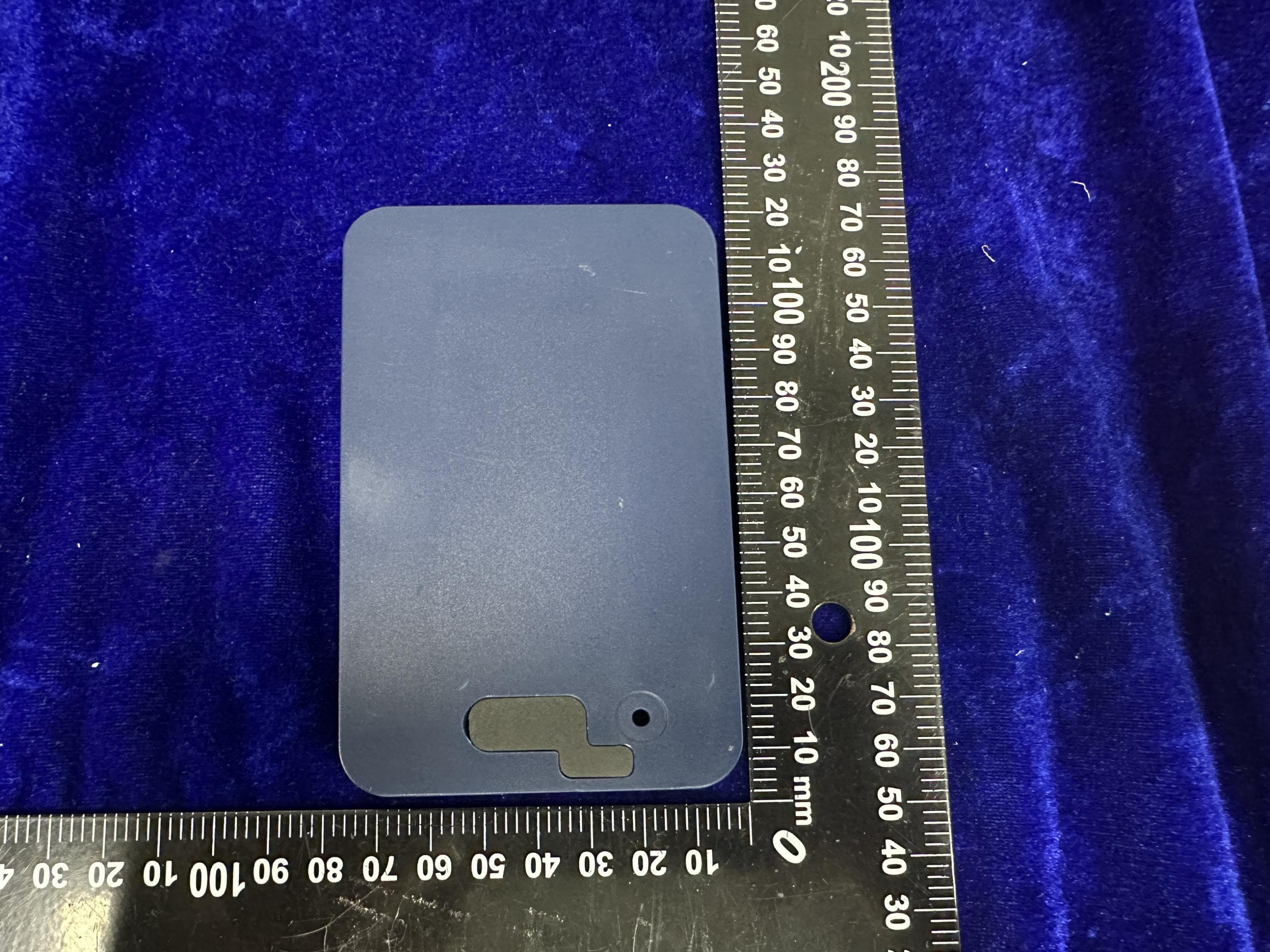
2A24I-V08G08J17
Sep 05, 2023Smart Sense Tag
Equipment Class
JAB - Part 15 Class B Digital Device
2A24I-V07G0BJ17
Sep 03, 2023SmartSense Label
Equipment Class
PCB - PCS Licensed Transmitter