2A25O-P30Wireless Massage Pads
Deen Smart LLC.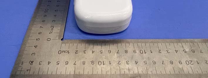
Click to zoom
Application Details
- Equipment Class
- DSC - Part 15 Security/Remote Control Transmitter
- Date of Grant
- Dec 15, 2022
- Application Purpose
- Original Equipment
- Date of Application
- Dec 15, 2022
- Equipment Note
- Wireless Massage Pads
- Frequency Range
- 433.85000000 - 433.85000000
- Company
- Deen Smart LLC.
- Country
- United States
Documents & Files
Document Text
Text extracted from the exhibit documents filed with the FCC. Open a document above to read the original.
Users Manual
USER MANUAL Wireless Massage Pads P30 Wireless Massage Pads Product Descriptions Massage Plate & Pad Compartment Mode / Intensity /Battery Level Display Charging Compartment Intensity Adjustment /Pause Knob Mode Adjustment / Turn Off Knob justment / Turn Off Knob Mode Adj On / Off Button Massage Pad Massage Button Package Content 1 x P30 Wireless Massage Pads (120*79*39 mm)2 x Massage Button4 x Massage Pad (100*50 mm) 1 x Massage Pad Storage Plate1 x USB Cable 1 x User Manual Mode Descriptions m en t s tment / ad M o d e Descr iptio ns Mode 1Mode 2Mode 3Mode 4Mode 5Mode 6 Body MassageUsed for daily relaxation, this massage helps to relieve fatigue and refresh the body. Neck Massage Used for neck health massage, this massage improves blood circulation in the neck and relieves stiffness and discomfort. Shoulder Massage Used for shoulder relaxation, this massage helps to relieve shoulder numbness and discomfort. Waist Massage Used for waist relief, this massage technique can relieve soreness, numbness, and discomfort in the waist. Limb MassageUsed for hand and foot muscle stimulation, this rhythmic massage technique can relieve muscle fatigue after exercise. Joint MassageDeep tissue massage is used for joints, this massage helps relieve joint discomfort . About This Product Thank you for purchasing our Wireless Massage Pads. This is a s tylish and innovative massage solution, with multiple modes and intensities, that offers a convenient portab le and wireless operation. It has a built-in high-quality ultra-long standby lithium battery, using Electric al Muscle Stimulation (EMS) and Transcutaneous Electrical Nerve Stimulation (TENS) technology; the integrated design of the charging case has multiple functions, including remote controls for the selection of modes and intensity, along with built-in storage compartments for the massage pads and wireless charging; with t he convenience of portability in a sleek and modern case.The Wireless Massage Pads include various modes for personal ma ssaging techniques, they can promote local blood flow, and effectively relieve fatigue, stiffness, n umbness, soreness, and other discomforts of the body’s neck, shoulder, back, limbs, and joints. Our Wireless Massage Pads can meet different needs of different people, including daily health care, working fatigue care, and muscle relaxation after exercise, which is wo rth of choice due to its value proposition. Use our Wireless Massage Pads anytime, anywhere, whenever you want them , and use them freely to take care of your body and health. Product Features 1. Massage Pads, multi-function integrated design, utilizing wi reless remote control technology, high definition display, knob control operation, simple, easy, and convenie nt to use. 2. The massage pads control case has both, storage and charging functions, each Pad has independent and automatic charging, with a long battery life that will secu re constant operation. 3. Equipped with dual buttons, massage different areas at the s ame time. Storage of plate and pads, a user-friendly way.4. Professional massage techniques, using 6 different modes and a 10-level of intensity adjustments. Operation Instructions 1. Open the box, take out the massage pads, place them horizont ally, and align the position to connecting the pins on the massage button, it will just fit through a magn etic connection, and then tear off the transparent protective film on the massage pads. g,j gg , v e f ilm on the massa g e pads. rotect iv 2. Use a clean slightly wet towel (damp but not dripping water) , and wipe off the sweat on the skin surface where the pads will be placed. gy ( p h ere the pads will be placed . 3. Stick the massage pads firmly on the skin, and long press th e switch button in the middle of the massage button to turn it on; when it is turn on, the buzzer will h ave prompt tone sounds and the indicator will light up. After turning it on, if the massage button detects that the massage pad is not making direct contact, the massage button will turned off after five beeps, entering i nto the power-saving mode. assa g e button will turned o ff a f ter f ive beeps, enterin g into the power-savin g mode . 4. The massage pads can be affixed to different parts of the bo dy respectively, and they can be operated and controlled simultaneously by the wireless remote control to achieve a synchronized massage. assage pads can be affixed to different parts of the body respectively , and they can be ope led simultaneousl y b y the wireless remote control to achieve a s y nchronized m assage. 5. When opening the control box it will be in standby mode; the operation panel lights up in default mode, and the power indicator is turned on; if the control box light flashes, it indicates low power mode and it will need to be charged. The mode and intensity knobs on the operation p anel are adjusted with a buzzer sound to freely s elect the massage mode (1-6) and massage intensity ( 01-10 ). E ach mode has 15 minutes of operation, and after that, it will automatically be turned off. charged . The mode and intensity k e ct the massa g e mode ( 1-6 ) and m r that, it will automaticall y be turn e A. The mode knob, increase the intensity clockwise, decreases t he mode counterclockwise, increases or decreases the mode step by step, there are 6 modes in total . When adjusting to mode 6 or mode 1, the user re-adjusting the knob will be invalid with an invalid promp t sound; generally adjusted each time, the buzzer prompt once with the rotate knob. The mode knob, press up and d own, also has the function of shutdown to stop dual pads massaging simultaneously for convenience. Product Information Please visit our website and social networks for more information about our Wireless MassagePads: www.deen-smart.comwww.facebook.com/deensmtwww.instagram.com/deensmt Contact information You can also contact us via email with any other product inquiry [email protected] B. The intensity knob, increase t…
Text truncated - open the document above for the full version.
External Photos
FCC ID: 2A25O-P30 TB-RF-074-1.0 Appendix III EUT External Photographs Photo 1 Appearance of EUT Photo 2 Appearance of EUT FCC ID: 2A25O-P30 TB-RF-074-1.0 Photo 3 Appearance of EUT Photo 4 Appearance of EUT FCC ID: 2A25O-P30 TB-RF-074-1.0 Photo 5 Appearance of EUT Photo 6 Appearance of EUT FCC ID: 2A25O-P30 TB-RF-074-1.0 Photo 7 Appearance of EUT Photo 8 Appearance of EUT Receiving unit FCC ID: 2A25O-P30 TB-RF-074-1.0 Photo 9 Appearance of EUT
ID Label/Location Info
FCC ID: 2A25O-P30 TB-RF-074-1.0 Appendix IFCC ID Label FCC ID: 2A25O-P30 TB-RF-074-1.0 Appendix II ID Label Location ID LOCATION
Internal Photos
FCC ID: 2A25O-P30 TB-RF-074-1.0 Appendix IV EUT Internal Photographs Photo 10 Internal of EUT Photo 11 Battery parameters FCC ID: 2A25O-P30 TB-RF-074-1.0 Photo 12 Appearance of PCB Photo 13 Appearance of PCB TX Antenna FCC ID: 2A25O-P30 TB-RF-074-1.0 Photo 14 Appearance of PCB Photo 15 Appearance of PCB
Test Report
Antenna Specification Introduction This document describes a PCB antenna design, this is a compact,low cost and high perfprmance antenna. ITEM ANT SPEC Model Name 433 ANT Center Frequency Horizontal Vertical 400MHz 425MHz 450MHz 400MHz 425MHz 450MHz 1.04dbi 1.16dBi 1.20dBi 0.835dBi 0.96dBi 1.03dBi MAX. Gain 1.20dBi Polarization Horizontal and Vertical Azimuth Beam Pattern Omni-directional Impedance 50 Ohm Antenna Length 60.00mm Antenna Photo Antenna Specification mm ANTENNA TEST RESULT Antenna Specification Manufacturer: Shenzhen Zhuoqun Century Electronics Co., Ltd; Address: 5A, Building 205, Shangbu Industrial Zone, Futian District, Shenzhen China; Email: [email protected]
Test Report
Shenzhen Toby Technology Co., Ltd. Report No.: TBR-C-202211-0077-12 Page: 1 of 33 TB-RF-074-1.0 1/F.,Building 6, Rundongsheng Industrial Zone, Longzhu, Xixiang, Bao'an District, Shenzhen, Guangdong, China Tel: +86 75526509301 Fax: +86 75526509195 FCC Radio Test Report FCC ID: 2A25O-P30 Report No. : TBR-C-202211-0077-12 Applicant : Deen Smart LLC. Equipment Under Test (EUT) EUT Name : Wireless Massage Pads Model No. : P30 Series Model No. : ---- Brand Name : Sample ID : 202211-0077-9-1#& 202211-0077-9-2# Receipt Date : 2022-11-21 Test Date : 2022-11-21 to 2022-12-14 Issue Date : 2022-12-15 Standards : FCC Part 15, Subpart C (15.231(a)) Test Method : ANSI C63.10:2013 Conclusions : PASS In the configuration tested, the EUT complied with the standards specified above, The EUT technically complies with the FCC requirements Test/Witness Engineer : Seven Wu Engineer Supervisor : Ivan Su Engineer Manager : Ray Lai This report details the results of the testing carried out on one sample. The results contained in this test report do not relate to other samples of the same product. The manufacturer should ensure that all products in series production are in conformity with the product sample detailed in the report. Report No.: TBR-C-202211-0077-12 Page: 2 of 33 TB-RF-074-1.0 Contents CONTENTS ............................................................................................................................................. 2 1. GENERAL INFORMATION ABOUT EUT ............................................................................. 5 1.1 Client Information ................................................................................................................. 5 1.2 General Description of EUT (Equipment Under Test) ................................................... 5 1.3 Block Diagram Showing the Configuration of System Tested ...................................... 6 1.4 Description of Support Units .............................................................................................. 6 1.5 Description of Test Mode .................................................................................................... 6 1.6 Description of Test Software Setting .............................................................................. 7 1.7 Measurement Uncertainty ................................................................................................ 7 1.8 Test Facility ........................................................................................................................ 8 2. TEST SUMMARY ....................................................................................................................... 9 3. TEST SOFTWARE ..................................................................................................................... 9 4. TEST EQUIPMENT .................................................................................................................. 10 5. CONDUCTED EMISSION TEST ........................................................................................... 12 5.1 Test Standard and Limit .................................................................................................... 12 5.2 Test Setup ........................................................................................................................... 12 5.3 Test Procedure ................................................................................................................... 13 5.4 Deviation From Test Standard ......................................................................................... 13 5.5 Test Data ............................................................................................................................. 13 6. RADIATED EMISSION TEST ................................................................................................ 14 6.1 Test Standard and Limit .................................................................................................... 14 6.2 Test Setup ........................................................................................................................... 15 6.3 Test Procedure ................................................................................................................... 17 6.4 Deviation From Test Standard ......................................................................................... 17 6.5 EUT Operating Condition ................................................................................................. 17 6.6 Test Data ............................................................................................................................. 17 7. BANDWIDTH ............................................................................................................................ 18 7.1 Test Standard and Limit .................................................................................................... 18 7.2 Test Setup ........................................................................................................................... 18 7.3 Test Procedure ................................................................................................................... 18 7.4 Deviation From Test Standard ......................................................................................... 18 7.5 EUT Operating Condition ................................................................................................. 18 7.6 Test Data ............................................................................................................................. 18 Report No.: TBR-C-202211-0077-12 Page: 3 of 33 TB-RF-074-1.0 8. RELEASE TIME MEASUREMENT ....................................................................................... 19 8.1 Test Standard and Limit .................................................................................................... 19 8.2 Test Setup ...........…
Text truncated - open the document above for the full version.
Test Setup Photos
FCC ID: 2A25O-P30 TB-RF-074-1.0 Appendix V EUT Test Photographs 15C Test Setup Photo of Setup for Radiated Emission (Above 1 GHz) FCC ID: 2A25O-P30 TB-RF-074-1.0 Photo of Setup for Radiated Emission (Below 1 GHz) Photo of Setup for Conducted Emission -----EN D OF REPORT-----
Contact Information
Applicant
Gerardo Monsalve(General Manager)
Test Firm
Shenzhen Toby Technology Co., Ltd.Ray Lai
Technical Specifications
| # | Rule Parts | Frequency Range | Power Output |
|---|---|---|---|
| 1 | 15.231 | 433.85 MHz - 433.85 MHz | - |