2A2BS-PMF-002PMF-002NP, PMF-002LP
Paycom Software, Inc.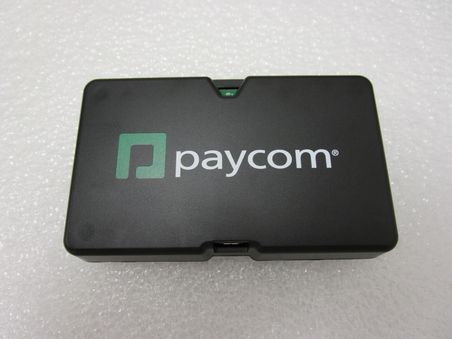
Click to zoom
Application Details
- Equipment Class
- DTS - Digital Transmission System
- Date of Grant
- Dec 01, 2022
- Application Purpose
- Original Equipment
- Date of Application
- Dec 01, 2022
- Equipment Note
- PMF-002NP, PMF-002LP
- Frequency Range
- 2402.00000000 - 2480.00000000
- Company
- Paycom Software, Inc.
- Country
- United States
Documents & Files
Document Text
Text extracted from the exhibit documents filed with the FCC. Open a document above to read the original.
Users Manual
Microfence Installation Manual 1 PMF-002 Microfence Beacon Installation Manual 2 Microfence Installation Manual Thank you for choosing the Paycom Microfence Model PMF- 002. The Microfence uses Bluetooth beacon technology to extend Geofencing Technology into places where GPS signals cannot reach. Table of Contents What's in the box ...................................................................... 3 Components .............................................................................. 3 Choosing Installation Location .................................................. 4 Removing Wall Mount .............................................................. 4 Mounting the Wall Mount ........................................................ 5 Power ........................................................................................ 8 AAA Battery Insertion ............................................................... 9 Power Adapter Usage ............................................................... 9 LED operation............................................................................ 9 Configuring Beacon ................................................................... 9 Employee Phone Requirements ............................................. 13 Troubleshooting ...................................................................... 14 Microfence Installation Manual 3 What's in the box In the box, you will find: • a beacon assigned to your client code • a 5VDC USB power adapter and cable (optional) • Two AAA batteries • An information placard for employees • This installation manual Components The principal components of the Microfence system are shown in the following figures. The front view shows the LED indicator at the top of the beacon and the power jack at the bottom. Figure 1 – Front View LED Power Jack 4 Microfence Installation Manual The bottom view shows the wall mount, which is removable by pressing the release tabs. Figure 2 - Bottom View Choosing Installation Location The Microfence beacon should be placed wherever you want employees to clock in or out. When in operation the unit will transmit a Bluetooth signal periodically that can be received by the Paycom app on employees’ cellphones. The beacon should be mounted on a wall or other surface. Ideally, it should be mounted high on an inside wall in a large, open area, such as a building lobby, breakroom, or similar location where employees may congregate when clocking-in or clocking-out. Since the beacon uses RF technology its range will be improved if the area has few obstructions to block the RF path. Removing Wall Mount The wall mount must be removed to insert batteries or to attached it to a wall with screws. To release the wall mount from the beacon: 1. Press the two release tabs on the bottom as shown in Figure 3. 2. Pivot the wall mount upward as shown. Power Jack Release Tabs Wall Mount Beacon Microfence Installation Manual 5 Figure 3 - Wall Mount Removal Mounting the Wall Mount The figures below show mounting methods for the Paycom beacon. The beacon should be mounted to a flat surface using screws or double-sided tape. LIFT 6 Microfence Installation Manual Figure 4 – Mounting the Wall Mount with Tape When mounting with double-sided mounting tape, removed tape backing on one side and attach to the back face of the unit wall mount. The remove the tape backing on the other side. Carefully position the unit in desired location and press firmly. Microfence Installation Manual 7 Figure 5 - Mounting the Wall Mount with Screws When mounting with screws pilot holes should be drilled prior to inserting screws. The drilling template in the following figure shows proper hole locations. After mounting the wall plate to a wall, remove battery tab and re-attached the beacon to the wall mount. 8 Microfence Installation Manual Figure 6 - Drilling Template (full scale) Power The beacon has 2 power options: 1. a 5V power adapter 2. AAA batteries Either the power adapter or AAA batteries must be installed for the unit to operate. The beacon contains an internal coin cell battery to maintain client-specific configuration information. This coin cell should never be removed. Never remove the coin cell! NOTE: The unit has been pre-programmed to operate on your client code. Removal of the coin cell will cause the unit to lose this programming: If this occurs, please contact Paycom Hardware Support and a Technician can ship you a replacement unit. ! 85 mm (3.3 in) 8 mm dia. ( 0.4 in) 40 mm (1.6 in) 4 mm dia. ( 0.2 in) Microfence Installation Manual 9 AAA Battery Insertion 1. Separate the beacon from the wall mount as shown in prior section. 2. Insert fresh AAA batteries oriented as shown in the battery holder. 3. Snap the beacon back into the wall mount. The wall mount has a retainer to hold the batteries in place. Do not mix old and new batteries! Power Adapter Usage The optional power adapter is attached to the beacon with the provided Micro USB-B cable. 1. Plug the Micro USB-B end of the cable into the beacon USB port. 2. Plug the USB-A end of the cable into the power adapter. 3. Plug the power adapter into the wall. LED operation Upon power-up the beacon LED indicator will blink briefly. Thereafter, the LED indicator will blink briefly every 5 minutes. Configuring Beacon This beacon has been assigned to your client code by Paycom. Before employees can use the beacon, it must be assigned to a web terminal. ! 10 Microfence Installation Manual Log in to Paycom and go to “Time Management → Time and Attendance → Set up Terminal Restrictions”, as shown in Figure 7 below. Figure 7 - Setup Terminal Restrictions Microfence Installation Manual 11 Select the web time clock to be enabled for this beacon, as shown in Figure 8 below. Figure 8 - Web Time Clock Selection Then select the “Microfencing” tab, as shown in Figure 9. Figure 9 – Time Clock Microfencing Tab Add a description for the Microfence beacon, and select the beacon’s MAC Ad…
Text truncated - open the document above for the full version.
Cover Letter(s)
August 22, 2022 Federal Communications Commission Authorization and Evaluation Division 7435 Oakland Mills Road Columbia, Maryland 21046 Dear Sir/Madam: Enclosed please find an application for an original equipment certification of FCC ID: 2A2BS-PMF-002 under Rule Part FCC 15.247. The device is a Bluetooth Low-Energy (BLE) beacon that is used for geolocation of employees when clocking-in/out of or time management system. There are two model variants, a normal-power model and a low-power model. The models are mechanically and electrically identical. Both models have an attenuator between the transmitter and the antenna. The normal power model has a 0 db attenuator whereas the low-power model has a 10 db attenuator. Model numbers are as follows: Model PMF-002NP – normal-power version Model PMF-002LP – low-power version Sincerely, Charles T. Ferguson Sr. Engineer Paycom Software, Inc. [email protected] 800-580-4505 ext 25017
Cover Letter(s)
August 22, 2022 Federal Communications Commission Authorization and Evaluation Division 7435 Oakland Mills Road Columbia, Maryland 21046 Re: Request for confidentiality FCC ID: 2A2BS-PMF-002 To whom it may concern, We hereby respectfully request that under the provision of 47 CFR 0.459 and 0.457(d) the documents listed below and attached with this application for certification be provided with confidential status. • Schematic – SCH_MicroFence-921-1001-30.pdf • Bill-of-Materials – BOM_MicroFence-921-1001-40.xlsx We also hereby request short-term confidential treatment of information accompanying this application as outlined below for a period of 180 days: • Internal Photos Any exhibit / information for which we have requested confidentiality, but which may not be accorded such treatment by the FCC, should be returned to us. The documents listed above contain trade secrets that are treated as confidential by us. Substantial competitive harm to us could result should they be made available to the public. Sincerely, Charles T. Ferguson Sr. Engineer
External Photos
MicrofencePMF-002NP and MicrofencePMF-002LP Photos -External Model PMF-002NP -Front Model PMF-002NP -Back Model PMF-002NP -Bottom Model PMF-002NP -Top Model PMF-002NP -Left Side Model PMF-002NP -Right Side Model PMF-002LP -Front Model PMF-002LP -Back Model PMF-002LP -Bottom Model PMF-002LP -Top Model PMF-002LP -Left Side Model PMF-002LP -Right Side
Internal Photos
MicrofencePMF-002NP and PMF-002LP Photos –Internal PMF-002NP -Component Side PMF-002NP -Back Side PMF-002NP -Bottom PMF-002NP -Right Side PMF-002NP -Top Side PMF-002NP -Left Side PMF-002NP -Back Side (In Housing) PMF-002NP -Bottom (In Housing) PMF-002NP -Right Side (In Housing) PMF-002NP -Top (In Housing) PMF-002NP -Left Side (In Housing) PMF-002LP -Component Side PMF-002LP -Back Side PMF-002LP -Bottom PMF-002LP -Right Side PMF-002LP -Top Side PMF-002LP -Left Side PMF-002LP -Back Side (In Housing) PMF-002LP -Bottom (In Housing) PMF-002LP -Right Side (In Housing) PMF-002LP -Top (In Housing) PMF-002LP -Left Side (In Housing)
Operational Description
1 SWRU120D–April2007–RevisedJanuary2019 SubmitDocumentationFeedback Copyright© 2007–2019,TexasInstrumentsIncorporated 2.4-GHzInvertedF Antenna ApplicationReport SWRU120D–April2007–RevisedJanuary2019 2.4-GHzInvertedF Antenna ABSTRACT Thisdocumentdescribesa printed-circuitboard(PCB)antennadesignthat can be usedwith all 2.4-GHz transceiversand transmittersfromTexasInstruments™. The maximumgainwhenusedon the reference boardis measuredto be +3.3dBi, and the overallsize requirementsfor this antennaare 25.7× 7.5 mm (not includinggroundplane). Contents 1Descriptionof the antennaDesign........................................................................................2 2MeasurementResults.......................................................................................................3 2.1RadiationPattern...................................................................................................3 2.2Reflection...........................................................................................................10 2.3Bandwidth..........................................................................................................11 3Conclusion..................................................................................................................11 4References..................................................................................................................11 Trademarks TexasInstrumentsis a trademarkof TexasInstruments. All othertrademarksare the propertyof theirrespectiveowners. Descriptionof the antennaDesignwww.ti.com 2 SWRU120D–April2007–RevisedJanuary2019 SubmitDocumentationFeedback Copyright© 2007–2019,TexasInstrumentsIncorporated 2.4-GHzInvertedF Antenna 1Descriptionof the antennaDesign It is importantto makean exactcopyof the antennadimensionsto obtainoptimumperformance.The easiestapproachto implementthe antennain a PCBCADtool is to importthe antennalayoutfroma gerberfile or a DXFfile. Suchfiles are includedin CC2430DBreferencedesign[1]. The gerberfile is calledInverted_F_Antenna.spland the DXFfile is calledInverted_F_Antenna.dxf.If the antennais implementedon a PCBthat is widerthanthe antenna,avoidplacingcomponentsor havinga ground planecloseto the end pointsof the antenna.If the CADtool beinguseddoesnot supportimportinggerber or DXFfiles,see Figure1 and Table1. The antennaimpedanceis tunedto 50 ohmon the referenceboard.The impedancewill howeverbe affectedby differentsize and shapeof the groundplane,objectsin the antennanearfieldsuchas mechanicalassemblies(housing,batteries,etc.),PCBthickness,PCBmaterialand so on. It is therefore recommendedto add a pi-networkcloseto the antennafeedpointfor impedancematching. The resultspresentedin this documentare basedon an antennaimplementedon a PCBwith a 1-mm thicknessusingstandardFR-4material. Figure1. IFA Dimensions Table1. IFA Dimensions H15.70mmW20.46mm H20.74mmL125.58mm H31.29mmL216.40mm H42.21mmL32.18mm H50.66mmL44.80mm H61.21mmL51.00mm H70.80mmL61.00mm H81.80mmL73.20mm H90.61mmL80.45mm W11.21mm www.ti.comMeasurementResults 3 SWRU120D–April2007–RevisedJanuary2019 SubmitDocumentationFeedback Copyright© 2007–2019,TexasInstrumentsIncorporated 2.4-GHzInvertedF Antenna 2MeasurementResults All of the resultspresentedin this sectionare basedon measurementsperformedwith the CC2430DB[1] evaluationboard. 2.1RadiationPattern Figure2 showshow to relateall of the radiationpatternsto the orientationof the antenna.The radiation patternsweremeasuredwith the CC2430deviceprogrammedto 0-dBmoutputpower. Figure2. RelatingAntennato RadiationPatterns MeasurementResultswww.ti.com 4 SWRU120D–April2007–RevisedJanuary2019 SubmitDocumentationFeedback Copyright© 2007–2019,TexasInstrumentsIncorporated 2.4-GHzInvertedF Antenna Figure3 showsthe XY planeverticalpolarization. Figure3. XY Plane–VerticalPolarization www.ti.comMeasurementResults 5 SWRU120D–April2007–RevisedJanuary2019 SubmitDocumentationFeedback Copyright© 2007–2019,TexasInstrumentsIncorporated 2.4-GHzInvertedF Antenna Figure4 showsthe XY planehorizontalpolarization. Figure4. XY Plane–HorizontalPolarization MeasurementResultswww.ti.com 6 SWRU120D–April2007–RevisedJanuary2019 SubmitDocumentationFeedback Copyright© 2007–2019,TexasInstrumentsIncorporated 2.4-GHzInvertedF Antenna Figure5 showsthe XZ planeverticalpolarization. Figure5. XZ Plane–VerticalPolarization www.ti.comMeasurementResults 7 SWRU120D–April2007–RevisedJanuary2019 SubmitDocumentationFeedback Copyright© 2007–2019,TexasInstrumentsIncorporated 2.4-GHzInvertedF Antenna Figure6 showsthe XZ planehorizontalpolarization. Figure6. XZ Plane–HorizontalPolarization MeasurementResultswww.ti.com 8 SWRU120D–April2007–RevisedJanuary2019 SubmitDocumentationFeedback Copyright© 2007–2019,TexasInstrumentsIncorporated 2.4-GHzInvertedF Antenna Figure7 showsthe YZ planeverticalpolarization. Figure7. YZ Plane–VerticalPolarization www.ti.comMeasurementResults 9 SWRU120D–April2007–RevisedJanuary2019 SubmitDocumentationFeedback Copyright© 2007–2019,TexasInstrumentsIncorporated 2.4-GHzInvertedF Antenna Figure8 showsthe YZ planehorizontalpolarization. Figure8. YZ Plane–HorizontalPolarization MeasurementResultswww.ti.com 10 SWRU120D–April2007–RevisedJanuary2019 SubmitDocumentationFeedback Copyright© 2007–2019,TexasInstrumentsIncorporated 2.4-GHzInvertedF Antenna 2.2Reflection Figure9 showsthat the IFA ensuresless than10%reflectionof the availablepowerfor a bandwidthof morethan300 MHz.A largebandwidthmakesthe antennaless sensitiveto detuningbecauseof plastic encapsulationor otherobjectsin the vicinityof the antenna. Figure9. MeasuredReflectionat FeedPointof Antenna www.ti.comMeasurementResults 11 SWRU120D–April2007–RevisedJanuary2019 SubmitDocumentationFeedback Copyright© 2007–2019,TexasInstrumentsIncorporated 2.4-GHzInvertedF Antenna 2.3Bandwidth Anotherway of measuringthe bandwidthafterthe antennais implementedon a PCBand connectedto a transmitteris to writetest softwarethat stepsa carrieracrossthe frequencybandof interest.By usingthe …
Text truncated - open the document above for the full version.
Operational Description
1 Vicki Albertson From:[email protected] Sent: Friday, August 12, 2022 6:03 AM To: Vicki Albertson Subject: Response to Inquiry to FCC (Tracking Number 972967) (TCB) Importance: High CAUTION:This email originated from outside of Element Materials Technology. DO NOT click links or open attachments unless you recognize the sender and know the content is safe. Please contact IT Service Desk if you are in any doubt about this email. Inquiry on 08/09/2022 : Inquiry: The FCC rules are specific about the definition of identical. 2.924 states that marketing devices with different model or type numbers can be done if the devices are electrically identical. 2.932 states that, except for approved permissive changes a new FCC ID is required for any changes in the circuitry of the device where authorization has been issued. An applicant has a Part 15 transmitter where the only change done to the transmitter circuitry is to insert a 10 dB attenuator or a zero-ohm resistor (0dB attenuator) between the antenna matching circuitry and the antenna. This result is two models of the same otherwise identical device, one at a 10 dB lower power than the other. The question relates to the insertion of the attenuator. The applicant would like the device under one FCC ID number but have two variants (models). One high power, one 10 dB lower power. Is it acceptable to have both models under the same FCC ID or, because of the different values of attenuator, would this require 2 separate FCC ID? FCC response on 08/12/2022 Only one FCC identifier is required. Attachment Details: 2 Do not reply to this message. Please select the Reply to an Inquiry Response link from the OET Inquiry System to add any additional information pertaining to this inquiry.
Operational Description
1 Vicki Albertson From:Certification Bureau / Bureau homologation (IC) <certificationbureau-bureauhomologation@ised- isde.gc.ca> Sent: Thursday, August 11, 2022 11:20 AM To: Vicki Albertson Subject: RE: Question about "electrically identical" and the need for one IC ID vs two Good Day Vicki, ISED will allow this time due to low risk but this case should not translated into general acceptance of changes such as these for other products. Regards, Engineering, Planning and Standards Branch (14) Innovation, Science and Economic Development Canada / Government of Canada Tel: 613-990-4218 / TTY: 1-866-694-8389 Direction générale du génie, de la planification et des normes (14) Innovation, Sciences et Développement économique Canada / Gouvernement du Canada Tél: 613-990-4218 / ATS: 1-866-694-8389 [email protected] From: Vicki Albertson <[email protected]> Sent: Wednesday, August 10, 2022 2:01 PM To: Certification Bureau / Bureau homologation (IC) <[email protected]> Subject: RE: Question about "electrically identical" and the need for one IC ID vs two Hi, Please see comments in RED Let me know if you need more information. Thanks Vicki Albertson 2 Certification Manager Element Materials Technology 6775 NE Evergreen Parkway, Suite 400 Hillsboro , OR 97124 , United States O +1 503 844 4066 ext. 10168 [email protected] www.element.com From: Certification Bureau / Bureau homologation (IC) <[email protected]> Sent: Wednesday, August 10, 2022 7:46 AM To: Vicki Albertson <[email protected]> Subject: RE: Question about "electrically identical" and the need for one IC ID vs two CAUTION:This email originated from outside of Element Materials Technology. DO NOT click links or open attachments unless you recognize the sender and know the content is safe. Please contact IT Service Desk if you are in any doubt about this email. Good Day Vicki, 1. ISED allows different antennas and/or switching circuitry to the antenna for HVINs within a family certification. 2. ISED is not concerned with different power levels for each HVIN within a family as this is permitted. 3. ISED does not allow changes to RF circuitry between HVINs within a family certification. This change could fall under either of these conditions depending on how and where the change is occurring. ISED requires further information to decide and needs the two board layouts with components to compare. Please see attached excerpt from Schematics – it has an arrow pointing to the component that is changing, and there is a table below to indicate the values for the two model variants. Also attached is the datasheet for the attenuator. ISED needs to know if the attenuation is achieved with passive components only? Yes, it is passive Has the product been fully retested? Both variants will be fully tested Regards, Engineering, Planning and Standards Branch (14) Innovation, Science and Economic Development Canada / Government of Canada Tel: 613-990-4218 / TTY: 1-866-694-8389 Direction générale du génie, de la planification et des normes (14) Innovation, Sciences et Développement économique Canada / Gouvernement du Canada Tél: 613-990-4218 / ATS: 1-866-694-8389 [email protected] From: Vicki Albertson <[email protected]> Sent: Tuesday, August 9, 2022 4:52 PM To: [email protected] Subject: Question about "electrically identical" and the need for one IC ID vs two 3 Hi, ISED is pretty specific about devices being electrically identical. RSP 100 section 9.3 allows family certification for minor PCB modifications that improve existing frequency band/technologies and/or add non-RF features. It further states that all product versions within the family must be identical or have differences permitted under the permissive change requirements. An applicant has an unlicensed transmitter where the only change done to the transmitter circuitry is to insert a 10 dB attenuator or a zero ohm resistor (0dB attenuator) between the antenna matching circuitry and the antenna. No other differences exist in the device. The result is two models of the same otherwise identical device, one at a 10 dB lower power than the other. The question relates to the insertion of the attenuator and how to file for certification. Because of the 10 dB difference in power due to either a 10dB or 0dB (0 ohm resistor) being inserted, could this be two different model numbers under one family certification, or, because the difference in value of the inserted dB pad resulting in 10dB difference in power levels, would this require two different ISED numbers? Please advise. Thanks, Vicki Vicki Albertson Certification Manager Element Materials Technology 6775 NE Evergreen Parkway, Suite 400 Hillsboro , OR 97124 , United States O +1 503 844 4066 ext. 10168 [email protected] www.element.com Disclaimer This email is sent on behalf of Element Materials Technology Group Limited or the relevant group company with which you are dealing (together, Element). Element Materials Technology Group Limited is a limited company registered in England and Wales with registered number 09915743. Its registered office is at 5 Fleet Place, London, England, United Kingdom, EC4M 7RD and its principal place of business is at 3rd Floor, Davidson Building, 5 Southampton Street, London, United Kingdom, WC2E 7HA. 4 Element cannot accept responsibility for any loss or damage sustained as a result of viruses or malware and the recipient must ensure that the email and attachments are virus and malware free. Emails and attachments are opened at your own risk. The information transferred is intended only for the person or entity to which it is addressed and may contain confidential and/or privileged material. Transmission of this email is not intended to waive confidentiality and/or privilege. Th…
Text truncated - open the document above for the full version.
Operational Description
November 27, 2022 Rev 10 Page 1 of 4 Operational Description Microfence BLE Beacon FCC ID: 2A2BS-PMF-002 IC ID: 29128-PMF002 Model: PMF-002NP (normal power) Model: PMF002LP (low power) Chuck Ferguson November 27, 2022 Revision 10 Operational Description Microfence BLE Beacon November 27, 2022 Rev 10 Page 2 of 4 1 Operational Description The PMF-002NP and PMF-002LP Microfence BLE Beacons is a family of Bluetooth Low-Energy (BLE) beacons used for geolocation of employees when clocking-in/out of or time management system. The beacons advertise a rolling code every 500 ms that is received by employee’s cell phone. The rolling code is used to authenticate time clock punches. The beacons use the Texas Instruments’ ultra-low power, multi-protocol, wireless MCU, CC2640R2F. The beacons contains a single internal PCB containing all required passive components, including a 32.768 kHz crystal, a 24 MHz crystal and an on-board 2.4-GHz Inverted F patch antenna integral to the PCB. The CC2640R2F within the beacon contains an integrated ARM processor that uses TI’s Bluetooth® low energy stack running GFSK modulation at 1 Mbps data rate. The actual frequency range of the beacon is 2.402 to 2.480 Ghz. The CC2640R2F radio includes a 4.8 GHz PLL running off the 24 MHz crystal oscillator. The PLL outputs the 2.4 GHz digitally modulated RF signal which is amplified in the IC- internal PA and then output on the ICs differential RF pins. The PA can be controlled from -21 dBm to 5 dBm output power. On the beacon PCB the differential RF output is transformed to a single ended 50 ohm signal through a passive component (capacitor / inductor) balun. The output of the balun is passed through a T-filter to reduce harmonic emission and then connected to the PCB patch antenna. These components are not individually hand-selected and their values are subject to variation due to manufacturing tolerances. Engineering analysis has determined that the best case (highest power to antenna) is 2.925 db path loss. When the transmitter PA is set to 5 dBm (maximum) the input to the antenna will be 2.075 dBm in this optimal case. Actual performance will typically be less than optimal and can be significantly lower, depending on actual values of components. The antenna has 3.3 dBi gain so EIRP can never exceed 5.375 dBm. This EIRP is more than 30 db below regulatory limit of 36 dBm per FCC 15.247:2022 and RSS-247 Issue 2:2017. The 2.4-GHz Inverted F patch antenna on the module is an exact copy of Texas Instruments reference design 1 . All antenna dimensions are identical to the reference design. The antenna is integral to the PCB and as such not replaceable by the end user. The beacon is manufactured in two variants: a normal-power variant and a low-power variant. The low power variant has a shorter range than the normal power variant. An impedance-matched attenuator between the transmitter and the inverted F patch antenna is the sole difference. The low-power variant has 10 db attenuator in the RF 1 Texas Instruments Application Report SWRU120D, “2.4-GHz Inverted F Antenna”, April 2007, Revised January 2019. Operational Description Microfence BLE Beacon November 27, 2022 Rev 10 Page 3 of 4 path, which correspondingly reduces transmit power and range. The normal-power variant is populated with a 0 db attenuator in the RF path. The beacon PA (on the TI CC2640 chip) transmits at 0 dBm power by default. Beacon testing was conducted at 5 dBm (maximum) power and -21 dBm (minimum) power. The attenuator used to differentiate the normal and low power product variants is comprised of a network of resistive lumped elements operating only inside their linear frequency ranges with respect to their third order parasitic effects on the PCB. In light of this, the EMC wireless performance should remain linear between PMF-002NP and PMF-002LP’s through their highest and lowest software settings minus the 10dB hardware attenuation. Thus, testing the highest power level setting of both variants while testing the lowest power setting on just one variant should prove out compliance. Beacon PA power is controlled by processor firmware and is selectable only by the manufacturer. Transmit power is typically set to 0 dBm but may be as low as -21 dBm to reduce transmission range. No radio settings are controllable by the end user. The unit was tested with firmware version 2021.06.27, which has frequency hopping disabled (CW) and maximum transmit power. The production firmware version is 2022.08.04. The manufacturing tolerance in transmit output power (in dB) is determined by the Texas Instruments CC2640R2F chip set. Please refer to the data sheet for the part. The duty cycle of the radio transmitter is fixed at 0.0496%. The duty cycle is brief as is typical of all Bluetooth Low-Energy devices. An advertisement message is transmitted every 500 ms. The advertisement is 31 bytes (248 bits) long, resulting in a on-time of 248 μs for the transmitter every 500 ms. Operational Description Microfence BLE Beacon November 27, 2022 Rev 10 Page 4 of 4 2 Revision History Rev. Date Originator Description 0 August 22, 2022 Chuck Ferguson Initial release 1 September 2, 2022 Chuck Ferguson Revised “clone” of antenna to “exact copy” per Element request. 2 September 27, 2002 Chuck Ferguson Added IC ID to cover page. Added separate model numbers for normal power and low power. Corrected ’10 ohm’ with ’10 db’. Added description of use. 3 September 29, 2022 Chuck Ferguson Firmware disables changing transmitter settings, such as power & frequency. 4 October 24, 2022 Chuck Ferguson Added footnote for antenna spec. Added note about firmware versions. 5 November 4, 2022 Chuck Ferguson Revised transmitter power during test to 3 dbm. 6 November 11, 2022 Chuck Ferguson Transmit power selectable by users. 7 November 11, 2022 Chuck Ferguson Explicitly stated that users have no control of any radio parameters other than transmit power. 8 November 16, 2022 Chuck Ferguson Revised per actions f…
Text truncated - open the document above for the full version.
RF Exposure Info
This report must not be used to claim product certification, approval, or endorsement by A2LA or any agency of the U.S. Government. This Report shall not be reproduced, except in full without written approval of the laboratory. EAR-Controlled Data - This document contains technical data whose export and reexport/retransfer is subject to control by the U.S. Department of Commerce under the Export Administration Act and the Export Administration Regulations. The Department of Commerce’s prior written approval may be required for the export or re- export/retransfer of such technical data to any foreign person, foreign entity or foreign organization whether in the United States or abroad. Paycom Software, Inc. PMF-002NP Microfence Bluetooth Low Energy Beacon FCC 1.1307:2022 Bluetooth Low Energy Report: PAYC0009.2 Rev. 1, Issue Date: November 29, 2022 CERTIFICATE OF EVALUATION 2018-09-14 Product compliance is the responsibility of the client; therefore, the tests and equipment modes of operation represented in this report were agreed upon by the client, prior to testing. The results of this test pertain only to the sample(s) tested. The specific description is noted in each of the individual sections of the test report supporting this certificate …
Text truncated - open the document above for the full version.
Contact Information
Applicant
Charles T Ferguson(Engineer)
Test Firm
Element Materials Technology Dallas - PlanoRenee Walker
[email protected]503 844 4066
Technical Specifications
| # | Rule Parts | Frequency Range | Power Output |
|---|---|---|---|
| 1 | 15C | 2.40 GHz - 2.48 GHz | 2.00 mW |