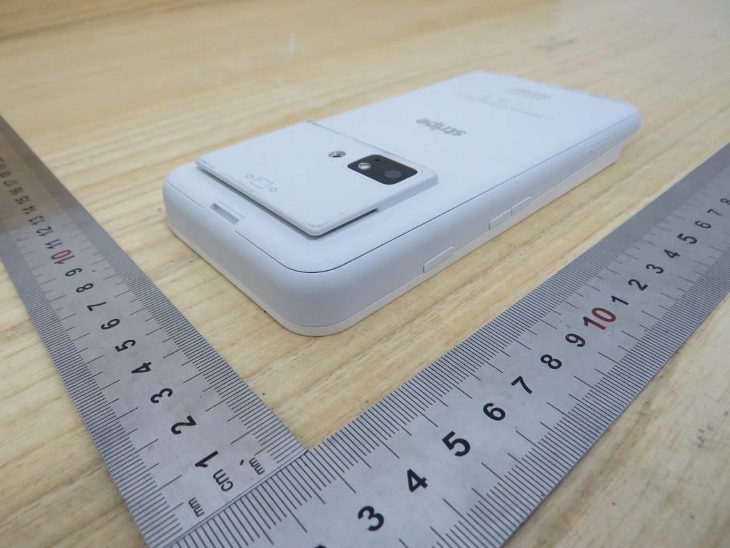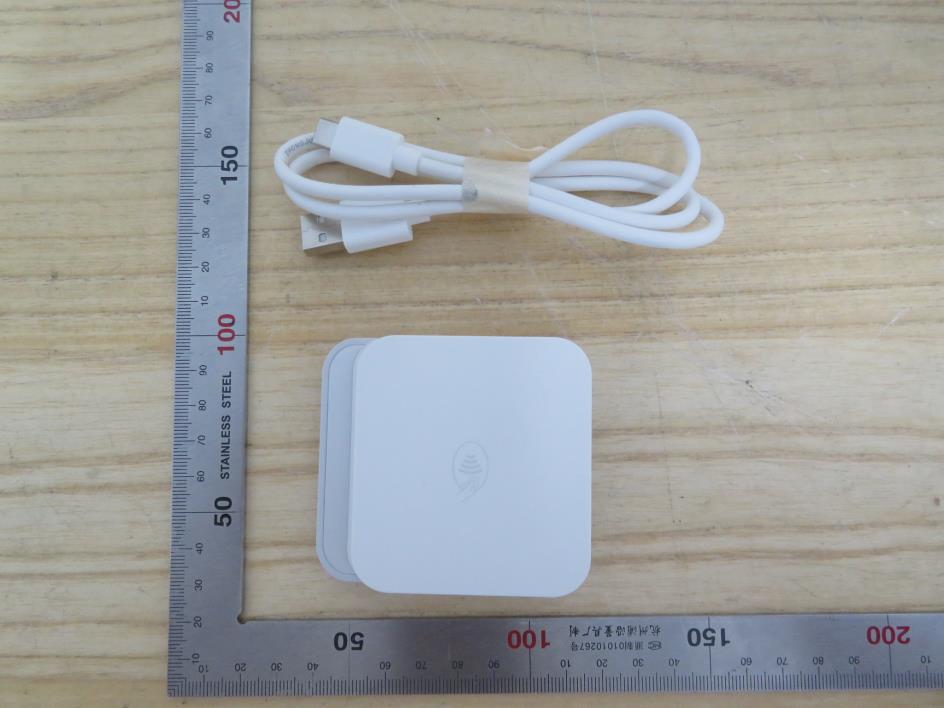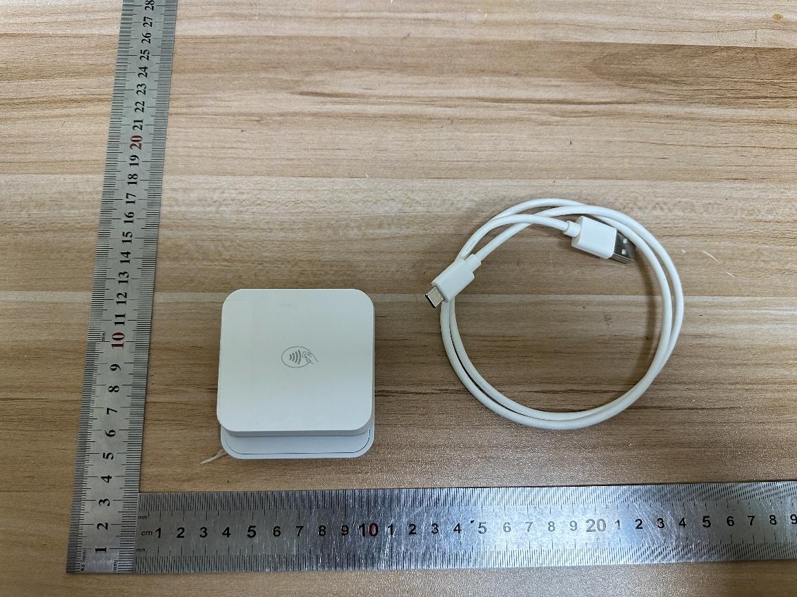
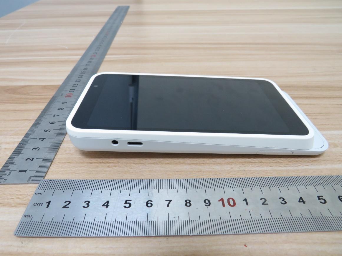
FCCID.CO- FCC ID Database
HomeCompaniesEquipment ClassesSearch

© 2026 FCC ID Database. All rights reserved.

AboutContactData sourced from FCC public records
  1. Home/
  2. Stripe, Inc./
  3. 2A2ES-STRM2V2

2A2ES-STRM2V2Stripe Reader M2

Stripe, Inc.
Stripe Reader M2 - FCC ID 2A2ES-STRM2V2 - Stripe, Inc.
Click to zoom

Application Details

Equipment Class
DXX - Part 15 Low Power Communication Device Transmitter
Date of Grant
Aug 06, 2026
Application Purpose
Original Equipment
Equipment Note
Stripe Reader M2
Frequency Range
13.56000000 - 13.56000000
Company
Stripe, Inc.
Country
United States

Documents & Files

Select a file to view
Users Manual

↗

Attestation Statements

↗
↗

Cover Letter(s)

↗
↗
↗

External Photos

↗

ID Label/Location Info

↗

Internal Photos

↗

RF Exposure Info

↗
↗
↗
↗
↗

Test Report

↗
↗

Test Setup Photos

↗
↗

Document Text

Text extracted from the exhibit documents filed with the FCC. Open a document above to read the original.

Users Manual

Mobile reader for chip, contactless and swipe Stripe Reader M2 www.stripe.c om/terminal Supported SDKs: iOS and android Ready for payment LED 1 ON Reading card information LEDs ON in consecutive order Car d read successful 4 LEDs ON + “BEEP” Transaction completed “BEEP” Standby mode LED 1 ashing Remove card (after successful payment) or error , please retry 2 “BEEP”s Set Up Instructions Device X1 USB-A to USB-C cable X1 STEP 1 Connect the charging cable to the reader and charge it for two hours before initial use. Please use the charging cable provided in the reader box. ** For contactless tap, please ensure the card or mobile device is placed within 4cm of the contactless tap logo. For magswipe and card insert payments , please ensure the card is orienta ted correctly as shown. STEP 2 Step 2: Power on the reader and enable Bluetooth on your phone or tablet. Connect the reader to your phone or tablet using your point of sale app, not device settings. Reset button USB-C charging port Reader Overview Power button EMV card insert slot Magstripe slot NFC contactless tap location LED status indicators Package Contents LED Sta tus Indicators Charging Sta tus Full charge 75% charge 25% charge 50% charge Charging Bluetooth connected 4 LEDs ash 3 times USB connected Device tampered LED 1 & 4 ashingLED 1 & 4 ON Device integrity check failed 4 LEDs ash 3 times Waiting for Bluetooth pairing LEDs ON & OFF in consecutive order • Device has no response • A tampered device will trigger the self-protection mechanism by removing security keys data from the device and the device will stop operating. • The rst and fourth LED on the front side will be ashing rapidly. • Contact your service provider for more information. Device tampered • Device self-check failure • The rst and fourth LED on the front side turn on. • Use a paper clip to press the reset button at the bottom for reboot. • Contact your service provider for more information if it does not work after the reset button pressed. Device integrity check failed FCC Caution Sta tements: FCC Supplier’s Declaration of Conformity: FCC ID: 2A2ES-STRM2V2 This device complies with Par t 15 of the FCC Rules. Operation is subject to the following two conditions: (1) This device may not cause harmful in terfer ence, and (2) This device must accept any in terfer ence received, including interfer ence that may cause undesired operation. Stripe, Inc., 354 Oyster Point Blvd, South San Francisco, CA 94080, USA Inter net contact: [email protected] om Caution: Any changes or modi cations not expressly approved by the party responsible for compliance could void the user's authorit y to operate the equipment. This equipment has been tested and found to comply with the limits for a Class B digital device, pursuant to part 15 of the FCC rules. These limits ar e designed to provide reasonable protection against harmful in terfer ence in a residential installation. This equipment generates, uses and can radiate radio fr equency energy and, if not installed and used in accordance with the instructions, may cause harmful in terfer ence to radio communications. However , there is no guarantee that in terfer ence will not occur in a particular installation. If this equipment does cause harmful in terfer ence to radio or television rec eption, which can be deter mined by turning the equipment o and on, the user is encouraged to tr y to correct the in terfer ence by one or more of the following measures: - Reorient or relocate the receiving antenna. - I ncrease the separation between the equipment and receiver . - Connect the equipment in to an outlet on a circuit di er ent fr om that to which the receiver is connected. - Consult the dealer or an experienced radio/TV technician for help. This tr ansmitter must not be co-located or operating in conjunction with any other antenna or tr ansmitter . This device complies with FCC RF exposure limits. The maximum reported SAR value is 0.03 W/kg (extremity), which is below the FCC limit of 4.0 W/kg. War ranty • Any damage or defects caused by a failure to follow the instruction which relate to this device or as the result of an accident, abuse, misuse, misapplication, product modication, improper voltage or current, acts of God, shipping damages or loss, or damage caused by service performed by anyone other than our company are expressly excluded from the warranty stated below. • Please contact the dealer for any war ranty or customer support services. Any repair of the device by yourself will void the War ranty. ©2021 Stripe, Inc., All rights reserved. iOS is the tr ademark of Apple Inc. Android™ is a tr ademark of Google Inc. The Bluetooth® word mark and logos ar e register ed tr ademarks owned by Bluetooth SIG, Inc. and any use of such marks by Str ipe, Inc., is under license. Other tr ademarks and tr ade names ar e those of their respective owners. All details ar e subject to change without prior notice. Stripe, Inc., 354 Oyster Point Blvd, South San Francisco, CA 94080, USA Inter net contact: [email protected] om Cautions & Important Notes • Ensure the device is fully charged before use. • Please ensure magstripe/ EMV chip of the card is facing the right direction when swiping or inserting card. • The NFC card should be tapped within 4 cm range on top of the reader mark. • Don’t drop, disassemble, t ear, open, crush, bend, deform, puncture, shred, microwave, incinerate, paint or insert f oreign object into the device. Doing any of which will damage the device and void the War ranty. • Don’t immerse the device into water and place near washbasins or any wet locations. Don’t spill food or liquid on the devices. Don’t att empt to dry the device with exter nal heat sources, such as microwave or hair dryer . Don’t use any corrosive solvent or water to clean the device. Recommend using dry cloth to clean the surface only. • Don’t use any sharp tools to point the inter nal components , connectors or contacts , doing which may lead to device …

Text truncated - open the document above for the full version.

RF Exposure Info

Report No.: TSEA26060058601 Appendix B NFC Scans Setup Area ScanZoom Scan Grid Extents [mm]140.0 x 140.032.0 x 32.0 x 30.0 Grid Steps [mm]15.0 x 15.08.0 x 8.0 x 5.0 Sensor Surface [mm]3.01.4 Graded GridN/AYes Grading RatioN/A1.5 MAIAN/AN/A Surface DetectionVMS + 6pVMS + 6p Scan MethodMeasuredMeasured Measurement Results Area ScanZoom Scan Date2026-07-03, 14:332026-07-03, 14:37 psSAR1g [W/Kg]0.1260.087 psSAR10g [W/Kg]0.0610.034 Power Drift [dB]0.040.05 Power ScalingDisabledDisabled Scaling Factor [dB] TSL CorrectionNo correctionNo correction M2/M1 [%]32.2 Dist 3dB Peak [mm]9.2 Test Laboratory: TOWE Lab Measurement Report for STRM2, FRONT, Custom Band, CW, Channel 13600 (13.600 MHz) Device Under Test Properties ModelDimensions [mm] STRM273.0 x 66.0 x 20.0 Exposure Conditions Phantom Section, TSLPosition, Test Distance [mm] BandGroup, UID Frequency [MHz], Channel Number Conversion Factor TSL Conductivity [S/m] TSL Permittivity Flat, Head Simulating Liquid FRONT, 0.00Custom Band CW, 0--13.600, 1360018.680.78556.0 Hardware Setup PhantomTSLProbe, Calibration DateDAE, Calibration Date ELI V8.0 (20deg probe tilt) - 2222HSL13MHzEX3DV4 - SN7858, 2026-02-20DAE4ip Sn1846, 2026-01-07

Test Setup Photos

Appendix II Setup Photographs RADIATED RF MEASUREMENT SETUP (ABOVE 1 GHz) MEASUREMENT POSITION MEASUREMENT POSITION (X axis) MEASUREMENT POSITION (Y axis) MEASUREMENT POSITION (Z axis) RADIATED RF MEASUREMENT SETUP (30MHz~1GHz) RADIATED RF MEASUREMENT SETUP (Below 30MHz) AC CONDUCTED POWER LINE SETUP

Test Setup Photos

Report No.: TSEA26060058601 Appendix D 1. Test Sample Photo 1: Front View Photo 2: Back View 2. Antenna position map Photo 3: Antenna position Right Left Bottom Top Report No.: TSEA26060058601 3. Test positions for SAR Photo 4: Front Side 0mm Photo 5: Back Side 0mm Photo 6: Left Side 0mm Photo 7: Right Side 0mm Photo 8: Top Side 0mm Photo 9: Bottom Side 0mm

Test Report

Frequency (MHz) Antenna Type Antenna Gain (dBi) 13.56 Pattern antenna 0 Antenna size: 53mm*48mm All measurements were performed radiated and therefore additional antenna gain documentation is not required.

Test Report

The results reported herein have been performed in accordance with the laboratory’s terms of accreditation. This report shall not be reproduced except in full without the written approval of the Laboratory. The results in this report apply to the test sample(s) mentioned above at the time of the testing period only and are not to be used to indicate applicability to other similar products. This report does not imply that the product(s) has met the criteria for certification. FCC 47 CFR PART 15 SUBPART C CERTIFICATION TEST REPORT For Stripe Reader M2 MODEL NUMBER: STRM2, CHB3B REPORT NUMBER: 4792069165-1-RF-3 ISSUE DATE: June 16, 2026 FCC ID:2A2ES-STRM2V2 Prepared for Stripe, Inc. 354 Oyster Point Blvd, South San Francisco, CA 94080, USA Prepared by UL Verification Services (Guangzhou) Co., Ltd, Song Shan Lake Branch Room 101, Building 2, No.4, Information Road, Songshan Lake, Dongguan, Guangdong, China Tel: +86 769 22038881 Fax: +86 769 33244054 Website: www.ul.com REPORT NO.: 4792069165-1-RF-3 Page 2 of 32 UL Verification Services (Guangzhou) Co., Ltd, Song Shan Lake Branch FORM NO: 10-SL-F0059 This report shall not be reproduced except in full, without the written approval of UL Verification Services (Guangzhou) Co., Ltd, Song Shan Lake Branch. . Revision History Rev. Issue Date Revisions Revised By V0 June 16, 2026 Initial Issue REPORT NO.: 4792069165-1-RF-3 Page 3 of 32 UL Verification Services (Guangzhou) Co., Ltd, Song Shan Lake Branch FORM NO: 10-SL-F0059 This report shall not be reproduced except in full, without the written approval of UL Verification Services (Guangzhou) Co., Ltd, Song Shan Lake Branch. . Summary of Test Results Clause Test Items FCC Rules Test Results 1 Transmitter 99% Emission Bandwidth / 20dB Bandwidth Part 15.215 (c) PASS 2 Transmitter Frequency Stability (Temperature & Voltage Variation) FCC 47 CFR §15.225(e) PASS 3 Fundamental Field Strength FCC 47 CFR §15.225(a)(b)(c)(d) PASS 4 Radiated Emissions FCC 47 CFR§15.209(a) FCC 47 CFR§15.225(d) PASS 5 Band Edge Radiated Emissions FCC 47 CFR §15.209(a) FCC 47 CFR §15.225(c)(d) PASS 6 AC Power Line Conducted Emission FCC Part 15.207 PASS 7 Antenna Requirement FCC 47 CFR §15.203 PASS Note 1: This test report is only published to and used by the applicant, and it is not for evidence purpose in China. Note 2: The measurement result for the sample received is <Pass> according to < FCC 47 CFR PART 15 SUBPART C> when <Simple Acceptance> decision rule is applied. REPORT NO.: 4792069165-1-RF-3 Page 4 of 32 UL Verification Services (Guangzhou) Co., Ltd, Song Shan Lake Branch FORM NO: 10-SL-F0059 This report shall not be reproduced except in full, without the written approval of UL Verification Services (Guangzhou) Co., Ltd, Song Shan Lake Branch. . TABLE OF CONTENTS 1. ATTESTATION OF TEST RESULTS .................................................................................... 5 2. TEST METHODOLOGY ........................................................................................................ 6 3. FACILITIES AND ACCREDITATION .................................................................................... 6 4. CALIBRATION AND UNCERTAINTY .................................................................................. 7 4.1. MEASURING INSTRUMENT CALIBRATION ................................................................ 7 4.2. MEASUREMENT UNCERTAINTY ................................................................................. 7 5. EQUIPMENT UNDER TEST ................................................................................................. 8 5.1. DESCRIPTION OF EUT ................................................................................................. 8 5.2. MAXIMUM FIELD STRENGTH ...................................................................................... 8 5.3. DESCRIPTION OF AVAILABLE ANTENNAS ................................................................ 8 5.4. TEST ENVIRONMENT ................................................................................................... 9 5.5. SUPPORT UNITS FOR SYSTEM TEST ...................................................................... 10 5.6. MEASURING INSTRUMENT AND SOFTWARE USED .............................................. 11 6. ANTENNA PORT TEST RESULTS .................................................................................... 12 6.1. 99% & 20dB BANDWIDTH ........................................................................................... 12 6.2. TRANSMITTER FREQUENCY STABILITY ................................................................. 14 7. RADIATED EMISSION TEST RESULTS ............................................................................ 17 7.1. FIELD STRENGTH OF INTENTIONAL EMISSIONS ................................................... 22 7.2. SPURIOUS EMISSIONS BELOW 1GHz AND ABOVE 30MHz ................................... 23 7.3. SPURIOUS EMISSIONS BELOW 30MHz ................................................................... 25 8. AC POWER LINE CONDUCTED EMISSIONS ................................................................... 28 9. ANTENNA REQUIREMENTS ............................................................................................. 32 REPORT NO.: 4792069165-1-RF-3 Page 5 of 32 UL Verification Services (Guangzhou) Co., Ltd, Song Shan Lake Branch FORM NO: 10-SL-F0059 This report shall not be reproduced except in full, without the written approval of UL Verification Services (Guangzhou) Co., Ltd, Song Shan Lake Branch. . 1. ATTESTATION OF TEST RESULTS Applicant Information Company Name: Stripe, Inc. Address: 354 Oyster Point Blvd, South San Francisco, CA 94080, USA Manufacturer Information Company Name: Stripe, Inc. Address: 354 Oyster Point Blvd, South San Francisco, CA 94080, USA EUT Information EUT Name: Stripe Reader M2 Model: STRM2 Series Model Number: CHB3B Model Difference: They are all the same except the model name. Brand: Stripe Sample Received Date: F…

Text truncated - open the document above for the full version.

RF Exposure Info

Sushi TOWE Wireless Testing (Shenzhen) Co., Ltd. Report No.: TSEA26060058601 Sushi TOWE Wireless Testing(Shenzhen) Co., Ltd. Email: [email protected] Tel.: +86-755-27212361 TOWE-QP-15-F05 Rev.1.1 All rights reserved. Unless otherwise specified, no part of this report may be reproduced or utilized in any part, form or by any means, electronic or mechanical, including photocopying and microfilm, without permission in writing from TOWE. FCC SAR Test Report Applicant: Stripe, Inc. EUT Description: Stripe Reader M2 Model: STRM2, CHB3B Test Model: STRM2 Brand: Stripe FCC ID: 2A2ES-STRM2V2 Standards: FCC 47CFR §2.1093 Date of Receipt: 2026/06/12 Date of Test: 2026/07/03 Date of Issue: 2026/07/08 TOWE. tested the above equipment in accordance with the requirements set forth in the above standards. The test results show that the equipment tested is capable of demonstrating compliance with the requirements as documented in this report. the results documented in this report apply only the tested sample, under the conditions and modes of operation as described herein. It is the manufacturer's responsibility assure that additional production units of the model are manufactured with identical electrical and mechanical components. All sample tested were in good operating condition throughout the entire test program. Measurement Uncertainties are published for informational purposes only and were not taken into account unless noted otherwise. without written approval of TOWE, the test report shall not be reproduced except in full. Jim Huang Approved By: Jack Li Reviewed By: Page 2 / 18 Report No.: TSEA26060058601 Sushi TOWE Wireless Testing(Shenzhen) Co., Ltd. Email: [email protected] Tel.: +86-755-27212361 TOWE-QP-15-F05 Rev.1.1 All rights reserved. Unless otherwise specified, no part of this report may be reproduced or utilized in any part, form or by any means, electronic or mechanical, including photocopying and microfilm, without permission in writing from TOWE. Revision History Rev. Issue Date Description Revised by 01 2026/07/08 Original Jack Li Page 3 / 18 Report No.: TSEA26060058601 Sushi TOWE Wireless Testing(Shenzhen) Co., Ltd. Email: [email protected] Tel.: +86-755-27212361 TOWE-QP-15-F05 Rev.1.1 All rights reserved. Unless otherwise specified, no part of this report may be reproduced or utilized in any part, form or by any means, electronic or mechanical, including photocopying and microfilm, without permission in writing from TOWE. Table of Contents 1 Summary of Test Results .............................................................................................................................. 4 2 Guidance Applied ........................................................................................................................................... 5 3 Lab Information ............................................................................................................................................... 5 3.1 Testing Location ...................................................................................................................................................................... 5 3.2 Test Facility / Accreditations ................................................................................................................................................ 5 3.3 Ambient Condition .................................................................................................................................................................. 5 4 Client Information ........................................................................................................................................... 5 4.1 Applicant ................................................................................................................................................................................... 5 4.2 Manufacturer ............................................................................................................................................................................ 5 5 Product Information ....................................................................................................................................... 6 5.1 Antenna Locations .................................................................................................................................................................. 6 6 RF Exposure Limits ........................................................................................................................................ 7 7 Introduction ..................................................................................................................................................... 8 7.1 SAR Definition .......................................................................................................................................................................... 8 8 SAR Measurements System .......................................................................................................................... 9 8.1 The SAR Measurement Set-up ............................................................................................................................................. 9 8.2 Measurement procedure ..................................................................................................................................................... 10 8.2.1 Power reference measurement ................................................................................................................................... 10 8.2.2 Area scan ....................................................................................................................................................................... 10 8.2.3 Zoom Scan ...................................................................................................................................................................…

Text truncated - open the document above for the full version.

RF Exposure Info

CLA13 SN 1043 Extended Dipole Calibrations Referring to KDB 865664, if dipoles are verified in return loss (<-20dB, within 20% of prior calibration), and in impedance (within 5 ohm of prior calibration), the annual calibration is not necessary, and the calibration interval can be extended. Dipole CLA13 (SN 1043) 750MHz Head Liquid Date of Measurement Return Loss(dB) Δ % Real Impedance (Ω) ΔΩ Imaginary Impedance (Ω) ΔΩ 2024-01-03 (Cal. Report) -22.8 / 54.2 / -6.2 / 2025-01-02 (extended) -22.797 -0.01 53.286 -0.914 -6.8563 -0.6563 2026-01-02 (extended) -22.814 0.06 53.835 -0.365 -6.472 -0.272 The return loss is < -20dB, within 20% of prior calibration; the impedance is within 5 ohm of prior calibration. Therefore the verification result should support extended calibration. Dipole Verification Data: 2025-01-02 Dipole Verification Data: 2026-01-02

RF Exposure Info

Report No.: TSEA26060058601 Appendix C EX3DV4 - SN 7858 DAE4 - SN 1846 CLA13 – SN1043

Attestation Statements

Stripe, Inc. Date: 7/15/2026 Federal Communications Commissions Authorization and Evaluation Division 7435 Oakland Mills Road Columbia, MD 21046 RE: CFR 47 §2.911 (d)(7) Agent Designation Attestation Grantee Code: 2A2ES FRN: 0027091149 To whom it may concern: Stripe, Inc . (“the applicant”) as required by section §2.911(d)(7), will also serve as the agent for service of process for the above referenced Grantee Code. The applicant ackn owledges that they will maintain an agent for no less than one year after the grantee has terminated all marketing and importation or the conclusion of any Commission-related proceeding involving the equipment. The applicant further acknowledges their responsibility under CFR 47 §2.929(c) to inform the FCC whenever the agent information changes. Contact Person: Jim Thome Company Name: Stripe, Inc. FCC FRN: 0027091149 Company US Address: 354 Oyster Point Blvd, South San Francisco, CA 94080, USA Email: [email protected] Sincerely yours, Company Name: Stripe, Inc. Contact Name: Jim Thome Address: 354 Oyster Point Blvd, South San Francisco, CA 94080, USA Email: [email protected]

RF Exposure Info

Report No.: TSEA26060058601 Appendix A SAR System Check 13MHz Head Scans Setup Area ScanZoom Scan Grid Extents [mm]40.0 x 90.032.0 x 32.0 x 30.0 Grid Steps [mm]10.0 x 15.06.0 x 6.0 x 1.5 Sensor Surface [mm]3.01.4 Graded GridN/AYes Grading RatioN/A1.5 MAIAYN/A Surface DetectionVMS + 6pVMS + 6p Scan MethodMeasuredMeasured Measurement Results Area ScanZoom Scan Date2026-07-03, 09:232026-07-03, 09:29 psSAR1g [W/Kg]0.0460.046 psSAR10g [W/Kg]0.0370.029 Power Drift [dB]0.050.02 Power ScalingDisabledDisabled Scaling Factor [dB] TSL CorrectionNo correctionNo correction Test Laboratory: TOWE Lab System Performance Check Report Summary DipoleFrequency [MHz]TSLPower [dBm]Dev. 1g [%]Dev. 10g [%]Dev. Peak [%]Iso. Error [%] CLA-13 - SN104313.0HSL20.0-8.8-8.0n/a-1.0 Exposure Conditions Phantom Section, TSLTest Distance [mm]BandGroup, UIDFrequency [MHz], Channel NumberConversion FactorTSL Conductivity [S/m]TSL Permittivity Flat, Head Simulating Liquid0CW, 0--13.000, 018.680.76456.0 Hardware Setup PhantomTSLProbe, Calibration DateDAE, Calibration Date ELI V8.0 (20deg probe tilt) - 2222HSL13MHzEX3DV4 - SN7858, 2026-02-20DAE4ip Sn1846, 2026-01-07

Internal Photos

Appendix II Internal Photographs REPORT NUMBER: 4792069165 Page 2 of 7 Internal Page 3 of 7 Page 4 of 7 Page 5 of 7 Page 6 of 7 BT Antenna Page 7 of 7 NFC ANT

ID Label/Location Info

The label is engraved on the bottom of the product and is difficult to remove.

External Photos

Appendix I External Photographs REPORT NUMBER: 4792069165 Page 2 of 6 This report shall not be reproduced except in full, without the written approval of UL Verification Services (Guangzhou) Co., Ltd, Song Shan Lake Branch. External Page 3 of 6 This report shall not be reproduced except in full, without the written approval of UL Verification Services (Guangzhou) Co., Ltd, Song Shan Lake Branch. Page 4 of 6 This report shall not be reproduced except in full, without the written approval of UL Verification Services (Guangzhou) Co., Ltd, Song Shan Lake Branch. Page 5 of 6 This report shall not be reproduced except in full, without the written approval of UL Verification Services (Guangzhou) Co., Ltd, Song Shan Lake Branch. Page 6 of 6 This report shall not be reproduced except in full, without the written approval of UL Verification Services (Guangzhou) Co., Ltd, Song Shan Lake Branch.

Cover Letter(s)

Stripe, Inc. Federal Communications Commission 7435 Oakland Mills Road Columbia MD 21046 Subject: Request for Confidentiality FCC ID: 2A2ES-STRM2V2 To Whom It May Concern: Pursuant to the provisions of Sections 0.457 and 0.459 of the Commission’s rules (47 CFR §§ 0.457, 0.459), we are requesting the Commission to withhold the following attachments as confidential document from public disclosure indefinitely. Schematic Diagram Block Diagram Theory of Operation Above mentioned document contains detailed system and equipment description are considered as proprietary information in operation of the equipment. The public disclosure of above documents might be harmful to our company and would give competitor an unfair advantage in the market. It is our understanding that all measurement test reports, FCC ID label format and correspondent during certification review process cannot be granted as confidential documents and those information will be available for public review once the grant of equipment authorization is issued. Best Regards Company Name: Stripe, Inc. Contact Name: Jim Thome Address: 354 Oyster Point Blvd, South San Francisco, CA 94080, USA Email: [email protected] Date: 7/ 15/2026

Cover Letter(s)

Stripe, Inc. Date: 08/06/2025 Federal Communications Commission 7435 Oakland Mills Road Columbia MD 21046 To whom it may concern: I, the undersigned, hereby authorize UL Verification Services Inc. to act on our behalf in all manners relating to application for equipment authorization, including signing of all documents relating to these matters. Any and all acts carried out by UL Verification Services Inc. on our behalf shall have the same effect as acts of our own. I, the undersigned, hereby certify that we are not subject to a denial of federal benefits, that includes FCC benefits, pursuant to Section 5301 of the Anti-Drug Abuse Act of 1988, 21 U.S.C. 853(a). In authorizing UL Verification Services Inc. as our representative, we still recognize that we are responsible to: a) comply with the relevant provisions of the certification program; b) make all necessary arrangements for the conduct of the evaluation, including provision for examining documentation and access to all areas, records (including internal audit reports) and personnel for the purposes of evaluation (e.g. testing, inspection, assessment, surveillance, reassessment) and resolution of complaints; c) make claims regarding certification only in respect of the scope for which certification has been granted; d) do not use our product certification in such a manner as to bring the Certification Division into disrepute and not make any statement regarding our product certification which the Certification Division may consider misleading or unauthorized; e) upon suspension or cancellation of certification, discontinue use of all advertising matter that contains any reference thereto and return any certification documents as required by the Certification Division; f) use certification only to indicate the products are certified as being in conformity with specified standards; g) endeavor to ensure that no certificate or report nor any part thereof is used in a misleading manner; h) ensure that any reference to our product certification in communication media such as documents, brochures or advertising, complies with the requirements of the Certification Division; i) keep a record of all complaints made known to us relating to the product’s compliance with requirements of the relevant standard and to make these records available to the when requested; j) take appropriate action with respect to such complaints and any deficiencies found in products or services that affect compliance with the requirements for certification; k) document the actions taken. This authorization is valid until further written notice from the applicant. Sincerely Yours, Signed by: Company Name: Stripe, Inc. Contact Name: Jim Thome Address: 354 Oyster Point Blvd, South San Francisco, CA 94080, USA

Cover Letter(s)

Stripe, Inc. Address: 354 Oyster Point Blvd, South San Francisco, CA 94080, USA Confirmation Letter We, Stripe, Inc The product: Stripe Reader M2 And model No.: CHB3B, STRM2 FCC ID: 2A2ES-STRM2V2 CHB3B has the same technical construction including circuit diagram, PCB Layout, components and component layout,all electrical construction and mechanical construction with STRM2. The difference lies only the model number. all these changes do not degrade the unwanted emissions of the certified product. Company Name: Stripe, Inc. Cont act Name: Jim Thome Addr ess: 354 Oyst er Poi nt Bl vd, Sout h San Francisco, CA 94080, USA Email: [email protected] Date: 7/15/2026

Attestation Statements

Stripe, Inc. Date: 8/6/2026 Federal Communications Commissions Authorization and Evaluation Division 7435 Oakland Mills Road Columbia, MD 21046 RE: CFR 47 §2.911 (d)(5) Attestation FCC ID: 2A2ES-STRM2V2 FRN:0027091149 1. 2. Stripe, Inc. (“the applicant”) certifies that the equipment for which authorization is sought is not “covered” equipment prohibited from receiving an equipment authorization pursuant to section 2.903 of the FCC rules. Stripe, Inc. (“the applicant”) certifies that the device does not have cybersecurity and / or anti-virus software produced or provided by Kaspersky Lab, Inc. or any of its successors and assignees, identified on the Covered List installed on the device, nor will it be installed by the applicant anytime after certification. 3.Stripe, Inc. (“the applicant”) certifies that the RF device is not a router “produced in a foreign country”. 4.Stripe, Inc. (“the applicant”) certifies that, as of the date of the …

Text truncated - open the document above for the full version.

Contact Information

Applicant

Jim Thome
[email protected]Fax: NA

Technical Contact

Stripe, Inc.Jim Thome
[email protected]

354 Oyster Point Blvd, South San Francisco, · San Francisco, California, 94080 · United States

Test Firm

UL Verification Services (Guangzhou) Co., Ltd.Stephen Guo
[email protected]

Technical Specifications

#Rule PartsFrequency RangePower Output
115C13.56 MHz - 13.56 MHz-
Confidentiality
Long Term
Grant Notes
Output power listed is conducted. Co-location of this module with other transmitters that operate simultaneously are required to be evaluated using the FCC multi-transmitter procedures. End-Users must be provided with transmitter operation conditions for satisfying RF exposure compliance. The highest reported Extremity SAR is &lt;0.1 W/kg (10g).

Other Applications from Stripe, Inc.

2A2ES-STT60

T600

May 25, 2026

Equipment Class

DTS - Digital Transmission System
Stripe Reader - FCC ID 2A2ES-STR7X - Stripe, Inc.
2A2ES-STR7X

Stripe Reader

Nov 19, 2025

Equipment Class

DTS - Digital Transmission System
S700 - FCC ID 2A2ES-STR70 - Stripe, Inc.
2A2ES-STR70

S700

Apr 13, 2023

Equipment Class

NII - Unlicensed National Information Infrastructure TX
Stripe Reader M2 - FCC ID 2A2ES-STRM2 - Stripe, Inc.
2A2ES-STRM2

Stripe Reader M2

Jul 26, 2021

Equipment Class

DTS - Digital Transmission System