2A2FCBT4101GPS Tracker
PowUnity GmbH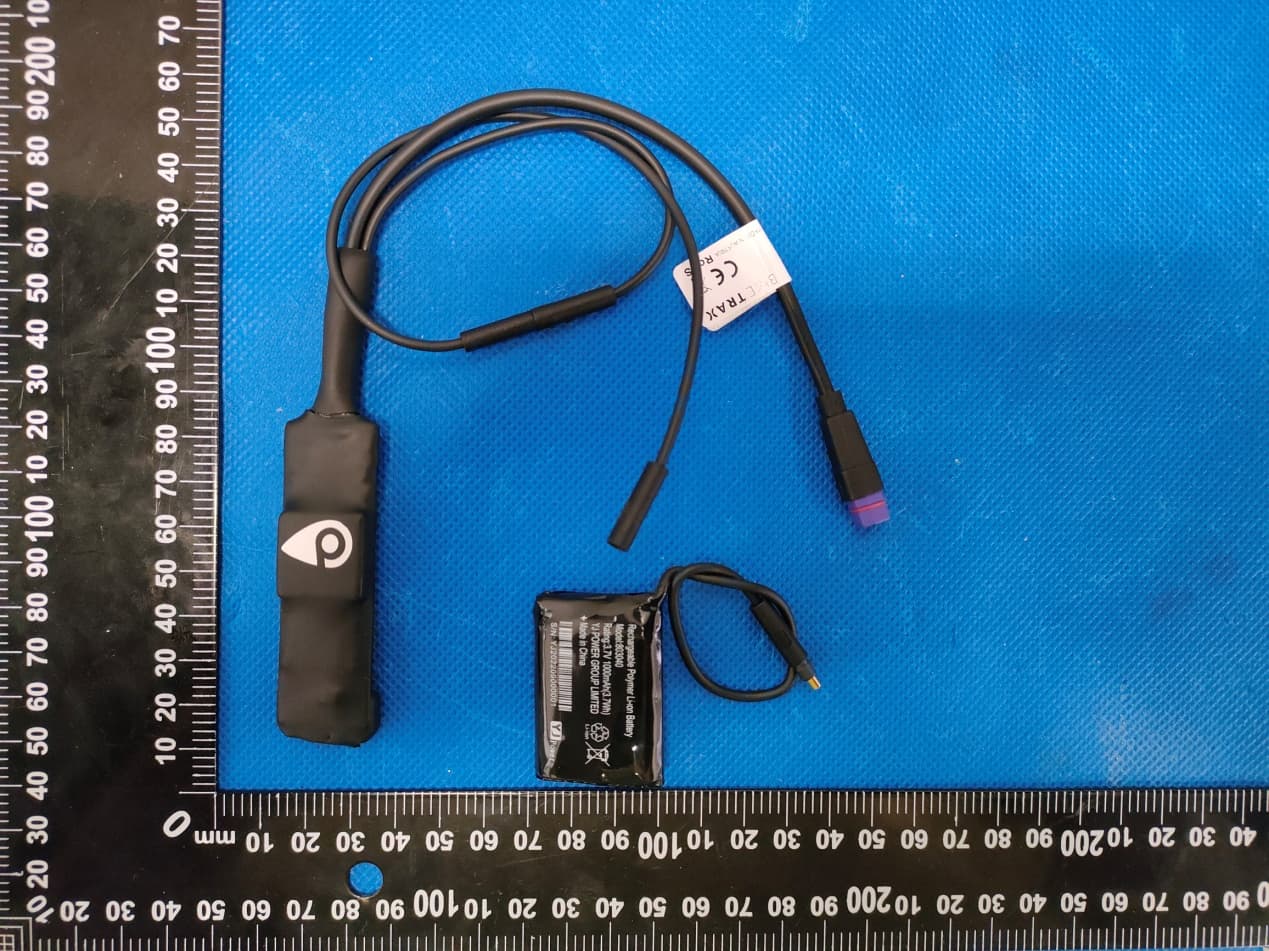
Click to zoom
Application Details
- Equipment Class
- DTS - Digital Transmission System
- Date of Grant
- Jul 05, 2023
- Application Purpose
- Original Equipment
- Date of Application
- Jul 05, 2023
- Equipment Note
- GPS Tracker
- Frequency Range
- 2402.00000000 - 2480.00000000
- Company
- PowUnity GmbH
- Country
- Austria
Documents & Files
Document Text
Text extracted from the exhibit documents filed with the FCC. Open a document above to read the original.
Users Manual
POWUNITY.COM DE ELEKTROMAGNETISCHE VERTRÄGLICHKEIT Sehr starke Magnetfelder (z.B. Trans- formatoren) müssen unbedingt gemie- den werden, da sonst Abweichungen in der Übertragung entstehen können. Das Nichtbeachten dieser Hinweise kann zu Störungen oder zu Beschä- digung des PowUnity GPS-Tracker (BikeTrax) führen. GEFAHREN FÜR KINDER UND HILFSBEDÜRFTIGE PERSONEN Dieses Gerät ist nicht dafür bestimmt, von Personen (einschließlich Kinder) mit eingeschränkten physischen, sen- sorischen oder geistigen Fähigkeiten oder mangelnder Erfahrung und/oder mangelndem Wissen benutzt zu wer- den, es sei denn, sie werden durch ei- ne für ihre Sicherheit zuständige Per- son beaufsichtigt oder erhielten von ihr Anweisungen, wie das Gerät zu be- nutzen ist. Hinweis: In manchen Ländern und Re- gionen gibt es Gesetzte über die digi- tale Positionsbestimmung und Ortung von Personen, Tieren und/ oder Ge- genständen. Der Besitzer bzw. Benut- zer des PowUnity GPS-Trackers (Bike- Trax) ist allein dafür verantwortlich, nicht gegen derartige Gesetze oder Vorschriften zu verstoßen. Schalten Sie Ihren GPS-Tracker aus, wenn Sie Ihn an Bord eines Flugzeuges bringen. AKKUBETRIEB Der PowUnity GPS-Tracker (BikeTrax) wird über einen wieder aufladbaren Li-Polymer-Akku betrieben. Der Akku des PowUnity GPS-Track- ers (BikeTrax) kann nur durch einen von PowUnity zur Verfügung gestell- ten Original Akku ersetzt werden. Der PowUnity GPS-Tracker (Bike- Trax) Akku darf nicht zerlegt, ver- brannt oder kurzgeschlossen wer- den. Lagern oder transportieren Sie den Akku nicht gemeinsam mit Metall- objekten, die einen Kurzschluss der positiven und negativen Pole verur- sachen können. Setzen Sie den PowUnity GPS- Tracker (BikeTrax) nie großer Hitze, wie Sonne, Feuer oder ähnlichen aus. Halten Sie den Akku von Wasser fern. Laden Sie den Akku nie in der Nähe einer Hitzequelle oder unter direk- ter Sonneneinstrahlung. Bohren Sie nicht in den Akku, vor al- lem mit keinen Metallobjekte, schla- gen Sie nicht mit einemHammer da- rauf oder zerstören und zerbrechen Sie diesen anderweitig nicht. Falls Flüssigkeit aus dem Akku aus- tritt, vermeiden Sie direkten Kontakt damit und entsorgen Sie den Akku sachmäßig. Halten Sie den Akku außer Reich- weite von Kindern und Haustieren, um ein Verschlucken zu vermeiden. Ein Verschlucken kann zu Verbren- nungen, Gewebeperforation und zum Tod führen. Starke Verbrennun- gen können innerhalb von 2 Stunden nach Verschlucken auftreten. Sollte eine Zelle oder ein Akku verschluckt worden sein, suchen sie umgehend eine(n) Arzt/Ärztin oder Tierarzt/ Tierärztin auf. Überhitzt der Akku oder verformt er sich während des Ladens oder wäh- rend das Geräts genutzt wird, ent- fernen Sie Ihn umgehend vom Tra- cker oder Ladegerät und verwenden Sie Ihn nicht mehr. Laden Sie den Akku des Pow- Uni- ty GPS-Tracker (BikeTrax) nur über den mitgelieferten BikeTrax GPS- Tracker. Wird der Akku anders gela- den, kann es zu Überhitzung, Explo- sion oder Feuer führen. Verwenden Sie zum Laden des GPS- Tracker kein Schnellladegerät, da der Akku dadurch Schaden nehmen kann. Der Tracker sollte nur bei Tempera- turen zwischen 0°C und +40°C be- nutzt werden. Bei Missachtung dieser Hinwei- se kann es zur Verkürzung der Be- triebsdauer des eingebauten Akkus, zu Schäden am PowUnity GPS- Tracker und den damit verbunden Geräten kommen. EU-KONFORMITÄTSERKLÄRUNG Hiermit erklärt PowUnity GmbH, dass der Funkanlagentyp BT41-01 der Richtlinie 2014/53/EU entspricht. Der vollständige Text der EU Konformi- tätserklärung ist unter der folgenden Internetadresse verfügbar: https:// service.powunity.com/euro/compli- ance/ HINWEISE ZU ENTSORGUNG UND RECYCLING Das oben gezeigte Symbol weist dar- auf hin, dass dieses Produkt und/oder die Batterie getrennt vom Hausmüll entsorgt werden muss. Achte beim Entsorgen dieses Produkts und/oder der Batterie auf die Einhaltung der umweltrechtlichen Bestimmungen und Regelungen deiner Region. Aus- kunft für eine fachgerechte Entsor- gung erteilt dir gerne auch deine kom- munale Stelle. FCC-WARNUNG: Jegliche Änderungen oder Modifika- tionen, die nicht ausdrücklich von der für die Konformität verantwortlichen Partei genehmigt wurden, kann dazu führen, dass der Benutzer die Berech- tigung zum Betrieb der Funkanlage verliert. Diese erfüllt die Anforderun- gen von Teil 15 der FCC-Bestimmun- gen. Der Betrieb unterliegt den fol- genden zwei Bedingungen: GPS Sicherheitsinformationen GPS Safety Information (1) Dieses Gerät darf keine schädli- chen Interferenzen verursachen, und (2) dieses Gerät muss alle empfan- genen Störungen akzeptieren, ein- schließlich Störungen, die einen un- erwünschten Betrieb verursachen können. Diese Funkanlage erfüllt die staatli- chen Anforderungen für die Belastung durch Funkwellen. Die Richtlinien be- ruhen auf Standards, die von unabhän- gigen wissenschaftlichen Organisatio- nen durch regelmäßige und gründliche Auswertung wissenschaftlicher Stu- dien entwickelt wurden. Die Standards beinhalten eine erhebli- che Sicherheitsspanne, um die Sicher- heit aller Personen unabhängig von Al- ter und Gesundheit zu gewährleisten. Zur Einhaltung der FCC-Richtlinien zur HF-Belastung sollte dieses Gerät in einem Mindestabstand von 20 cm zu dem Körper installiert und betrie- ben werden. Dieses Gerät und die zu- gehörige(n) Antenne(n) dürfen nicht zusammen mit anderen Antennen oder Sendern aufgestellt oder betrie- ben werden. HINWEIS: Diese Funkanlage wurde getestet und erfüllt die Grenzwerte für die Klasse B gemäß Teil 15 der FCC-Bestimmun- gen. Diese Grenzwerte sind so aus- gelegt, dass sie einen angemessenen Schutz gegen schädliche Störungen in einem Wohnbereich sicherstellen. Die Funkanlage erzeugt und verwendet HF-Signale und kann diese auch aus- strahlen und kann, wenn es nicht ge- mäß den Anweisungen installiert und verwendet wird, Störungen des Funk- verkehrs verursachen. Es kann jedoch nicht garantiert werden, dass bei einer bestimmten Installation keine Störun- gen auftreten. Wenn die F…
Text truncated - open the document above for the full version.
Attestation Statements
PowUnity GmbH 2.911 (d)(5)(i) Equipment Type Attestation v1.2 Section 2.911(d)(5)(i) Certification – Equipment Type Company name: PowUnity GmbH Address: Feldstrasse 9d Innsbruck, 6020 Austria Product Name: GPS Tracker FCC ID: 2A2FCBT4101 Model(s): BT41-01, T4101-03-04 2.911(d)(5)(i) Equipment Type We, [PowUnity GmbH] (“the applicant”) certify that the equipment for which authorization is sought through certification is not: Prohibited from receiving an equipment authorization pursuant to § 2.903; of the FCC rules. Identified as an equipment type in the “Covered List” NOTE 1 Yours sincerely, Name: Stefan Sinnegger Date: Jun. 28, 2023 Title: Managing director Company name: PowUnity GmbH Signature: NOTE 1 “Covered List ”; is the List of Equipment and Services Covered By Section 2 of The Secure Networks Act, available at https://www.fcc.gov/supplychain/coveredlist References; 1) 986446 D01 Covered Equipment v01 https://apps.fcc.gov/oetcf/kdb/forms/FTSSearchResultPage.cfm?switch=P&id=325672 2) Federal Register document 2022-28263 published on 02/06/23 https://www.federalregister.gov/documents/2023/02/06/2022-28263/protecting-against-national-security-threats-to-the-com munications-supply-chain-through-the
Attestation Statements
PowUnity GmbH 2.911 (d)(5)(ii) Applicant Attestation v1.3 Section 2.911(d)(5)(ii) Certification – Applicant (Covered List ) Company name: PowUnity GmbH Address: Feldstrasse 9d Innsbruck, 6020 Austria Product Name: GPS Tracker FCC ID: 2A2FCBT4101 Model(s): BT41-01, T4101-03-04 2.911(d)(5)(ii) Applicant filing We, [PowUnity GmbH] (“the applicant”) certify that, as of the date of the filing of the application, the applicant is not identified NOTE 1 on the “Covered List” NOTE 2 ,established pursuant to §1.50002 of this chapter, as an entity producing covered communications equipment. Yours sincerely, Name: Stefan Sinnegger Date: Jun. 28, 2023 Title: Managing director Company name: PowUnity GmbH Signature: NOTE 1 Delete option not applicable to this application. NOTE 2 “Covered List ”; is the List of Equipment and Services Covered By Section 2 of The Secure Networks Act, available at https://www.fcc.gov/supplychain/coveredlist References; 1) 986446 D01 Covered Equipment v01 https://apps.fcc.gov/oetcf/kdb/forms/FTSSearchResultPage.cfm?switch=P&id=325672 2) Federal Register document 2022-28263 published on 02/06/23 https://www.federalregister.gov/documents/2023/02/06/2022-28263/protecting-against-national-security-threats-to-the-com munications-supply-chain-through-the
Cover Letter(s)
PowUnity GmbH Agent Authorization Company: PowUnity GmbH Address: Feldstrasse 9d Innsbruck, 6020 Austria Product Name: GPS Tracker Model Number(s): BT41-01, T4101-03-04 Product Description: GPS Tracker We authorize MiCOM Labs Inc., 575 Boulder Court, Pleasanton, California 94566, USA, to act on our behalf on all matters concerning the certification of above named equipment. We declare that MiCOM Labs Inc. is allowed to forward all information related to the approval and certification of equipment to the regulatory agencies as required and to discuss any issues concerning the approval application. Any and all acts carried out by MiCOM Labs on our behalf shall have the same effect as acts of our own. Signature: Date: Jun. 28, 2023 Name: Stefan Sinnegger Title: Managing director Company: PowUnity GmbH
Cover Letter(s)
PowUnity GmbH Office of Engineering Technology Federal Communications Commission 7435 Oakland Mills Road Columbia, MD 21046 USA Date: Jun. 28, 2023 Subject; Request for Confidentiality FCC ID: 2A2FCBT4101 To Whom It May Concern, Pursuant to the provisions of the Commission’s rules Title 47 Sections §0.457 and §0.459, we are requesting the Commission to withhold the following attachment(s) as confidential documents from public disclosure indefinitely. These documents contain detailed system and equipment descriptions and are considered as proprietary information in operation of the equipment. The public disclosure of these documents might be harmful to our company and would give competitors an unfair advantage in the market. Schematic Diagram Block Diagram Parts List Operational Description Tune-up Procedure In additional to above mentioned documents, in order to comply with the marketing regulations in Title 47 CFR §2.803 and the importation rules in Title 47 CFR §2.1204, while ensuring that business sensitive information remains confidential until the actual marketing of newly authorized devices, we request Short Term Confidentiality of the following attachment(s); External Photos Test Setup Photos Internal Photos User Manual For 45 days, pursuant to Public Notice DA 04-1705. OR For 180 days pursuant to KDB 726920 D01. It is our understanding that all measurement test reports, FCC ID label format and correspondence during the certification review process cannot be granted as confidential documents and this information will be available for public review once the grant of equipment authorization is issued. Sincerely, Signature: Name: Stefan Sinnegger Title: Managing director
Cover Letter(s)
PowUnity GmbH Model Difference Declaration To Whom It May Concern, We, PowUnity GmbH (GPS Tracker) ; Model Number: BT41-01, T4101-03-04; All model’s the function, software and electric circuit are the same, only with a product color and model named different. Test sample model: BT41-01. Please contact me if you have any question. Signature: Date: Jun. 28, 2023 Name: Stefan Sinnegger Title: Managing director
External Photos
Annex A External Photos Test Model No.: BT41-01 Page 1 of 4 Test Model No.: BT41-01 Page 2 of 4 Test Model No.: BT41-01 Page 3 of 4 Test Model No.: BT41-01 Page 4 of 4
ID Label/Location Info
FCC ID LABEL: Ca. 10mm x 20mm Label Location FCC ID: 2A2FCBT4101
Internal Photos
Annex B Internal Photo Test Model No.: BT41-01 Page 1 of 3 4G Antenna Test Model No.: BT41-01 Page 2 of 3 Test Model No.: BT41-01 Page 3 of 3 BT Antenna
RF Exposure Info
RF Exposure evaluation FCC ID: 2A2FCBT4101 1. Applicable Standard According to §1.1307(b)(1), systems operating under the provisions of this section shall be operated in a manner that ensures that the public is not exposed to radio frequency energy level in excess of the Commission’s guidelines. According to §1.1310 and §2.1091 RF exposure is calculated. KDB447498 v06: Mobile and Portable Devices RF Exposure Procedures and Equipment Authorization Policies. 2. Limit FCC: Systems operating under the provisions of FCC 47 CFR section shall be operated in a manner that ensures that the public is not exposed to radio frequency energy level in excess of the Commission’s guidelines. In accordance with 47 CFR FCC Part 2 Subpart J, section 2.1091 this device has been defined as mobile device whereby a distance of 0.2m normally can be maintained between the user and the device, and below RF Permissible Exposure limit shall comply with. In accordance with KDB447498D01 for Simultaneous transmission MPE test exclusion applies when the sum of the MPE ratios for all simultaneous transmitting antennas incorporated in a host device, based on the calculated/estimated, numerically modeled or measured field strengths or power density, is ≤ 1.0. The MPE ratio of each antenna is determined at the minimum test separation distance required by the operating configurations and exposure conditions of the host device, according to the ratio of field strengths or power density to MPE limit, at the test frequency. Either the maximum peak or spatially averaged results from measurements or numerical simulations may be used to determine the MPE ratios. Spatial averaging does not apply when MPE is estimated using simple calculations based on far-field plane-wave equivalent conditions. The antenna installation and operating requirements for the host device must meet the minimum test separation distances required by all antennas, in both standalone and simultaneous transmission operations, to satisfy compliance. Limits for Maximum Permissible Exposure (MPE)/Controlled Exposure Frequency Range(MHz) Electric Field Strength(V/m) Magnetic Field Strength(A/m) Power Density (mW/cm²) Averaging Time (minute) Limits for Occupational/Controlled Exposure 0.3 – 3.0 3.0 – 30 30 – 300 300 – 1500 1500 – 100,000 614 1842/f 61.4 / / 1.63 4.89/f 0.163 / / (100) * (900/f 2 )* 1.0 f/300 5 6 6 6 6 6 Limits for Maximum Permissible Exposure (MPE)/Uncontrolled Exposure Frequency Range(MHz) Electric Field Strength(V/m) Magnetic Field Strength(A/m) Power Density (mW/cm²) Averaging Time (minute) Limits for Occupational/Controlled Exposure 0.3 – 3.0 3.0 – 30 30 – 300 300 – 1500 1500 – 100,000 614 824/f 27.5 / / 1.63 2.19/f 0.073 / / (100) * (180/f 2 )* 0.2 f/1500 1.0 30 30 30 30 30 F=frequency in MHz *=Plane-wave equivalent power density 3. MPE Calculation Method FCC: Predication of MPE limit at a given distance Equation from page 18 of OET Bulletin 65, Edition 97-01 S=PG/4πR² Where: S=power density P=power input to antenna G=power gain of the antenna in the direction of interest relative to an isotropic radiator R=distance to the center of radiation of the antenna 4. Result Mode Minimum Separation Distance Output Power (Turn-up Procedure) Antenna Gain (Numeric) Power Density At 20 cm (mW/cm 2 ) Power Density Limit (mW/cm 2 ) MPE Ratios Test Results (cm) dBm mW LTE Band 2-M1 20.00 24.0 251.19 1.26 0.06294 1.0 0.06294 PASS LTE Band 4-M1 20.00 22.0 158.49 1.26 0.03971 1.0 0.03971 PASS LTE Band 5-M1 20.00 21.0 125.89 1.26 0.03155 0.549 0.05747 PASS LTE Band 12-M1 20.00 21.0 125.89 1.26 0.03155 0.466 0.06770 PASS LTE Band 13-M1 20.00 20.0 100.00 1.26 0.02506 0.518 0.04838 PASS LTE Band 18-M1 20.00 22.0 158.49 1.26 0.03971 0.543 0.07313 PASS LTE Band 19-M1 20.00 22.0 158.49 1.26 0.03971 0.553 0.07181 PASS LTE Band 25-M1 20.00 22.0 158.49 1.26 0.03971 1.0 0.03971 PASS LTE Band 26-M1 20.00 21.0 125.89 1.26 0.03155 0.543 0.05810 PASS LTE Band 66-M1 20.00 22.0 158.49 1.26 0.03971 1.0 0.03971 PASS LTE Band 85-M1 20.00 20.0 100.00 1.26 0.02506 0.519 0.04829 PASS LTE Band 2-NB2 20.00 23.0 199.53 1.26 0.05000 1.0 0.05000 PASS LTE Band 4- NB2 20.00 21.0 125.89 1.26 0.03155 1.0 0.03155 PASS LTE Band 5- NB2 20.00 21.0 125.89 1.26 0.03155 0.549 0.05747 PASS LTE Band 12- NB2 20.00 21.0 125.89 1.26 0.03155 0.466 0.06770 PASS LTE Band 13- NB2 20.00 22.0 158.49 1.26 0.03971 0.518 0.07666 PASS LTE Band 18- NB2 20.00 23.0 199.53 1.26 0.05000 0.543 0.09208 PASS LTE Band 19- NB2 20.00 23.0 199.53 1.26 0.05000 0.553 0.09042 PASS LTE Band 25- NB2 20.00 22.0 158.49 1.26 0.03971 1.0 0.03971 PASS LTE Band 66- NB2 20.00 22.0 158.49 1.26 0.03971 1.0 0.03971 PASS LTE Band 85- NB2 20.00 22.0 158.49 1.26 0.03971 0.465 0.08540 PASS BT 20.00 -2.08 0.62 1.78 0.00022 1.0 0.00022PASS Note: F/1500(F=frequency in MHz) Band 5: Power Density Limit (mW/cm2)=824/1500=0.549 mW/cm 2 Band 12: Power Density Limit (mW/cm2)=699/1500=0.466 mW/cm 2 Band 13: Power Density Limit (mW/cm2)=777/1500=0.518 mW/cm 2 Band 18: Power Density Limit (mW/cm2)= 814/1500=0.543 mW/cm 2 Band 19: Power Density Limit (mW/cm2)= 830/1500=0.553 mW/cm 2 Band 26: Power Density Limit (mW/cm2)=814/1500=0.543 mW/cm 2 Band 85: Power Density Limit (mW/cm2)=778.8/1500=0.519 mW/cm 2 Band 85-NB2: Power Density Limit (mW/cm2)=698/1500=0.465 mW/cm 2 5. Simultaneous transmission MPE Considerations According to KDB447498 :For mobile exposure host platform to qualify for simultaneous transmission MPE test exclusion, all transmitters and antennas in the host must be either evaluated for MPE compliance, by measurement or computational modeling, or qualify for the standalone MPE test exclusion in section 7.1. Simultaneous transmission MPE test exclusion applies when the sum of the MPE ratios for all simultaneous transmitting antennas incorporated in a host device, based on the calculated/estimated, numerically modeled or measured field strengths or power density, is ≤ 1.0. This means that: ∑ of MPE ratios ≤ 1.0 BT and LTE Simultaneous evaluatio…
Text truncated - open the document above for the full version.
Test Report
Page 1 of 41 Report No.: HK2302270554-22E FCC Test Report FCC PART 15 SUBPART C 15.247 Test report On Behalf of PowUnity GmbH For GPS Tracker Model No.: BT41-01, T4101-03-04 FCC ID: 2A2FCBT4101 Prepared For : PowUnity GmbH Feldstrasse 9d Innsbruck, 6020 Austria Prepared By : Shenzhen HUAK Testing Technology Co., Ltd. 1-2/F., Building B2, Junfeng Zhongcheng Zhizao Innovation Park, Heping, Fuhai Street, Bao’an District, Shenzhen, Guangdong, China Date of Test: Feb. 27, 2023 ~ Apr. 17, 2023 Date of Report: Apr. 17, 2023 Report Number: HK2302270554-22E Page 2 of 41 Report No.: HK2302270554-22E Test Result Certification Applicant’s name ................... : PowUnity GmbH Address .................................... : Feldstrasse 9d Innsbruck, 6020 Austria Manufacture's Name .............. : PowUnity GmbH Address .................................... : Feldstrasse 9d Innsbruck, 6020 Austria Product description Trade Mark: BikeTrax Product name ............................. : GPS Tracker Model and/or type reference .. : BT41-01, T4101-03-04 Standards ................................ : 47 CFR FCC Part 15 Subpart C 15.247 This publication may be reproduced in whole or in part for non-commercial purposes as long as the Shenzhen HUAK Testing Technology Co., Ltd. is acknowledged as copyright owner and source of the material. Shenzhen HUAK Testing Technology Co., Ltd. takes no responsibility for and will not assume liability for damages resulting from the reader's interpretation of the reproduced material due to its placement and context. Date of Test .............................................. : Date (s) of performance of tests ................ : Feb. 27, 2023 ~ Apr. 17, 2023 Date of Issue ............................................. : Apr. 17, 2023 Test Result ................................................. : Pass Prepared by: Project Engineer Reviewed by: Project Supervisor Approved by: Technical Director Page 3 of 41 Report No.: HK2302270554-22E Contents Page 1 Test Summary ................................................................................................................................................ 5 1.1 Test Description ......................................................................................................................................... 5 1.2 Measurement Uncertainty ......................................................................................................................... 6 1.3 Information of the Test Laboratory ............................................................................................................ 6 2 General Information ....................................................................................................................................... 7 2.1 General Description of EUT ...................................................................................................................... 7 2.2 Description of Test Conditions .................................................................................................................. 9 2.3 Description of Test Setup ........................................................................................................................ 10 3 Equipments List for All Test Items ............................................................................................................. 11 4 Test Result .................................................................................................................................................... 13 4.1 Antenna Requirement.............................................................................................................................. 13 4.2 Conduction Emissions Measurement ...................................................................................................... 14 4.3 Radiated Emissions Measurement .......................................................................................................... 17 4.4 Maximum Output Power Measurement ................................................................................................... 26 4.5 Power Spectral Density ........................................................................................................................... 27 4.6 6db Bandwidth ......................................................................................................................................... 30 4.7 Occupied Bandwidth ................................................................................................................................ 33 4.8 Band Edge ............................................................................................................................................... 34 4.9 Conducted Spurious Emissions .............................................................................................................. 36 5 Test Setup Photo ......................................................................................................................................... 40 6 Photos of the EUT ........................................................................................................................................ 41 Page 4 of 41 Report No.: HK2302270554-22E ** Modified History ** Revision Description Issued Data Remark Revision 1.0 Initial Test Report Release Apr. 17, 2023 Jason Zhou Page 5 of 41 Report No.: HK2302270554-22E 1 Test Summary 1.1 Test Description Test Item Test Requirement Result Antenna Requirement §15.203/§15.247(b)(4) PASS Conducted Emission FCC Part 15.207 N/A Radiated Emissions FCC Part 15.205/15.209 PASS Maximum Peak Output Power FCC Part 15.247(b) PASS Power Spectral Density FCC Part 15.247(e) PASS 6dB Bandwidth & 99% Bandwidth FCC Part 15.247(a)(2) PASS Spurious RF Conducted Emission FCC Part 15.247(d) PASS Band Edge FCC Part 15.247(d) PASS Page 6 of 41 Report No.: HK2302270554-22E 1.2 Measurement Uncertainty All measurements involve certain levels of u…
Text truncated - open the document above for the full version.
Test Report
Product Name WiFi terminal patch antenna Product Code ARWBT3216P Antenna Technical Specification 一、Overview This antenna is a WiFi terminal patch antenna, working frequency is 2400-2500MHz, widely used in WIFi products, Bluetooth headset and audio, PAD, mobile phone multi-band antenna. It is widely used in WIFi products, Bluetooth headset and audio, PAD, cell phone multi-band antennas on various devices, using small size SMD chip design. 二、Technical Requirements 2.1 Antenna Indicators Technical Requirements Antenna Indicators 1 工作频率 Frequency 2400MHz-2500MHz 2 回波损耗 ReturnLoss -10dB (典型值Typical values) 3 天线效率 Efficiency 80% (典型值 Typical values ,在 80*40mm 底板上 测试 Testing on the base plate) 4 平均增益 AverageGain -3.6 dBi (典型值 Typical values) 5 峰值增益 PeakGain 2.5dBi (峰值Peak) 6 输出驻波比 OutputVSWR ≤2 7 极化 Polarization 线极化 ( Linearpolarization) 8 阻抗 Impendance 50 2.2 环境适应性 Environmental adaptability 1 工作温度 Operating temperature -25°C ~ +70°C 2 存储温度 Storage temperature -25°C ~ +85°C 3 相对湿度 Relative Humidity 10% ~95% 2.3 机械特性 Mechanical properties 1 天线尺寸 Demention 3.2*1.6*0.5mm 2 天线材料 Material 陶瓷 Ceramics 图Pic2 参考测试电路板 Reference test board 2、天线效率和增益Antenna efficiency and gain: 3、天线辐射方向图Antenna radiation direction map: 五、Antenna welding conditions 1、Solder flux ① Use rosin flux, prohibit the use of halide content from 0.2wt% of the strong acid flux. ② Use pure tin solder 2、Reflow soldering conditions When preheating, the temperature difference between the product surface temperature and the solder temperature should not exceed 150°C. When cooling after soldering, the temperature difference between the product surface temperature and the solvent temperature should not exceed 100°C. Insufficient preheating may cause cracks on the surface of the product, resulting in a decline in product quality. ● Standard reflow profile 3、Manual rework When using a soldering iron for manual soldering, the following conditions must be strictly observed 六、Packaging ①Braided belt and pulley size : Unit:mm ②Package Quantity: 6000 PCS / Tray 七、Custody ① . Storage period Within six months from the time of factory inspection, the product can be used; the inspection time can be confirmed by the inspection number marked on the outside of the package; If the time exceeds six months, the welding performance should be checked before use. ②. Storage conditions The storage room where the goods are stored should meet the following conditions Temperature: 10 ~ 40°C Humidity: 30 to 70% relative humidity Extreme changes in temperature and humidity are not allowed. It is forbidden to store the product in corrosive substances such as sulfur, chlorine, or acid, as this will cause oxidation of the ends and reduce the weldability. To avoid the influence of moisture, dust and other substances, the product should be stored on the shelf. The product should be stored in a warehouse to avoid thermal shock, vibration, and direct light, etc. The product should be sealed and packed.
Test Setup Photos
Radiated Emissions
Contact Information
Applicant
Stefan Sinnegger
Technical Contact
Test Firm
Shenzhen HUAK Testing Technology Co., Ltd.Jason Zhou
[email protected]86-755-23029901
Technical Specifications
| # | Rule Parts | Frequency Range | Power Output |
|---|---|---|---|
| 1 | 15C | 2.40 GHz - 2.48 GHz | 620.00 µW |
Other Applications from PowUnity GmbH
2A2FC-T202T201
Jul 14, 2021GPS TRACKER
Equipment Class
DSS - Part 15 Spread Spectrum Transmitter