2A2FMP3PWS010PostureSense
Posture360 Inc.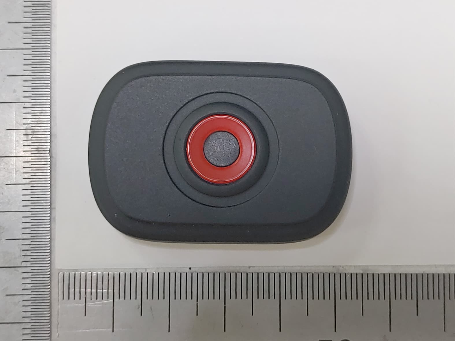
Click to zoom
Application Details
- Equipment Class
- DTS - Digital Transmission System
- Date of Grant
- Aug 11, 2021
- Application Purpose
- Original Equipment
- Date of Application
- Aug 11, 2021
- Equipment Note
- PostureSense
- Frequency Range
- 2402.00000000 - 2480.00000000
- Company
- Posture360 Inc.
- Country
- South Korea
Documents & Files
Document Text
Text extracted from the exhibit documents filed with the FCC. Open a document above to read the original.
Users Manual
본�제품은�전용�셔츠나�전용�밴드에�삽입하여�사용하는�웨어러블 디바이스�입니다. 실시간�사용자의�자세�변화를�측정하고�나쁜�자세가�감지되면 진동으로�알림을�줍니다. 알림을�받은�사용자는�스스로�나쁜�자세를�바로�잡고�바른�자세�습관을 형성하는데�도움을�받을�수�있습니다. · · · 안전을�위한�주의사항 주의사항 PostureSense는�전기�에너지를�사용하므로�부적절한�방법으로 사용하면�부상을�일으킬�수�있습니다. PostureSense는�의료기기가�아니므로�질병의�진단, 치료, 예방을 목적으로�제조되지�않았습니다. 관련�질환자의�경우, PostureSense를�사용하는�것이�영향을 미친다고�생각되면�의사와�상의하시기�바랍니다. 진동�알림이�방해가�되는�작업�중에는�데이터가�정확하게�측정되지 않으니�가급적�사용을�자제해주시기�바랍니다. PostureSense는�방수가�되지�않으니�습기와의�접촉을�피하시고 물이�스며들지�않도록�주의해�주시기�바랍니다. 제품�손상과�베터리�수명단축�방지를�위하여�적정�사용�온도�및�보관 온도(-10°C ~ 45°C)를�지켜주시기�바랍니다. 내장�배터리�관련�주의사항 내장된�배터리는�사용자가�교체할�수�없으며�열을�가하거나�강제로�센서 모듈의�뚜껑을�열면�보증�서비스를�받을�수�없고�위험에�노출될�수 있습니다. 제품 A/S 관련�문의 A/S 문의�시에는�제품�모델명, 고장�상태, 연락처를�알려�주세요. · 포스처360 대표�전화 : 1522-3602 · 모바일�상담 : 카카오톡�플러스친구 ‘포스처360’ · · · · · · 사용�설명서의�내용은�제품의�소프트웨어�버전�또는�제조사의�사정에�따라�다를�수 있으며, 사용자에게�통보�없이�일부�변경될�수�있습니다. * FCC Rules This device complies with part 15 of the FCC Rules. Operation is subject to the following two conditions: (1) This device may not cause harmful interference, and (2) this device must accept any interference received, including interference that may cause undesired operation. Note : This equipment has been tested and found to comply with the limits for a Class B digital device, pursuant to part 15 of the FCC Rules. These limits are designed to provide reasonable protection against harmful interference in a residential installation. This equipment generates, uses and can radiate radio frequency energy and, if not installed and used in accordance with the instructions , may cause harmful interference to radio communications. However, there is no guarantee that interference will not occur in a particular installation. If this equipment does cause harmful interference to radio or television reception, which can be determined by turning the equipment off and on, the user is encouraged to try to correct the interference by one or more of the following measures: Changes or modifications not expressly approved by the party responsible for compliance could void the user's authority to operate the equipment. This device complies with FCC RF exposure requirement. · · · · Reorient or relocate the receiving antenna. Increase the separation between the equipment and receiver. Connect the equipment into an outlet on a circuit different from that to which the receiver is connected. Consult the dealer or an experienced radio/TV technician for help. Quick Guide 간단�사용�설명서 POSTURE360 POSTURE360 이�보증서는�대한민국에서만�사용이�가능합니다. 제�품�보�증�서 포스처360에서는�품목별�소비자�분쟁해결기준에�따라�아래와�같이�제품에�대한�보증을�실시합니다. 제품에 고장�이�발생하면�구입처�또는 1522-3602로�전화주세요. 수리�교체�후�불량부품은�재사용�방지�및�안전을�위해 전량�회수하는�것을�원칙으로�하고�있으며, 일부�수리의�경우�기기등록이�필요할�수�있습니다. 모델명 구입처 *제품보증기간은 1년, 부품보유기간은 4년입니다. 제품명 구입일 구매금액 무상�서비스 제품보증기간�이내에�정상적인�사용�상태에서�발생한�고장의�경우�무상�서비스를�받을�수�있습니다.(비�고장성, 과실은�제외) 이�제품을�영업�용도로�전환하여�사용할�경우�보증기간은 6개월로�단축되고, 환급�시�구입가로 환급되며�구입�시�영수증을�제출해�주셔야�합니다 중요한�수리º 란�제품을�분해하여�부품�교체를�하여야�정상적인�사용을�할�수�있는�상태 부품보유 기간내 정상적인 사용조건 에서�성능, 기능상의 고장� 발생 소비자�피해유형 보상내용 소비자가�수리�의뢰한�제품을 사업자가�분실 부품보유�기간�이내�수리용�부품을 보유하고�있지않아�수리가�불가 동일한�원인으로�고장이 3회까지�발생 서로�다른�원인으로�고장이 5회�발생 제품보증기간�이내 구입�후, 10개월이내 중요한�수리º 시 제품�교환 or 환급 해당없음 유상수리 유상수리 유상수리 정액�감가상각한�금액에 10%를�가산하여�환급 정액�감가상각한�금액에 구입가의 10%를�가산하여 환급 구입�후, 1개월이내 중요한�수리º 시 제품�교환 or 무상수리 제품�교환�불가시환급 동일한�원인으로�고장이 2회까지�발생무상수리 제품교환 or 환급 제품보증기간�이후 수리 가능 주식회사�포스처360 특정�소출력�무선기기 (무선�데이터�통신�시스템용�무선기기) / P3PS-101BK PostureSense DC3.7V Bluetooth V5.2 BLE (1Mbps) 2402MHz ~ 2480MHz 주식회사�포스처360 / 한국 R-R-PXV-P3PS-101BK 상호명 기자재의�명칭(모델명) 제품명 정격 블루투스�무선사양 제조자 / 제조국 KC 인증번호 구성품�확인 · 센서· 간단�사용�설명서· 밴드 각�부분의�명칭 제품�개요 on/off 버튼 센서 LED 밴드�안쪽�충전�단자�홀더 고정�프레임 앞면 뒷면 밴드 충전�단자 (USB Type-C) 제품�구성 정액�감가상각�잔여금액에 10%를�가산하여�환급 제품보증기간�이후 · · · · · · · ※ · · · 1. 소비자의�과실로�고장이�난�경우 사용상의�부주의(침수, 파손, 손상)으로�고장이�발생한�경우 소비자가�데이터를�임의�조작하여�수리를�한�경우 당사에서�미지정한�소모품, 엑세서리를�사용하여�고장이�발생한�경우 사용�설명서의�주의사항을�지키지�않아�고장이�발생한�경우 2. 그�밖의�경우 천재지변(화재, 염해, 수해, 낙뢰등)에�의해�고장이�발생한�경우 소모성�부품(배터리, 커버등의�부착물)의�수명이�다한�경우 제품�보증기간�이내�부품의�고장이�발생하더라도�소비자�과실이�함께�발견된�경우 아래와�같은�경우�서비스가�거부될�수�있습니다. 임의로�개조, 변조, 복제하거나�사제(모조)부품을�사용하거나�소비자가�회수해�간�미반납�부품으로�재수리를 요구하는�경우 동일�제품을�반복해서�수리�요구하는�경우�등을�포함하여�수리�외�다른�목적의�수리�요구로�추정되는�경우 구입�또는 A/S 당시의�부품이�아닌�다른�부품으로�교체된�상태인�경우 유상�서비스 소비자�피해유형 보상내용 제품보증기간�이내 수리가�가능한�경우 소비자의 고의과실로 인한�고장�발생 유상수리 유상�수리에�해당하는�금액 징수�후�제품�교환�또는�환급 수리가�불가한�경우 유상수리 This product is a wearable device that is inserted into a dedicated shirt or dedicated band. It measures the user’s posture changes in real time and alerts them with vibrations when bad posture is detected. Users who receive notifications can correct their bad posture and form good posture habits. Composition Product overview 제품�사용법 Posture360 앱�설치하기 1. 2. 3. 앱스토어에서 ‘Posture360 앱’을�검색하여�앱을�설치합니다. 앱이�설치되면�클릭하여�앱을�연�뒤�필요한�정보를�입력하여 회원가입을�합니다. 회원가입이�완료되면�앱에서�지시하는�내용을�따라 PostureSense 와�앱을�연동합니다. PostureSense 착용하기 1. 2. 3. PostureWear를�착용해주세요. 밴드의�고정�프레임�뒷면에�센서의�충전단자가�아래로�향하도록 센서를�끼웁니다. PostureWear 센서�포켓에�센서의�밴드를�삽입합니다. 전원�켜기/끄기 · · · 본체의�전원�버튼을�누르시면�한번의�진동과�함께 LED에�빨간색 불빛이�들어오면서�전원이�켜집니다. 전원이�켜져�있는�경우 LED의�빨간색�불빛이�깜박입니다. 전원�버튼을 2초�이상�길게�누르시면�두번의�짧은�진동과�함께 LED 불빛이�깜박거리면서�전원이�꺼집니다. 본�제품을�사용하지�않을�경우(수평으로�놓인상태)에서는 2분�경과�후 3번의�짧은 진동이�울리며�추가 1분후�전원이�자동으로�꺼집니다. * 충전단자가 아래방향 Installing Posutre360 App 1. 2. 3. Search and download the Posture360 app from the app store. Install, launch the app and sign up. After registration is complete, follow the instructions in the app to link your PostureSense with the app. PostureSense usage 1. 2. 3. Wear the PostureWear shirt. Insert the sensor into the back of the band’s fixed frame with the sensor’s charging port facing down. Insert the band of the sensor into PostureWear's sensor pocket in the front. Front Back Charging port facing down 배터리�충전하기 1. 2. 3. PostureSense를�처음으로�사용하시는�경우, 반드시�배터리를�완전히 충전해주세요. * 충전을�위해�센서�밴드와�센서를�분리�후�충전�단자에 Type-C 케이블을�연결해�주세요. (USB 연결잭은�구성품에�포함되어�있지�않습니다.) 충전이�시작되면 LED에�빨간색�불이�들어오고�충전�중에는�빨간색 LED가�깜박거립니다. 충전이�완료되면�빨간색 LED가�깜박거리지�않습니다. Power on/off · · · To turn the PostureSense On press the sensor's power button. It will vibrate once and the LED wi…
Text truncated - open the document above for the full version.
Cover Letter(s)
Posture360 Inc. 3 Floor, 10, Garosu-gil, Gangnam-gu Seoul South Korea 06036 Date: 08/10/2021 Federal Communications Commission Authorization and Evaluation Division 1435 Oakland Mills Road Columbia, MD 21046 Request of Confidentiality FCC ID: 2A2FMP3PWS010 To Whom It may Concern: Pursuant to Sections 0.457 and 0.459 of the Commission`s Rules(CFR 47), and Section 552 (b) (4) of the Freedom of Information Act, Posture360 Inc.. hereby requests confidentiality and treatment of certain information accompanying this application. The materials contain trade secrets and proprietary information not customarily released to the public. The public disclosure of these matters might be harmful to the Applicant and provide unjustified benefits to its competitors. We are also hereby request Short-Term Confidentiality for 180 days after the grant as outlined in Public Notice DA 04-1705. This provision will give Posture360 Inc.. temporary confidentiality of commercially sensitive information prior to product release. The requested permanent and Short-Term Confidential exhibits are listed as follows: PERMANENT & SHORT-TERM CONFIDENTIAL LIST Exhibit Description PERMANENT 1 Block Diagram 2 Schematics 3 Part Lists 4 Operation Description 5 NA SHORT-TERM 6 Internal Photos 7 External Photos 8 Test-Setup Photos 9 User Manual The Applicant understands that pursuant to Rule 0.457, disclosure of this application and all accompanying documentations, where applicable, will not be public before the date of the Grant for this application. Sincerely, Contact Name: Esther Lee Title: Director
Cover Letter(s)
Posture360 Inc. 3 Floor, 10, Garosu-gil, Gangnam-gu Seoul South Korea 06036 Date: 08/10/2021 Federal Communications Commission Authorization and Evaluation Division 1435 Oakland Mills Road Columbia, MD 21046 Letter of Authorization We, the undersigned, hereby authorize Geunki Son of DT&C C o., Ltd. to act on our behalf in all manners relating to application for equipment authorization for FCC ID: 2A2FMP3PWS010 including signing of all documents relating to these matters. Any and all acts carried out by Geunki Son of DT&C C o., Ltd. on our behalf shall have the same affect as acts of our own. This authorization is valid until further written notice from Posture360 Inc.. “I, the undersigned, hereby certify that we are not subject to a denial of federal benefits, that includes FCC benefits, pursuant to Section 5301 of the Anti-Drug Abuse Act of 1988, 21 U.S.C. 853(a).” Sincerely, Contact Name: Esther Lee Title: Director
External Photos
FCC ID: 2A2FMP3PWS010 Copyright Ⓒ 2021, DT&C Co., Ltd. View 1 FCC ID: 2A2FMP3PWS010 Copyright Ⓒ 2021, DT&C Co., Ltd. View 2 FCC ID: 2A2FMP3PWS010 Copyright Ⓒ 2021, DT&C Co., Ltd. View 3 FCC ID: 2A2FMP3PWS010 Copyright Ⓒ 2021, DT&C Co., Ltd. View 4
ID Label/Location Info
FCC ID : 2A2FMP3PWS010 SAMPLE LABEL & LOCATION LABELLING REQUIREMENTS The Label shown shall be permanently affixed at a conspicuous location on the device and be readily visible to the user at the time of purchase. <Bottom Side> - The FCC label shown is representative of the label that will appear on the radio when in production. Other information may also be included on this label.
Internal Photos
FCC ID: 2A2FMP3PWS010 Copyright Ⓒ 2021, DT&C Co., Ltd. View 1 FCC ID: 2A2FMP3PWS010 Copyright Ⓒ 2021, DT&C Co., Ltd. View 2 FCC ID: 2A2FMP3PWS010 Copyright Ⓒ 2021, DT&C Co., Ltd. View 3 <Antenna> FCC ID: 2A2FMP3PWS010 Copyright Ⓒ 2021, DT&C Co., Ltd. View 4 <Battery> <Battery>
RF Exposure Info
FCC ID: RF feature Mode Transmitting Frequency(MHz) Test separation distance (mm) ANT Gain (dBi) Max. power with tune-up tolerance (dBm) Note1 Max. power with tune-up tolerance (mW) Power thresholds SAR test exclusion thresholds Bluetooth LE 1Mbps 2480.00 5.0 5.06 -0.50 0.8913 0.28 3.00 Note1. Conclusion : = [ ( 0.8913mW / 5mm ) ] X [ √2.48GHz ] = 0.28Note. The calculation result was rounded to two decimal place f or comparison. 2A2FMP3PWS010 Please refer to the operation description for Max tune-up. Standalone SAR test exclusion considerations SAR evaluation for general popul ation exposure conditions by me asurement or numerical simulation is not required KDB 447498 D01 clasue 4.3.1 Step 1) SAR test exclusion thresho lds for 100MHz to 6GHz at test separationn distances ≤ 50 mm [ ( max. power of channel, inclu ding tune-up tolerance, mW ) / ( min. test separation distance, mm ) ] · [ √f(GHz) ] ≤ 3.0 for 1g SAR and ≤ 7.5 for 10g extremity SAR Sample Calculation
Test Report
Report No.: DRTFCC2108-0083 FCC ID: 2A2FMP3PWS010 This test report is prohibited to copy or reissue in whole or in part without the approval of DT&C Co., Ltd. TRF-RF-238(06)210316 Pages: 2 / 39 Test Report Version Test Report No. Date Description Revised by Reviewed by DRTFCC2108-0083 Aug, 10. 2021 Initial issue SeungMin Gil JaeJin Lee Report No.: DRTFCC2108-0083 FCC ID: 2A2FMP3PWS010 This test report is prohibited to copy or reissue in whole or in part without the approval of DT&C Co., Ltd. TRF-RF-238(06)210316 Pages: 3 / 39 Table of Contents 1. General Information .................................................................................... 4 1.1. Description of EUT .......................................................................................................... 4 1.2. Declaration by the applicant / manufacturer ................................................................ 4 1.3. Testing Laboratory .......................................................................................................... 5 1.4. Testing Environment ....................................................................................................... 5 1.5. Measurement Uncertainty............................................................................................... 5 1.6. Test Equipment List ........................................................................................................ 6 2. Test Methodology ........................................................................................ 7 2.1. EUT Configuration ........................................................................................................... 7 2.2. EUT Exercise .................................................................................................................... 7 2.3. General Test Procedures ................................................................................................ 7 2.4. Instrument Calibration .................................................................................................... 7 2.5. Description of Test Modes.............................................................................................. 7 3. Antenna Requirements ............................................................................... 8 4. Summary of Test Results ........................................................................... 9 5. Test Result ................................................................................................. 10 5.1. Maximum Peak Conducted Output Power .................................................................. 10 5.1.1. Test Setup .................................................................................................................. 10 5.1.2. Test Procedures ........................................................................................................ 10 5.1.3. Test Results ............................................................................................................... 10 5.2. 6 dB Bandwidth ............................................................................................................. 13 5.2.1. Test Setup .................................................................................................................. 13 5.2.2. Test Procedures ........................................................................................................ 13 5.2.3. Test Results ............................................................................................................... 13 5.3. Power Spectral Density ................................................................................................. 16 5.3.1. Test Setup .................................................................................................................. 16 5.3.2. Test Procedures ........................................................................................................ 16 5.3.3. Test Results ............................................................................................................... 16 5.4. Unwanted Emissions (Conducted) .............................................................................. 19 5.4.1. Test Setup .................................................................................................................. 19 5.4.2. Test Procedures ........................................................................................................ 19 5.4.3. Test Results ............................................................................................................... 20 5.5. Unwanted Emissions (Radiated) .................................................................................. 28 5.5.1. Test Setup .................................................................................................................. 30 5.5.2. Test Procedures ........................................................................................................ 30 5.5.3. Test Results ............................................................................................................... 31 5.6. AC Power-Line Conducted Emissions ........................................................................ 32 5.6.1. Test Setup .................................................................................................................. 32 5.6.2. Test Procedures ........................................................................................................ 32 5.6.3. Test Results ............................................................................................................... 32 APPENDIX I .................................................................................................... 35 APPENDIX II ................................................................................................... 36 APPENDIX III .............................................................................................…
Text truncated - open the document above for the full version.
Test Setup Photos
FCC ID: 2A2FMP3PWS010 Copyright Ⓒ 2021, DT&C Co., Ltd. Test Setup photographs EUT Position: X-axis EUT Position: Y-axis EUT Position: Z-axis FCC ID: 2A2FMP3PWS010 Copyright Ⓒ 2021, DT&C Co., Ltd. Test Setup Photo of Radiated Measurement (0.009 ~ 30MHz) FCC ID: 2A2FMP3PWS010 Copyright Ⓒ 2021, DT&C Co., Ltd. Test Setup Photo of Radiated Measurement (Below 1GHz) FCC ID: 2A2FMP3PWS010 Copyright Ⓒ 2021, DT&C Co., Ltd. Test Setup Photo of Radiated Measurement (Above 1GHz) FCC ID: 2A2FMP3PWS010 Copyright Ⓒ 2021, DT&C Co., Ltd. Test Setup Photo of AC Line Conducted Measurement
Contact Information
Applicant
Esther Lee(Director)
Test Firm
Dt&C Co., Ltd.Lee Sang-Wook
Technical Specifications
| # | Rule Parts | Frequency Range | Power Output |
|---|---|---|---|
| 1 | 15C | 2.40 GHz - 2.48 GHz | 1.00 mW |