2A2FT-LK-GT6MWireless Transmitter
DongGuan RuiBo Electronic Technology Co., Ltd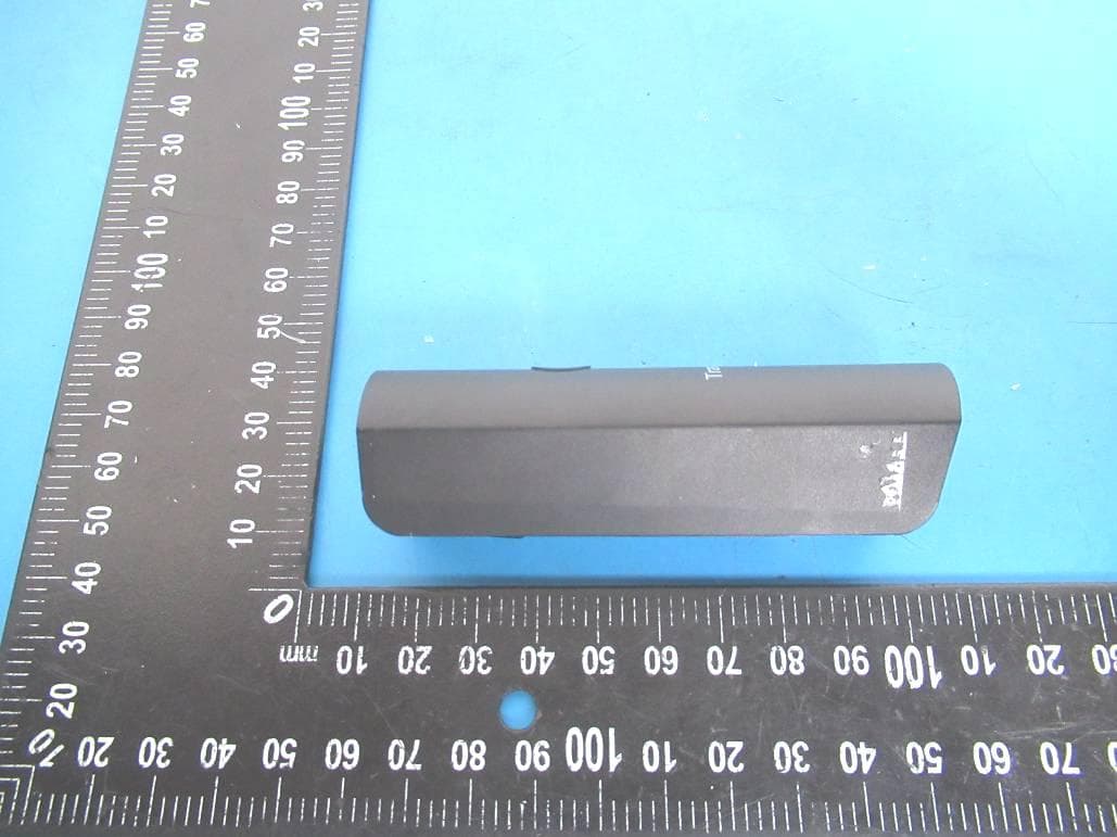
Click to zoom
Application Details
- Equipment Class
- DWM - Part 15 Wireless Microphone
- Date of Grant
- Jul 26, 2021
- Application Purpose
- Original Equipment
- Date of Application
- Jul 26, 2021
- Equipment Note
- Wireless Transmitter
- Frequency Range
- 651.00000000 - 693.00000000
- Country
- China
Documents & Files
Document Text
Text extracted from the exhibit documents filed with the FCC. Open a document above to read the original.
Users Manual
l A Please read the instructions carefully before using this product J wam,ng lnorderto邸!ucethe nsk of fire or electnc shocl s please do net put the equ,pment ,n the团nor ,n a hum�place N啪: Please do net d,sassem啦lhGeqU仰entwrthout阳Ull,olUI,There晔ncuser repa,rable paJ!ll, 芯啦Please hand tt to qualified repalnnan 1 Please use the attached chargmg cord for charg,ng 2 The dev,ce bu,lt-m hth1um batter ;, please do not put mto the water or heat source near 3 Th,s equ,pment does not have waterprooffunct,on, please do not put mto water or other hqu,d 4 Please do not attempt to repa,r the equ,pment by yourself, as opernng the cover may expose you to dangerous voltage pomts or other nsks. If the equ,pment needs to be repa,red, please g,ve ,t to quahfied mamtenance personnel for repa,r 5 If you do not use th,s product for a long t,me, you should unplug the charg,ng cord 6 Avoid trampling the power cord orstralnlng the socket and connecting device at the plug [A请在使用产品前详细阅读说明] 菩告·为了减 少火灾或者触电额危险,谐勿将本设备巴干雨中或者湖湿的 地方. 注意 诸勿私自拆卸本设备,内部没有用户可维修部件,请交给合格的维修人员处理 。 1诮使用附带的充电线进行充电· 2本设备内隘悝电池,诮勿投入火水中或热源的附近。 3本设备没有防水功能,谓勿投人水中或其他液体中。 4诮勿尝试自行维修本设备,因为打开盖子后可能会使您触碰到危险电压点或者其他风险, 如果本设备需要进行维修,谙交给合格的维修人员进行维修。 5如果您长时间不使用本产品时,应该拔掉充电线。 6避免电源线被踩踏或者在插头处插座和连接设备的位笠绷的太紧。 芯CE心呈 中国制造 心产品参数 接收灵敏度 < -110dbm@20dbs1nad 延 迟 <2ms _ >85d8 失真度 <0.05% 20~20KHz 传输距离 30~50m · 适用于所有6.35mm的音频接口设备 心入门 1 给无线系统充电--发射器和接收器正常使用时以及 充电时电揖显示. .当设备处千关机或开机时双击正面按谜则4个绿灯 显示当前电扭信息,3秒后熄灭. • 电噩指示灯,开机成功后,灯会从低到高逐渐增加 ,全部点亮后,再熄灭.正常工作时电池灯是熄灭 状态,节约电免· 卜斗,『l1�ii日1宁片, 25%电君 '"'"偿"'叮 JOO%电侄 第一个灯闪烁配农示 电侄力0·25%电侄此时 孚对发引器(按收器) 进行充电 小) 茫电状态显示,充电指示灯如下,拔下插头指示灯熄 闪烁 ,_,,,. 屯垦 25-50%屯霆50-75%屯盘75-700%屯日已充潇 · 插人USB充电线,可以通过USB接口给本机充电,在碌低电暨时充满约为 一 小左右. 2无线系统开机--发射器和接收器使用时状态灯显示。 · 发射器常用状态指示灯,开机后常亮,关机后灭 , 接收器开机后慢闪烁, 配对成功后常亮,关机后灭。 ·开机长按开机键,状态灯点亮后,松开,开机成功。 丿 ` � 小 1 @总酘按优 ·关机长按开机键,状态灯灭,松开,关机成功。 R.�;. 忒 正 面 甘面 `.`� ` i 3背面针孔状隐藏按键(示意图 a 位监), 是配对按键,第 一 次开机后,发射板和接收板 两个隐藏按键常按,状态指示灯快闪后松开,会自动进行配对,配对成功后,后续 开机不需要进行操作有记忆功能,下次开机自动配对,机器长期不使用电池完全耗 尽的情况下,需要芷新进行配对。 • 在发射板与接收板配对成功后,发射板开机键,轻按 一 下,状态灯闪烁,切换频道 总共有15个频道可以切换,接收板会自动切换接收频率,不需要揉作接收器。 • 当机器侦测到没有信号输人时,会自动降低功耗,让机器进入待机状态,延长续航 ,但仍保持无线连接状态。 正 反 Transmitter: audio head connected to electric guitar or microphone or mobile phone Audio hole and other equipment; Built in lithium battery, after collecting sound As a launcher Receiving device: audio head connected to power amplifier, audio and other equipment; within A lithium battery is installed, and the high-frequency signal is received and decoded through audio IC decodes into audio signal Suitable for all 6.35mm audio interface devices 芯CE心呈 MADE IN CHINA This equipment has been tested and found to comply with the limits for a Class B digital device, pursuant to part 15 of the FCC Rules. These limits are designed to provide reasonable protection against harmful interference in a residential installation. This equipment generates, uses and can radiate radio frequency energy and, if not installed and used in accordance with the instructions, may cause harmful interference to radio communications. However, there is no guarantee that interference will not occur in a particular installation. If this equipment does cause harmful interference to radio or television reception, which can be determined by turning the equipment off and on, the user is encouraged to try to correct the interference by one or more of the following measures: • Reorient or relocate the receiving antenna. • Increase the separation between the equipment and receiver. • Connect the equipment into an outlet on a circuit different from that to which the receiver is connected. • Consult the dealer or an experienced radio/TV technician for help. Caution: Any changes or modifications to this device not explicitly approved by manufacturer could void your authority to operate this equipment. This device complies with part 15 of the FCC Rules. Operation is subject to the following two conditions: (1) This device may not cause harmful interference, and (2) this device must accept any interference received, including interference that may cause undesired operation. The device has been evaluated to meet general RF exposure requirement.
Cover Letter(s)
DATE : 2021.07.23 Equipment Autorisation Division Federal Communications Commission 7435 Oakland Mills Road Columbia, MD 21046 FCC ID:_ 2A2FT-LK-GT6M Product Name:_ Wireless Transmitter Request for Confidentiality Pursuant to Sections 0.457 and 0.459 of the commissions rules, we hereby request that the following documents be held confidential: (List here the documents for which you are seeking confidentiality – for example ...) Schematics Block diagram Operation description These materials contain trade secrets and proprietary information and are not customarily released to the public. The public disclosure of this information might be harmful to the company and provide unjustified benefits to our competitors. Dated this 2021.07.23 By: Ken Zhang Signature Printed Title: Manager On behalf of : DongGuan RuiBo Electronic Technology Co., Ltd Telephone: +86-13434569405
External Photos
FCC ID: 2A2FT-LK-GT6M
ID Label/Location Info
2.0*0.8cm Label Location FCC ID: 2A2FT-LK-GT6M Wireless Transmitter Model No.: LK-GT6M
Internal Photos
FCC ID: 2A2FT-LK-GT6M ANT
RF Exposure Info
RF Exposure evaluation According to 447498 D01 General RF Exposure Guidance v06 The 1-g and 10-g SAR test exclusion thresholds for 100 MHz to 6 GHz at test separation distances ≤ 50 mm are determined by: [(max. power of channel, including tune-up tolerance, mW) / (min. test separation distance, mm)] ·[√f(GHz)] ≤ 3.0 for 1-g SAR and ≤ 7.5 for 10-g extremity SAR, where f(GHz) is the RF channel transmit frequency in GHz. Power and distance are rounded to the nearest mW and mm before calculation. The result is rounded to one decimal place for comparison. Worse case is as below: 651MHz -4.03dBm(0.4mW)output power (0.4mW /5mm)·[√0.651(GHz)]= 0.1 < 3.0 for 1-g SAR So, SAR evaluation is not required.
Test Report
FCC TEST REPORT FCC ID: 2A2FT-LK-GT6M On Behalf of DongGuan RuiBo Electronic Technology Co., Ltd Wireless Transmitter Model No.: LK-GT6M Prepared for : DongGuan RuiBo Electronic Technology Co., Ltd Address : Office Building A, Building A, Beizha Oriental Commercial Building, Humen Town, Dongguan City, Guangdong Province, 1602 Prepared By : Shenzhen Alpha Product Testing Co., Ltd. Address : Building i, No.2, Lixin Road, Fuyong Street, Bao’an District, 518103, Shenzhen, Guangdong, China Report Number : A2104158-C01-R01 Date of Receipt : June 18, 2021 Date of Test : July 8, 2021- July 12, 2021 Date of Report : July 13, 2021 Version Number : V0 Page 2 of 40 Report No.: A2104158-C01-R01 TABLE OF CONTENTS Description Page 1. Summary Of Standards And Results ---------------------------------------------------------------- 6 1.1. Description of Standards and Results ---------------------------------------------------------- 6 2. General Information ------------------------------------------------------------------------------------ 7 2.1. Description of Device (EUT) -------------------------------------------------------------------- 7 2.2. Accessories of Device (EUT) ------------------------------------------------------------------- 8 2.3. Tested Supporting System Details -------------------------------------------------------------- 8 2.4. Block Diagram of connection between EUT and simulators ------------------------------- 8 2.5. Test Mode Description --------------------------------------------------------------------------- 8 2.6. Test Conditions ------------------------------------------------------------------------------------ 9 2.7. Test Facility ---------------------------------------------------------------------------------------- 9 2.8. Measurement Uncertainty ----------------------------------------------------------------------- 9 2.9. Test Equipment List ---------------------------------------------------------------------------- 10 3. Spurious Emission --------------------------------------------------------------------------------------11 3.1. Test Standard ------------------------------------------------------------------------------------ 11 3.2. Test Limits --------------------------------------------------------------------------------------- 11 3.3. Test Procedure ----------------------------------------------------------------------------------- 11 3.4. Test Setup ---------------------------------------------------------------------------------------- 12 3.5. Test Results -------------------------------------------------------------------------------------- 13 4. Power Line Conducted Emission ------------------------------------------------------------------- 20 4.1. Test Standard ------------------------------------------------------------------------------------ 20 4.2. Test Limits --------------------------------------------------------------------------------------- 20 4.3. Test Procedure ----------------------------------------------------------------------------------- 20 4.4. Test Setup ---------------------------------------------------------------------------------------- 20 4.5. Test Results -------------------------------------------------------------------------------------- 21 5. RF Power Output Test -------------------------------------------------------------------------------- 22 5.1. Test Standard ------------------------------------------------------------------------------------ 22 5.2. Test Limit ---------------------------------------------------------------------------------------- 22 5.3. Test Procedure ----------------------------------------------------------------------------------- 22 5.4. Test Setup ---------------------------------------------------------------------------------------- 22 5.5. Test Results -------------------------------------------------------------------------------------- 23 6. EMISSION MASK Test ------------------------------------------------------------------------------ 24 6.1. Test Standard ------------------------------------------------------------------------------------ 24 6.2. Test limits ---------------------------------------------------------------------------------------- 24 6.3. Test Procedure ----------------------------------------------------------------------------------- 25 6.4. Test Setup ---------------------------------------------------------------------------------------- 25 6.5. Test Results -------------------------------------------------------------------------------------- 25 7. Bandwidth ----------------------------------------------------------------------------------------------- 28 7.1. Test Standard ------------------------------------------------------------------------------------ 28 7.2. Test limits ---------------------------------------------------------------------------------------- 28 7.3. Test Procedure ----------------------------------------------------------------------------------- 28 7.4. Test Setup ---------------------------------------------------------------------------------------- 28 7.5. Test Results -------------------------------------------------------------------------------------- 29 8. Frequency stability ------------------------------------------------------------------------------------ 31 8.1. Test Standard and Limit ------------------------------------------------------------------------ 31 8.2. Test Procedure ----------------------------------------------------------------------------------- 31 Page 3 of 40 Report No.: A2104158-C01-R01 8.3. Test Setup ---------------------------------------------------------------------------------------- 31 8.4. Test Results -------------------------------------------------------------------------------------- 31 9. Test Setup Photo --------------------------------------------------------------------------------------- 33 9.1. Photos of Radiated emission ------------------------------------------------------------------ 3…
Text truncated - open the document above for the full version.
Test Setup Photos
FCC ID: 2A2FT-LK-GT6M Photos of Radiated emission Photos of Conducted Emission test
Contact Information
Applicant
Ken Zhang(Manager)
Test Firm
Shenzhen Alpha Product Testing Co., LTD.Real Yak
[email protected]+86 755 29766001
Technical Specifications
| # | Rule Parts | Frequency Range | Power Output |
|---|---|---|---|
| 1 | 15C | 651 MHz - 693 MHz | 395.40 µW |