2A2IZ-RCS12ARemote Controller
Charlton & Jenrick Ltd.
Click to zoom
Application Details
- Equipment Class
- DSC - Part 15 Security/Remote Control Transmitter
- Date of Grant
- Jul 11, 2021
- Application Purpose
- Original Equipment
- Date of Application
- Jul 11, 2021
- Equipment Note
- Remote Controller
- Frequency Range
- 433.92000000 - 433.92000000
- Company
- Charlton & Jenrick Ltd.
- Country
- United Kingdom
Documents & Files
Document Text
Text extracted from the exhibit documents filed with the FCC. Open a document above to read the original.
Users Manual
User Instructions 1 Remote controller Model No.: RCS12A Please read the instructions carefully before use of this remote controller and retained for future reference. User Instructions 2 1. APPLIANCE DATA AND INPORTANCE WARNINGS 1.1 Appliance data Voltag.............................................3V DC Frequency..............................ASK 433.92 MHZ Hardware version: V4.0.1A Software version: RF290A-TX-V2.0 20201012 1.2 Importance warnings 1.2.1 FCC Statement: This device complies with Part 15 of the FCC Rules. Operation is subject to the following two conditions: (1) This device may not cause harmful interference, and (2) This device must accept any interference received, including interference that may cause undesired operation. Any Changes or modifications not expressly approved by the party responsible for compliance could void the user's authority to operate the equipment Note: This product has been tested and found to comply with the limits for a Class B digital device, pursuant to Part 15 of the FCC Rules. These limits are designed to provide reasonable protection against harmful interference in a residential installation. This product generates, uses, and can radiate radio frequency energy and, if not installed and used in accordance with the instructions, may cause harmful interference to radio communications. However, there is no guarantee that interference will not occur in a particular installation. If this product does cause harmful interference to radio or television reception, which can be determined by turning the equipment off and on, the user is encouraged to try to correct the interference by one or more of the following measures: —Reorient or relocate the receiving antenna. —Increase the separation between the equipment and receiver. —Connect the equipment into an outlet on a circuit different from that to which the receiver is connected. —Consult the dealer or an experienced radio/TV technician for help. The device has been evaluated to meet general RF exposure requirement. The device can be used in portabl e exposure condition without restriction. 1.2.2 IC Statement : This device complies with Industry Canada licence-exempt RSS standard(s). Operation is subject to the following two conditions: (1) this device may not cause interference, and (2) this device must accept any interference, including interference that may cause undesired operation of the device. Le présent appareil est conforme aux CNR d'Industrie Canada applicables aux appareils radioexempts de licence. L'exploitation est autorisée aux deux conditions suivantes : (1) l'appareil ne doit pas produire de brouillage, et (2) l'utilisateur de l'appareil doit accepter tout brouillage radioélectrique subi, même si le brouillage est susceptible d'en compromettre le fonctionnement. Under Industry Canada regulations, this radio transmitter may only operate using an antenna of a type and maximum (or lesser) gain approved for the transmitter by Industry Canada. To reduce potential radio interference to other users, the antenna type and its gain should be so chosen that the equivalent isotropically radiated power (e.i.r.p.) is not more than that necessary for successful communication. Conformément à la réglementation d'Industrie Canada, le présent émetteur radio peut fonctionner avec une antenne d'un type et d'un gain maximal (ou inférieur) approuvé pour l'émetteur par Industrie Canada. Dans le but de réduire les risques de brouillage radioélectrique à l'intention des autres utilisateurs, il faut choisir le type d'antenne et son gain de sorte que la puissance isotrope rayonnée équivalente (p.i.r.e.) ne dépasse pas l'intensité nécessaire à l'établissement d'une communication satisfaisante. User Instructions 3 The device has been evaluated to meet general RF exposure requirement. The device can be used in portabl e exposure condition without restriction. L'appareil a été évalué pour répondre aux exigences générales d'exposition aux RF. L'appareil peut être utilisé dans des conditions d'exposition portable sans restriction. 2. Operations User Instructions 4 2a. Manual Control Panel 2a.1 The manual controls on appliance are located at the upper right of appliance. 2a.2 Turning on the appliance with the main power switch on ‘—‘ position. A long beep will be heard. 2a.3 Press “LIGHTS ON/OFF” to turn on or turn off both the flame and fuel bed at the same time. 2b. Remote Controls The remote control should be left on a flat surface in the room where the appliance is installed and away from any direct flow of hot air. 2 2a.4 There are 3 flame colour options: Press “FLAME” button to select the colour of flame (3 kinds of flame colour with flame) or return to the OFF position. 2a.5 Press “FUEL BED” button to select the colour of fuel bed (14 kinds of fuel bed) or return to the OFF position. 1 Reset Button for Remote Control Flame setting button Mains Power (On/Off) Switch Heater Running Indicators All Lights Fuel bed 3 Time and Day Advance Timer Mode Battery Power On/ Off button setting button Note: The remote control will lose the memory for all function settings when the switch is set to the Off Position. When the remote runs out of power, only the light functions will lose memory. Heater Running Indicators (see Diagram 1) Temperature Setting Comfort Setting Signal Code 2b.1 The remote control works by radio signal. Actual Room Temperature Heating Period 2a.6 When the fan heater is used in conjunction with the flame or fuel bed effects the heater running indicators will light up for 10 seconds. The LEDs will illuminate for 10 seconds if the flame or fuel bed effect is On. If the fan heater is used independently, the heater running indicators will stay on. Reset Button for Remote Control 2a.7 If the handset loses signal or needs to be replaced then, see Section 17 in Servicing Section for details. The handheld transmitter is configured in the factory with a unique signal code. IMPORTANT: If the handset loses signal or n…
Text truncated - open the document above for the full version.
Cover Letter(s)
(Charlton & Jenrick Ltd.) Federal Communications Commission Authorization and Evaluation Division Confidentiality Request regarding application for certification of FCC ID: 2A2IZ-RCS12A Pursuant to Sections 0.457 and 0.459 of the Commission’s Rules, we hereby request confidential treatment of information accompanying this application as outlined below: Exhibit Type File Name Block Diagram, Schematics, Operational Description Block Diagram .pdf, Schematics .pdf , Operation Description .pdf The above materials contain trade secrets and proprietary information not customarily released to the public. The public disclosure of these materials may be harmful to the applicant and provide unjustified benefits to its competitors. The applicant understands that pursuant to Section 0.457 of the Rules, disclosure of this application and all accompanying documentation will not be made before the date of the Grant for this application. Pursuant to DA04-1705 June 15, 2004 of the Commission’s public notice, we also request temporary confidential treatment of information accompanying this application as outlined below: Short-term confidentiality requested: 180 days Exhibit Type File Name Internal Photos, Test Setup Photos, User Manual Internal Photos .pdf, Test Setup Photos .pdf, User Manual .pdf Sincerely, Barry Charlton / Manager Miles Industries Ltd.
Cover Letter(s)
Charlton & Jenrick Ltd. Federal Communications Commission Authorization and Evaluation Division 1435 Oakland Mills Road Columbia, MD 21046 Date: July 07, 2021 SUBJECT: FCC Application for FCC ID: 2A2IZ-RCS12A To Whom It May Concern: We, the undersigned, hereby authorize Tony Wei at EMTEK(NINGBO) CO., LTD. on our behalf, to apply to the Federal Communications Commission on our equipment. Any and all acts carried out by EMTEK(NINGBO) CO., LTD. on our behalf shall have the same effect as acts of our own. This is to advise that we are in full compliance with the Anti- Drug Abuse Act. We, the applicant, are not subject to a denial of federal benefits pursuant to Section 5301 of the Anti-Drug Act of 1988, 21 USC853a, and no party to the application is subject to a denial of federal benefits pursuant to that section. Sincerely, Barry Charlton / Manager Miles Industries Ltd.
External Photos
External photos: ---The End---
ID Label/Location Info
Label label location Model:RCS12A FCC ID: 2A2IZ -RCS12A Model:RCS12A FCC ID: 2A2IZ -RCS12A
Internal Photos
Internal photos: ---The End--- Antenna
Test Report
Report No.ENB2107020122E00101R Page 1 of 26 Ver.1.0 TEST REPORT $二维码$ Product Name : Remote Controller Model Number : RCS12A FCC ID : 2A2IZ-RCS12A Prepared for : Charlton & Jenrick Ltd. Address : Unit D, Stafford Park 2, Telford, Shropshire TF3 3AR, United Kingdom Prepared by : EMTEK (NINGBO) CO., LTD. Address : 1F Building 4, 1177#, Lingyun Road, Ningbo National Hi-Tech Zone, Ningbo, Zhejiang, China. Tel: +86-574-27907998 Fax: +86-574-27721538 Report Number : ENB2107020122E00101R Date(s) of Tests : July 02, 2021 to July 07, 2021 Date of Issue : July 08, 2021 Report No.ENB2107020122E00101R Page 2 of 26 Ver.1.0 TABLE OF CONTENTS 1 TEST RESULT CERTIFICATION ............................................................................................................. 3 2 EUT TECHNICAL DESCRIPTION ........................................................................................................... 4 3 SUMMARY OF TEST RESULT ................................................................................................................ 5 4 TEST METHODOLOGY ........................................................................................................................... 6 4.1 GENERAL DESCRIPTION OF APPLIED STANDARDS .................................................................. 6 4.2 MEASUREMENT EQUIPMENT USED ............................................................................................ 6 4.3 DESCRIPTION OF TEST MODES ................................................................................................... 7 4.4 TEST SOFTWARE ........................................................................................................................... 7 5 FACILITIES AND ACCREDITATIONS ..................................................................................................... 8 5.1 FACILITIES ...................................................................................................................................... 8 5.2 LABORATORY ACCREDITATIONS AND LISTINGS ....................................................................... 8 6 TEST SYSTEM UNCERTAINTY .............................................................................................................. 9 7 SETUP OF EQUIPMENT UNDER TEST ............................................................................................... 10 7.1 RADIO FREQUENCY TEST SETUP 1 ........................................................................................... 10 7.2 RADIO FREQUENCY TEST SETUP 2 ........................................................................................... 10 7.3 CONDUCTED EMISSION TEST SETUP ........................................................................................ 11 7.4 BLOCK DIAGRAM CONFIGURATION OF TEST SYSTEM ........................................................... 12 7.5 SUPPORT EQUIPMENT ................................................................................................................ 12 8 TEST REQUIREMENTS ......................................................................................................................... 13 8.1 OCCUPIEDBANDWIDTH .............................................................................................................. 13 8.2 FREQUENCY STABILITY .............................................................................................................. 15 8.3 RADIATED SPURIOUS EMISSION ............................................................................................... 16 8.4 TRANSMISSION REQUIREMEN .................................................................................................. 22 8.5 CONDUCTED EMISSIONS TEST ................................................................................................. 24 8.6 ANTENNA APPLICATION .............................................................................................................. 25 Report No.ENB2107020122E00101R Page 3 of 26 Ver.1.0 1 TEST RESULT CERTIFICATION Applicant : Charlton & Jenrick Ltd. Address : Unit D, Stafford Park 2, Telford, Shropshire TF3 3AR, United Kingdom Manufacturer : Ningbo Richen Electrical Appliance Co.,Ltd. Address : No.19 Yongdinghe Road,Xiapu,BeiLun,Zhejiang315807,P.R.China EUT : Remote Controller Model Name : RCS12A Trademark : N/A Measurement Procedure Used: APPLICABLE STANDARDS STANDARD TEST RESULT FCC 47 CFR Part 2, Subpart J FCC 47 CFR Part 15, Subpart C PASS The above equipment was tested by EMTEK (NINGBO) CO., LTD. The test data, data evaluation, test procedures, and equipment configurations shown in this report were made in accordance with the procedures given in ANSI C63.10 (2014) and the energy emitted by the sample EUT tested as described in this report is in compliance with the requirements of FCC Rules Part 2 and Part 15.231 The test results of this report relate only to the tested sample identified in this report. Date of Test : July 02, 2021 to July 07, 2021 Prepared by : June Gao/Engineer Reviewer : Vinay/Supervisor Approved & Authorized Signer : Tony Wei/Manager Report No.ENB2107020122E00101R Page 4 of 26 Ver.1.0 2 EUT TECHNICAL DESCRIPTION Characteristics Description Product: Remote Controller Model Number: RCS12A Sample Number: 1# Modulation: ASK modulation Operating Frequency: 433.92MHz Number of Channels: 1 channel Max Transmit Power: 86.52 dBuV/m Antenna Type : PCB Antenna Antenna Gain: 0.0 dBi Power supply: DC 3V for Battery Temperature Range: -20°C ~ +60°C Date of Received: July 02, 2021 Note: for more details, please refer to the User’s manual of the EUT. Report No.ENB2107020122E00101R Page 5 of 26 Ver.1.0 3 SUMMARY OF TEST RESULT FCC PartClause Test Parameter Verdict Remark 15.231(c) Occupied Bandwidth PASS 15.231(d) Frequency stability N/A 15.231(b) Radiated Spurious Emissions PASS 15.231(b) Transmission Requirement PASS 15.203 Antenna Requirement PASS 15.207(a) Conducted Emission N/A NOTE1: N/A (Not Applicable) RELATED SUB…
Text truncated - open the document above for the full version.
Test Setup Photos
Radiated ---The End---
Contact Information
Applicant
Barry Charlton(manager)
Test Firm
EMTEK (NINGBO) Co., Ltd.Tony Wei
[email protected]860574279079981011
Technical Specifications
| # | Rule Parts | Frequency Range | Power Output |
|---|---|---|---|
| 1 | 15.231 | 433.92 MHz - 433.92 MHz | - |
Other Applications from Charlton & Jenrick Ltd.
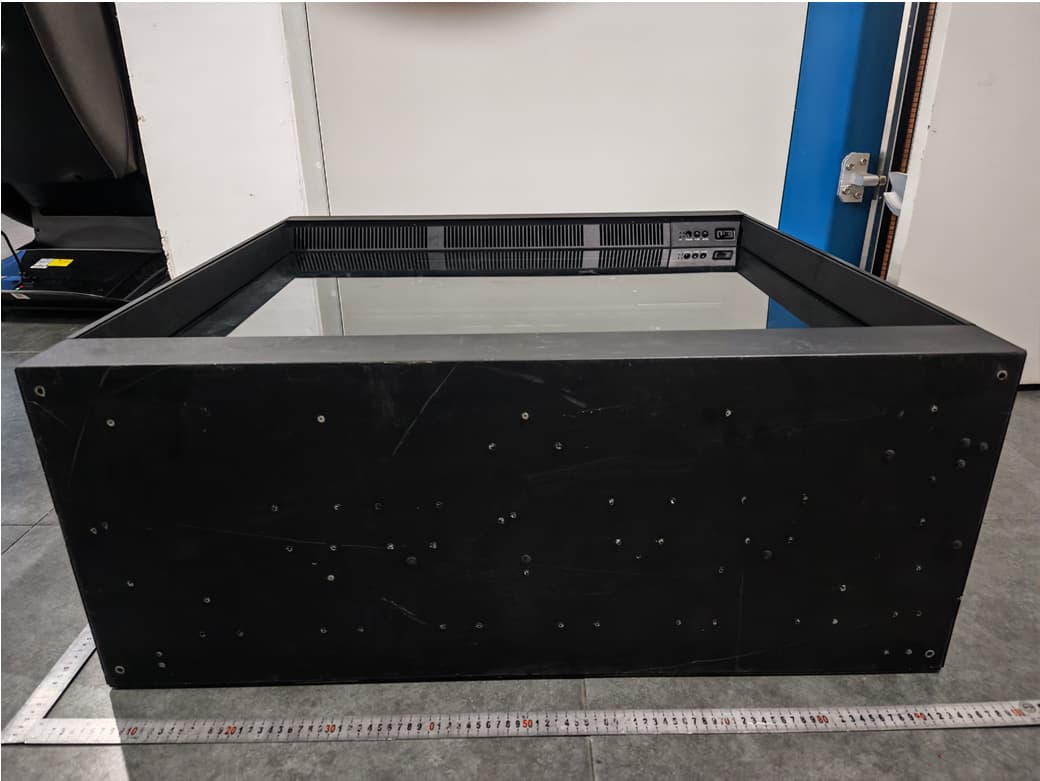
2A2IZ-HE6LE
Apr 30, 2026Electric Fireplace
Equipment Class
DTS - Digital Transmission System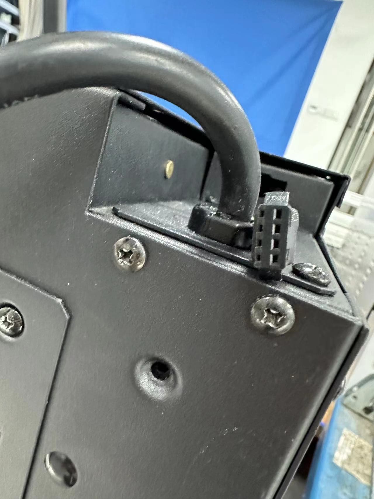
2A2IZ-LEX4-S
Oct 10, 2023Electric Fireplace
Equipment Class
DTS - Digital Transmission System