2A2NY-DDL-M1Intelligent microscope
Beaver technology (Shenzhen) Co. , Ltd.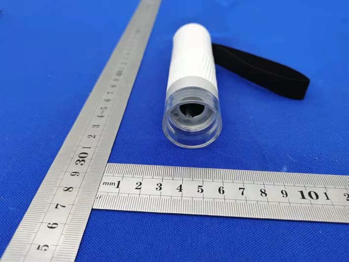
Click to zoom
Application Details
- Equipment Class
- DTS - Digital Transmission System
- Date of Grant
- Jul 23, 2021
- Application Purpose
- Original Equipment
- Date of Application
- Jul 23, 2021
- Equipment Note
- Intelligent microscope
- Frequency Range
- 2412.00000000 - 2462.00000000
- Country
- China
Documents & Files
Document Text
Text extracted from the exhibit documents filed with the FCC. Open a document above to read the original.
Users Manual
DDL-M1IntelligentMicroscope OperatingInstructionV1.0 Contents Notice for Use ............................................................... ............................................................... ....... 3 Product Introduction ............................................................... ............................................................ 4 Microscope Installation Instructions ............................................................... ...... ..................... 4 Microscope Stand Installation Instruction ............................................................... ................... 5 Charging Instruction ............................................................... .................................................... 6 Microscope Monomer Introduction ............................................................... ............................ 7 H ow to Use the Microscope ............................................................... ........................................ 9 Microscope Base Introduction ............................................................... .................................. 11 How to Use the Microscope Base ............................................................... ............................. 13 Accessories and tools ............. ............................................................... ................................... 16 APP Usage Guide ............................................................... .............................................................. 16 How to Use on Android/iOS ............................................................... ..................................... 17 How to Use on PC ......................... ............................................................... ............................ 19 For Windows ............................................................... ..................................................... 19 For MAC ............................................................... ........................................................... 22 Microscope Trouble Shooting ........................ ............................................................... ................... 26 Product Performance failure table ............................................................... ..................................... 28 Storage Environment ............................................................... ......................................................... 29 Operating Environment ........................ ............................................................... ............................. 29 3 Notice for Use Please read this manual carefully and use it correctly.Pay attention to the protection of the lens part,be sure to close the lens co ver after use,to avoid dust or foreign matter. This microscope can be used by hand,or can be inserted into the base as a tabl e.Pay attention to the strength of the insertion to avoid damaging the component s. When placing the specimen,please pay attention to the position,and place it as far as possible in the center of the lens right below.Avoid having a bad experienc e with blurred objects. 4 Product Introduction偕 Microscope Installation Instructions Microscope Structure Microscope monomer Microscope base 5 偖 Microscope Stand Installation Instruction Step 1. Remove the cover of the Step 2. Hand strap facing the rear,the rear microscope monomer lens. slot should be aligned with the mounting hole. Step 3. Holding the base with one hand, Step 4. Insert it to the bottom insert the microscope monomer vertically (focus wheel is all exposed). down into the mounting hole. 6 偗 Charging Instruction The indicator light onmicroscope monomer The indicator light on microscope base When the microscope monomer is lowbattery,the power indicator blue light flashes quickly. The red light is always on whencharging,and the indicator goes off when full. During charging,if there is slight heat in the microscope shell and battery,please rest assured that it is normal Whenthemicroscopebaseislow battery,the power indicator light flashes red. The red light is always on when charging,and the great light is always on when full. You can charge device by your daily phone charger,computer,or power bank. Charging time should not exceed 12h to avoid affecting the battery life. 7 偘 Microscope Monomer Introduction Focus wheel: Counterclockwise rotation: zoom inClockwise rotation: zoom out (Notice:There are two magnifications to rotate the focus wheel at the same distance.Lifting knob on the base and magnification /minification button can also be adjust ed for multiple,when adjusted the focus wheel,lifting knob and magnification /minification b utton together,the maximum magnification is 400 times.) 8 Power button: Long press the button for 3s,and the light on the microscope monomer or the l ight on the microscope base will light up,which means the microscope has been turned o n.Press for 3s again,when the light goes out,means the microscope has been turned off. Power/WiFi connection indicator: When the battery is low,the blue light flashes quickly.When charging,the red light is always on.The blue light is always on when WiFi is successfully connected,and the blue light flashes when WiFi is not connected. 9 偙 How to Use the Microscope Connect the microscope and mobile app via WiFi. Remove the lens cover. Hold the upper part of the microscope with one hand, the tip of the finger can be put into the hand strap to avoid falling. Turn on the microscope by pressing the power button. 10 Align the lens of the microscope at the object to be observed. Rotate the focus wheel with the other hand and observe the display of thephone.At this time,you can adjust the focus wheel to the best viewing ratio. 11 做 Microscope Base Introduction Opening and closing the microscope base Turn the light brightness knob clockwise and hear a “click”,the observati on window will lig…
Text truncated - open the document above for the full version.
Cover Letter(s)
Date: Jul.20.2021 Equipment Autorisation Division Federal Communications Commission 7435 Oakland Mills Road Columbia, MD 21046 FCC ID: 2A2NY-DDL-M1 Product Name: Intelligent microscope Request for Confidentiality Pursuant to Sections 0.457 and 0.459 of the commission’s rules, we hereby request that the following documents be held confidential: (List here the documents for which you are seeking confidentiality – for example ...) • Schematics • Block diagram • Operation description These materials contain trade secrets and proprietary information and are not customarily released to the public. The public disclosure of this information might be harmful to the company and provide unjustified benefits to our competitors. <Signature> Name: Chen/Dino Title: CTO Company: Beaver technology (Shenzhen) Co. , Ltd.
Cover Letter(s)
Date: Jul.20.2021 Federal Communications Commission Authorization & Evaluation Division 7345 Oakland Mills Road Columbia, Maryland 21046 RE: LETTER OF AGENT AUTHORIZATION To Whom It May Concern: We, the undersigned, hereby authorize Compliance Testing, LLC to act on our behalf in all matters relating to application for equipment authorization, including the signing of all documents relating to these matters. We also hereby certify that no party to the application authorized hereunder is subject to the denial of benefits, including FCC benefits, pursuant to Section 5301 of the Anti-Drug Abuse Act of 1988, 21 U.S.C.853(a). Sincerely, <Signature> Name: Chen/Dino Title: CTO Company: Beaver technology (Shenzhen) Co. , Ltd.
Cover Letter(s)
Date:Jul.20.2021 Federal Communications Commission Authorization & Evaluation Division 7345 Oakland Mills Road Columbia, Maryland 21046 Authority to Act as Agent On our behalf, I appoint Shenzhen CTB Testing Technology Co., Ltd. Add: Floor 1&2, Building A, No. 26 of Xinhe Road, Xinqiao Community, Xinqiao Street, Baoan District, Shenzhen, Guangdong, China to act as our agent in the preparation of this application for equipment certification. I certify that submitted documents properly describe the device or system for which equipment certification is sought. I also certify that each unit manufactured, imported or marketed, as defined in the Federal Communications Commission’s regulations will have affixed to it a label identical to that submitted for approval with this application. For instances where our authorized agent signs the application for certification on our behalf, I acknowledge that all responsibility for complying with the terms and conditions for certification, still resides with Beaver technology (Shenzhen) Co. , Ltd. Add: 101, building f6, F518 fashion creative park, labor community, Xixiang Street, Bao 'an district, Shenzhen, China <Signature> Name: Chen/Dino Title: CTO Company: Beaver technology (Shenzhen) Co. , Ltd.
External Photos
External Photos
ID Label/Location Info
Model: DDL-M1 FCC ID:2A2NY-DDL-M1 Label Location
Internal Photos
Internal Photos ANT
RF Exposure Info
Shenzhen CTB Testing Co., Ltd. FCC ID: 2A2NY-DDL-M1 Portable device According to §15.247(e)(i) and §1.1307(b)(1), systems operating under the provisions of this section shall be operated in a manner that ensures that the public is not exposed to radio frequency energy level in excess of the Commission’s guidelines. According to KDB447498 D01 General RF Exposure Guidance V06 The 1-g SAR and 10-g SAR test exclusion thresholds for 100 MHz to 6 GHz at test separation distances ≤ 50 mm are determined by: [(max. power of channel, including tune-up tolerance, mW)/(min. test separation distance, mm)]·[√f(GHZ)] ≤ 3.0 for 1-g SAR and ≤ 7.5 for 10-g extremity SAR, where: • f(GHZ) is the RF channel transmit frequency in GHz • Power and distance are rounded to the nearest mW and mm before calculation • The result is rounded to one decimal place for comparison When the minimum test separation distance is < 5 mm, a distance of 5 mm is applied to determine SAR test exclusion. Wifi: Modulation Channel Freq. (GHz) Conduct ed power (dBm) Conducte d power (mW) Tune-up power (dBm) Max tune-up power (dBm) Max tune-up power (mW) Distance (mm) Result calculatio n SAR Exclusion threshold SAR test exclusion 2.4127.1435.188±19.007.94<52.467283.00YES 2.4377.4485.568±19.007.94<52.480033.00YES 2.4627.3015.378±19.007.94<52.492723.00YES 2.4126.2944.267±18.006.31<51.959833.00YES 2.4376.1494.127±18.006.31<51.969963.00YES 2.4626.1244.107±18.006.31<51.980043.00YES 2.4125.3533.436±17.005.01<51.556753.00YES 2.4375.8643.866±17.005.01<51.564803.00YES 2.4625.3223.416±17.005.01<51.572803.00YES 2.422 3.131 2.064±15.003.16<50.984283.00YES 2.437 3.076 2.034±15.003.16<50.987323.00YES 2.452 3.314 2.144±15.003.16<50.990353.00YES 802.11b 802.11g 802.11n( HT20) 802.11n( HT40) Conclusion: For the max result : 2.50182≤ FCC Limit 3.0 for 1g SAR.
Test Report
Shenzhen CTB Testing Technology Co., Ltd. Report No.: CTB210705001RF Report Tel: 4008-707-283 Web: http://www.ctb-lab.netPage 1 of 70 TEST REPORT Compiled by: Reviewed by: Approved by: Arron Liu Bin Mei Rita Xiao / Director The test report is effective only with both signature and specialized stamp. This result(s) shown in this report refer only to the sample(s) tested. Without written approval of Shenzhen CTB Testing Technology Co., Ltd. this report can’t be reproduced except in full. The tested sample(s) and the sample information are provided by the client. Product Name: Intelligent microscope FCC ID: 2A2NY-DDL-M1 Trademark: 当当狸 Model Number: DDL-M1 Prepared For: Beaver technology (Shenzhen) Co. , Ltd. Address: 101, building f6, F518 fashion creative park, labor community, Xixiang Street, Bao 'an district, Shenzhen, China Manufacturer: Beaver technology (Shenzhen) Co. , Ltd. Address: Changxing Science and Technology Industrial Park, Changzhen community, Yutang Street, Guangming District, Shenzhen, China Prepared By: Shenzhen CTB Testing Technology Co., Ltd. Address: Floor 1&2, Building A, No. 26 of Xinhe Road, Xinqiao Street, Baoan District, Shenzhen China Sample Received Date: Jun. 30, 2021 Sample tested Date: Jun. 30, 2021 to Jul. 7, 2021 Issue Date: Jul. 7, 2021 Report No.: CTB210705001RF Test Standards FCC Part15.247 ANSI C63.10:2013 Test Results PASS Remark: This is WIFI-2.4GHz band radio test report. Shenzhen CTB Testing Technology Co., Ltd. Report No.: CTB210705001RF Report Tel: 4008-707-283 Web: http://www.ctb-lab.net Page 2 of 70 TABLE OF CONTENT Test Report Declaration Page 1. VERSION............................................................ 4 2. TEST SUMMARY ..................................................... 5 3. MEASUREMENT UNCERTAINTY ....................................... 6 4. PRODUCT INFORMATION AND TEST SETUP ........................... 7 4.1 Product Information ..................................................... 7 4.2 Test Setup Configuration ................................................ 7 4.3 Support Equipment ..................................................... 8 4.4 Channel List ........................................................... 9 4.5 Test Mode ............................................................. 9 4.6 Test Environment ....................................................... 9 5. TEST FACILITY AND TEST INSTRUMENT USED ........................ 10 5.1 Test Facility ........................................................... 10 5.2 Test Instrument Used .................................................. 10 6. AC POWER LINE CONDUCTED EMISSION .............................. 12 6.1 Block Diagram Of Test Setup............................................ 12 6.2 Limit ................................................................. 12 6.3 Test procedure ........................................................ 12 6.4 Test Result ........................................................... 14 7. RADIATED SPURIOUS EMISSION ..................................... 16 7.1 Block Diagram Of Test Setup............................................ 16 7.2 Limit ................................................................. 16 7.3 Test procedure ........................................................ 17 7.4 Test Result ........................................................... 18 8. BAND EDGE AND RF COUNDUCTED SPURIOUS EMISSIONS ............ 40 8.1 Block Diagram Of Test Setup............................................ 40 8.2 Limit ................................................................. 40 8.3 Test procedure ........................................................ 40 8.4 Test Result ........................................................... 41 9. COUDUCTED OUTPUT POWER....................................... 49 9.1 Block Diagram Of Test Setup............................................ 49 9.2 Limit ................................................................. 49 9.3 Test procedure ........................................................ 49 9.4 Test Result ........................................................... 50 10. 6DB OCCUPIED BANDWIDTH ........................................ 55 10.1 Block Diagram Of Test Setup .......................................... 55 10.2 Limit ................................................................ 55 10.3 Test procedure ....................................................... 55 10.4 Test Result .......................................................... 55 11. POWER SPECTRAL DENSITY ........................................ 61 11.1 Block Diagram Of Test Setup .......................................... 61 11.2 Limit ................................................................ 61 11.3 Test procedure ....................................................... 61 Shenzhen CTB Testing Technology Co., Ltd. Report No.: CTB210705001RF Report Tel: 4008-707-283 Web: http://www.ctb-lab.net Page 3 of 70 11.4 Test Result .......................................................... 62 12. ANTENNA REQUIREMENT ........................................... 67 13. EUT PHOTOGRAPHS ................................................ 68 14. EUT TEST SETUP PHOTOGRAPHS ................................... 69 (Note: N/A means not applicable) Shenzhen CTB Testing Technology Co., Ltd. Report No.: CTB210705001RF Report Tel: 4008-707-283 Web: http://www.ctb-lab.net Page 4 of 70 1. VERSION Report N o. Issue Date Description Approved CTB210705001RF Jul. 7, 2021 Original Valid Shenzhen CTB Testing Technology Co., Ltd. Report No.: CTB210705001RF Report Tel: 4008-707-283 Web: http://www.ctb-lab.net Page 5 of 70 2. TEST SUMMARY The Product has been tested according to the following specifications: Test Item Test Requirement Test method Result AC Power Line Conducted Emission 47 CFR Part 15 Subpart C Section 15.207 ANSI C63.10-2013 PASS Radiated Spurious emissions 47 CFR Part 15 Subpart C Section 15.205/15.209 ANSI C63.10-2013 PASS Band edge and…
Text truncated - open the document above for the full version.
Test Setup Photos
Radiated Emission Below 1G Above 1G Conducted Emission
Contact Information
Applicant
Dino Chen(CTO)
Test Firm
Shenzhen CTB Testing Technology Co., Ltd.Rita Xiao
[email protected]86-13538218145
Technical Specifications
| # | Rule Parts | Frequency Range | Power Output |
|---|---|---|---|
| 1 | 15C | 2.41 GHz - 2.46 GHz | 5.56 mW |