2A2VJ-EYENOVIAGEN1Optejet Base G1
Eyenovia Inc.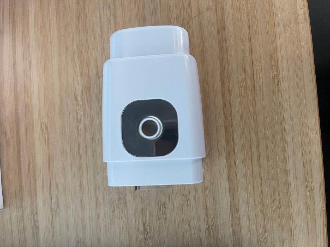
Click to zoom
Application Details
- Equipment Class
- DTS - Digital Transmission System
- Date of Grant
- Oct 04, 2021
- Application Purpose
- Original Equipment
- Date of Application
- Oct 04, 2021
- Equipment Note
- Optejet Base G1
- Frequency Range
- 2402.00000000 - 2480.00000000
- Company
- Eyenovia Inc.
- Country
- United States
Documents & Files
Document Text
Text extracted from the exhibit documents filed with the FCC. Open a document above to read the original.
Users Manual
MydCombi ™ Base Unit Charging Instructions & Safety Manual Charging Instructions & Safety Manual MydCombi™ Base Unit Page 2 of 9 Table of Contents 1. NOTES ON SAFETY: ................................................................................................................................. 3 2. OPERATION: .............................................................................................................................................. 4 3. SPECIFICATIONS: ....................................................................................................5 4. EMC COMPLIANCE: ................................................................................................................................. 6 5. DISPOSAL: ................................................................................................................................................. 8 6. REPORTING TO MANUFACTURER AND AUTHORITIES: ................................................................ 8 7. SYMBOLS USED IN LABELS ON THE MIDD BASE: .......................................................................... 9 Charging Instructions & Safety Manual MydCombi™ Base Unit Page 3 of 9 MydCombi™ Base Unit Charging Instructions 1. NOTES ON SAFETY: WARNING Contains Lithium-Ion Battery MydCombi™ Base Unit contains a Lithium-Ion Battery. Damage to Base Unit can cause fire. Do not puncture Base Unit. Do not expose Base Unit to excessive heat (≥50°C). Check with all governing travel bodies (e.g. The Transportation Security Administration) for current requirements before flying. WARNING Do not use after expiration date Expiration dates are published on the back label for the MydCombi™ Base Unit. Use of Base Units should be discontinued if the expiration date has passed. WARNING Inspect for device damage Do not use if package has been previously opened or damaged. Do not use the MydCombi™ Base Unit if there is evidence of damage. Doing so could result in injury. WARNING Tampering of parts in the MydCombi™ Base Unit Do not tamper with or attempt to open up the parts of the MydCombi™ Base Unit. Doing so could cause damage to the unit and result in personal injury. WARNING Risk of usage Failure to use the MydCombi™ Base Unit in accordance with these instructions could result in complications during dose dispensing. If the MydCombi™ Base Unit has been idling for an extended amount of time, a waste dose shot should be dispensed. The MydCombi™ Base Unit must be kept in the upright position during use. WARNING Risk due to insufficient user training Training is required prior to use of the MydCombi™ Base Unit. The user should be adequately trained in handling the MydCombi™ Base Unit prior to use. The MydCombi™ Cartridge is designed to solely interface with the MydCombi™ Base Unit. Refer to the MydCombi™ Cartridge instructions for use. WARNING Risk due to battery leakage If there is any sign of battery leakage, do not use the MydCombi™ Base Unit WARNING Keep Dry The MydCombi™ Base Unit should not be exposed to water and should be kept dry. WARNING Transportation and Storage Do not store or transport the MydCombi™ Base Unit where it can encounter sharp or metallic objects. WARNING Risk of electrical leakage Non-hazardous voltage is present during normal use. WARNING Do not use with other equipment Use of this equipment adjacent to or stacked with other equipment should be avoided because it could result in improper operation. If such use is necessary, this equipment and the other equipment should be observed to verify that they are operating normally. WARNING Do not use with non-certified USB Charger Device is intended to be recharged using MicroUSB cable (not included). Use of USB charger other than those specified or provided in the recommended USB Charger list could result in increased electromagnetic emissions or decreased electromagnetic immunity of this equipment and result in improper operation. CAUTION For professional use Federal law restricts this device to sale by or on the order of a physician (21 CFR §801.109(b)(1)). CAUTION Radiation Emission This equipment emits radiation. Charging Instructions & Safety Manual MydCombi™ Base Unit Page 4 of 9 2. OPERATION: NOTE: If the packaging is opened or damaged, do not use the contents. Instead, contact Eyenovia at [email protected] HOW TO STORE the MydCombi™ Base Unit Store in a secure location at room temperature 59-85°F (15-30°C) away from direct sunlight and excessive heat. - Do not heat or freeze the MydCombi™ Base Unit - Do not get the MydCombi™ Base Unit wet or expose to fluids. - Do not tamper with or attempt to open the parts of the MydCombi™ Base Unit. The MydCombi™ Base Unit contains a lithium ion battery 1 . CHARGING the MydCombi™ Base Unit Before beginning: 1. If packaging is opened or damaged, do not use the contents. Instead, get a new package. 2. A USB Cable is required to charge the MydCombi™ Base Unit. - The cable can be connected either to a wall outlet plug or to a USB port. 3. The MydCombi™ Base Unit must be charged before first use. - Charging may be performed either before or after cartridge assembly attachment. Perform these steps to charge Optejet base: 1. Push USB cable into charging port. 2. Connect opposite end of USB cable to wall outlet plug or USB port. - Battery light BLINKS GREEN while charging. 3. Charge until battery light turns SOLID GREEN and remove charging cable from base. Note: Excessive charging may decrease the battery life. Weekly charging or charging once the LED light starts blinking red (signaling a low battery), is preferable. MydCombi™ Base Unit BATTERY INDICATORS If you see... It means... Mirror Light AND Battery Light SOLID BLUE Ready to dose Battery Light BLINKING GREEN Battery is charging Battery Light SOLID GREEN Battery is fully charged Battery Light BLINKING RED Battery is low Battery Light SOLID RED Charge MydCombi™ Base Unit Mirror Light AND Battery Light BLINKING BLUE Warning for automatic medicine dis…
Text truncated - open the document above for the full version.
Cover Letter(s)
1(1) 09/08/2021 Attention: Application Examiner RE: Request for Confidentiality Applicant: Eyenovia FCC ID: 2A2VJ-EYENOVIAGEN1 To Whom It May Concern: Permanent Confidentiality Request is hereby submitted by Eyenovia, Inc. to withhold permanently from public review certain portions of the application for equipment certification for the referenced FCC identifiers. This request for confidentiality is made pursuant to 47 CFR 0.457(d) and 0.459 of the FCC Rules. In particular, the following sections of the application are to be kept permanently confidential: •Schematics •Detailed Block Diagrams Rationale for request for confidentiality: Eyenovia, Inc. has invested considerable time and materials in research and development to produce the referenced product. Disclosure of the permanently confidential portions of this application to competitors would not only give them significant competitive advantages in developing similar products, but would also disclose successful implementation of unpublished, leading edge technology developed by us. The fee for confidentiality has been submitted along with the fee for certification. If you have questions or need further information, please contact the undersigned. Sincerely, Kris Rodgers Senior Buyer Eyenovia, Inc.
External Photos
External Photos:
ID Label/Location Info
LS-17076 Rev. A MydCombi Base Label Optejet Label Placement on Base: 1.00” Scale – 1:1 1.00” Scale – 2:1 Reference Line (Do Not Print) FCC ID: 2A2VJ-EYENOVIAGEN1 FCC ID: 2A2VJ-EYENOVIAGEN1
Internal Photos
Internal Photos:
Operational Description
SUMMARY: This document contains the operational description for the Bluetooth radio design implemented by Eyenovia, Inc. The guide specifically references the design for the nRF51x22 radio module. OPERATIONAL DESCRIPTION: The nRF51 series devices employ Nordic Semiconductor's 3rd generation 2.4 GHz radio architecture. This radio uses narrow-band GFSK modulation and is frequency adaptable across the 2.4 GHz ISM band. A 2450AT18B100E surface mount 2.4Ghz, 0.5dBi chip antenna, paired with a 2450BM14E0003T 2.45 GHz Impedance Matched Balun-Filter, provides and receives signal to the Nordic nRF51x22 MCU. Programmable gain control, modulation, and byte synchronization are performed digitally. The nRF51 series ultra-low power 2.4 GHz GFSK RF transceiver is designed and optimized to operate in the worldwide ISM frequency band at 2.400 GHz to 2.4835 GHz. Configurable radio modulation modes and packet structure makes the transceiver interoperable with Bluetooth low energy (BLE) (Bluetooth 4.2), ANT™, Gazell, Enhanced Shockburst™, and a range of other 2.4 GHz protocol implementations. The RADIO implements EasyDMA (Direct Memory Access) for reading and writing of data packets from and to the RAM without CPU involvement. The radio implements a mechanism for measuring the power in the received radio signal. This feature is called Received Signal Strength Indicator (RSSI). The final radio frequency amplifying devices for normal operation over the provided power range is comprised of the Nordic nRFF51x22 MCU which is powered by 3V LDO from a single cell 3.7V Li-Po battery. The radio current consumption DC-DC at 3V for TX at +4dBm output power is 10.5mA, for TX at 0dBm output power is 8.06mA, and for RX at 1Mbs is 9.7mA. For operation of the Nordic nRF chip, an external 16MHz 8pF crystal oscillator and external 32.768 kHz 12.5pF crystal oscillator were utilized to support the clock control and overall function. Transceiver consists of a small matching network that is used for impedance matching with the antenna and suppress the spurious radiation. Custom PCB is enclosed in device subshell and is inaccessible to user.
RF Exposure Info
Eyenovia, Inc. RF Exposure Exhibit SCOPE OF WORK EMC TESTING – Optejet® Dispenser Model: Microdose Dispenser 1.0 REPORT NUMBER 104729499MPK-008 ISSUE DATE September 08, 2021 REVISED DATE N/A PAGES 8 DOCUMENT CONTROL NUMBER Non-Specific Radio Report Shell Rev. December 2017 MPK © 2017 INTERTEK Non-Specific Radio Report Shell Rev. December 2017 MPK EMC Report for Eyenovia, Inc. on the Optejet® Dispenser Page 2 of 8 RF Exposure Exhibit (Portable devices) Report Number: 104729499MPK-008 Project Number: G104729499 Report Issue Date: September 08, 2021 Product Designation: Model Tested: Optejet® Dispenser Microdose Dispenser 1.0 FCC ID: 2A2VJ-EYENOVIAGEN1 to 47CFR 2.1093 RSS-102 Issue 5 for Eyenovia, Inc. Tested by: Client: Intertek 1365 Adams Court Menlo Park, CA 94025 USA Eyenovia, Inc. 8748 Technology Way Reno, NV 89521 USA Report prepared by: Report reviewed by: Aaron Chang / Senior Project Engineer Krishna Vemuri / EMC Manager This report is for the exclusive use of Intertek's Client and is provided pursuant to the agreement between Intertek and its Client. Intertek's responsibility and liability are li mited to the terms and conditions of the agreement. Intertek assumes no liability to any party, other than to the Client in accordance with the agreement, for any loss, expense or damage occasioned by the use of this report. Only the Client is authorized to permit copying or distribution of this report and then only in its entirety. Any use of the Intertek name or one of its marks for the sale or advertisement of the tested material, product or service must first be approved in writing by Intertek. The observations and test results in this report are relevant only to the sample tested. This report by itself does not imply that the material, product, or service is or has ever been under an Intertek certification program. REPORT NUMBER: 104729499MPK-008 Issued: September 08, 2021 Non-Specific Radio Report Shell Rev. December 2017 MPK EMC Report for Eyenovia, Inc. on the Optejet® Dispenser Page 3 of 8 Report No. 104729499MPK-008 Equipment Under Test: Optejet® Dispenser Trade Name: Eyenovia, Inc. Model(s) Tested: Microdose Dispenser 1.0 Applicant: Eyenovia, Inc. Contact: Kris Rodgers Address: Eyenovia, Inc. 8748 Technology Way Reno, NV 89521 Country: USA Email: [email protected] Applicable Regulation: 47CFR 2.1093 RSS-102 Issue 5 REPORT NUMBER: 104729499MPK-008 Issued: September 08, 2021 Non-Specific Radio Report Shell Rev. December 2017 MPK EMC Report for Eyenovia, Inc. on the Optejet® Dispenser Page 4 of 8 TABLE OF CONTENTS 1.0 RF Exposure Summary ................................................................................................................... 5 2.0 RF Exposure Limits ........................................................................................................................ 5 3.0 Test Results (Portable Configuration) .......................................................................................... 6 4.0 Document History ........................................................................................................................... 8 REPORT NUMBER: 104729499MPK-008 Issued: September 08, 2021 Non-Specific Radio Report Shell Rev. December 2017 MPK EMC Report for Eyenovia, Inc. on the Optejet® Dispenser Page 5 of 8 1.0 RF Exposure Summary Test Reference FCC Reference Industry Canada Result Radio frequency Radiation Exposure Evaluation 47 CFR§2.1093 RSS-102 Issue 5 Complies 2.0 RF Exposure Limits 2.1 FCC Limits According to FCC KDB 447498 D01 v06 Appendix A, at frequency 2450 MHz and separation distance of ≤ 5 mm SAR Exemption limit is ≤ 10 mW. Note: 10-g Extremity SAR Test Exclusion Power Thresholds are 2.5 times higher than the 1-g SAR Test Exclusion Thresholds indicated above. 2.2 Industry Canada Limits According to RSS-102 sec. 2.5.1 table 1, at frequency 2450 MHz and separation distance of ≤ 5 mm SAR Exemption limit is ≤ 4 mW. Note: For limb-worn devices where the 10-gram value applies, the exemption limits for routine evaluation in Table 1 of RSS-102 are multiplied by a factor of 2.5. REPORT NUMBER: 104729499MPK-008 Issued: September 08, 2021 Non-Specific Radio Report Shell Rev. December 2017 MPK EMC Report for Eyenovia, Inc. on the Optejet® Dispenser Page 6 of 8 3.0 Test Results (Portable Configuration) 3.1 Classification For purposes of this section, a portable device is defined as a transmitting device designed to be used so that the radiating structure(s) of the device is/are within 20 centimeters of the body of the user. Per the applicant, Optejet® Dispenser is not intended to be worn on the body. 3.2 EIRP calculations The Optejet® Dispenser consists of Bluetooth Low Energy radio. 3.3 Maximum RF Power Fr equency Range (MHz) RF Output (dBm) Antenna Gain 1 (dBi) Note 2402-2480 -1.03 0.5 Conducted power measurements were taken from Report # 104729499MPK-007. 1 As declared by the manufacturer. REPORT NUMBER: 104729499MPK-008 Issued: September 08, 2021 Non-Specific Radio Report Shell Rev. December 2017 MPK EMC Report for Eyenovia, Inc. on the Optejet® Dispenser Page 7 of 8 3.4 RF Exposure Calculation for Optejet® Dispenser 3.4.1 RF Exposure calculation for FCC KDB 447498 D01 v06 According to FCC KDB 447498 D01 v06 Appendix A, at frequency 2450 MHz and separation distance of ≤ 5 mm SAR Exemption limit is ≤ 10 mW. Max Peak Conducted Power measured = -1.03 dBm or 0.789 mW No duty cycle was considered. Therefore, the Maximum EIRP calculated is -1.03 dBm (RF Conducted Power) + 0.5 dBi (Antenna Gain) = -0.53 dBm or 0.885 mW. Results: SAR evaluation is not required since the higher of the maximum conducted or equivalent isotopically radiated power (EIRP) source-based, time averaged output power is below the exemption limit. Note: Antenna gains below 0 are considered as 0dBi. 3.4.2 RF Exposure calculation for RSS-102 Issue 5 According to RSS-102 sec. 2.5.1, at frequency 2450 MHz and separation distance of ≤ 5 mm SAR Exemption limit is ≤ 4 mW. M…
Text truncated - open the document above for the full version.
Test Report
EMC Report for Eyenovia, Inc. on the Optejet® Dispenser File: 104729499MPK-007 Page 1 of 66 TEST REPORT Report Number: 104729499MPK-007 Project Number: G104729499 Report Issue Date: September 08, 2021 Testing performed on Optejet® Dispenser Model Number: Microdose Dispenser 1.0 FCC ID: 2A2VJ-EYENOVIAGEN1 to FCC Part 15 Subpar t C (15.247) ISED RSS-247 Issue 2 For Eyenovia, Inc. Test Performed by: Test Authorized by: Intertek 1365 Adams Court Menlo Park, CA 94025 USA Eyenovia, Inc. 8748 Technology Way Reno, NV 89521 USA Prepared by: Date: September 08, 2021 Aaron Chang Reviewed by: Date: September 08, 2021 Krishna K Vemuri This report is for the exclusive use of Intertek's Client and is provided pursuant to the agreement between Intertek and its Cli ent. Intertek's responsibility and liability are limited to the terms and conditions of the agreement. Intertek assumes no liability to any party, other than to the Client in accordance with the agreement, for any loss, expense or damage occasioned by the use of this report. Only the Client is authorized to copy or distribute this report and then only in its entirety. Any use of the Intertek name or one of its marks for the sale or advertisement of the tested material, product or service must first be approved in writing by Inter tek. The observations and test results in this report are relevant only to the sample tested. This report by itself does not imply that the material, product, or service is or has ever been under an Intertek certification program. This report must not be used to claim product endorsement by A2LA, NI ST nor any other agency of the U.S. Government. EMC Report for Eyenovia, Inc. on the Optejet® Dispenser File: 104729499MPK-007 Page 2 of 66 Report No. 104729499MPK-007 Equipment Under Test: Optejet® Dispenser Model Number: Microdose Dispenser 1.0 Applicant: Eyenovia, Inc. Contact: Kris Rodgers Address: Eyenovia, Inc. 8748 Technology Way Reno, NV 89521 Country: USA Email: [email protected] Applicable Regulation: FCC Part 15 Subpart C (15.247) ISED RSS-247 Issue 2 Date of Test: July 26, 2021 to July 28, 2021 & September 1-8, 2021 We attest to the accuracy of this report: Aaron Chang Senior Project Engineer Krishna K Vemuri EMC Manager EMC Report for Eyenovia, Inc. on the Optejet® Dispenser File: 104729499MPK-007 Page 3 of 66 TABLE OF CONTENTS 1.0 Summary of Tests ................................................................................................................. 4 2.0 General Information ............................................................................................................. 5 2.1 Product Description ............................................................................................................ 5 2.2 Related Submittal(s) Grants ................................................................................................ 6 2.3 Test Facility ......................................................................................................................... 6 2.4 Test Methodology ............................................................................................................... 6 2.5 Measurement Uncertainty ................................................................................................. 6 3.0 System Test Configuration ..................................................................................................... 7 3.1 Support Equipment ............................................................................................................. 7 3.2 Block Diagram of Test Setup ............................................................................................... 7 3.3 Justification ......................................................................................................................... 9 3.4 Software Exercise Program ................................................................................................. 9 3.5 Mode of Operation during Test .......................................................................................... 9 3.6 Modifications Required for Compliance ............................................................................. 9 3.7 Additions, Deviations and Exclusions from Standards ........................................................ 9 4.0 Measurement Results .......................................................................................................... 10 4.1 6-dB Bandwidth and 99% Occupied Bandwidth ............................................................... 10 4.2 Maximum Peak Conducted Output Power at Antenna Terminals ................................... 18 4.3 Maximum Power Spectral Density .................................................................................... 22 4.4 Out of Band Antenna Conducted Emission....................................................................... 26 4.5 Transmitter Radiated Emissions ....................................................................................... 30 4.6 AC Line Conducted Emission ............................................................................................. 61 5.0 List of Test Equipment .......................................................................................................... 65 6.0 Document History ................................................................................................................ 66 EMC Report for Eyenovia, Inc. on the Optejet® Dispenser File: 104729499MPK-007 Page 4 of 66 1.0 Summary of Tests Test Reference FCC Reference Industry Canada Result RF Output Power 15.247(b)(3) RSS-247, 5.4.d) Complies 6 dB Bandwidth 15.247(a)(2) RSS-247, 5.2.a) Complies Power Density 15.247(e) RSS-247, 5.2.b) Complies Out of Band Antenna Conducted Emission 15.247(d) RSS-247, 5.5 Complies Transmitter Radiated Emissions 15.247(d), 15.209, 15.205 RSS-247, 5.5 Complies AC Line Conducted Emission 15.207 RSS-GEN Complies Antenna Requirement 15.203 RSS-GEN…
Text truncated - open the document above for the full version.
Contact Information
Applicant
Kris Rodgers
Test Firm
IntertekTesting Services NA Inc.Charles Parker
Technical Specifications
| # | Rule Parts | Frequency Range | Power Output |
|---|---|---|---|
| 1 | 15C | 2.40 GHz - 2.48 GHz | 789.00 µW |