2A2YD1H4468RHFWireless Door Sensor
Refrigerated Transport Electronics, Inc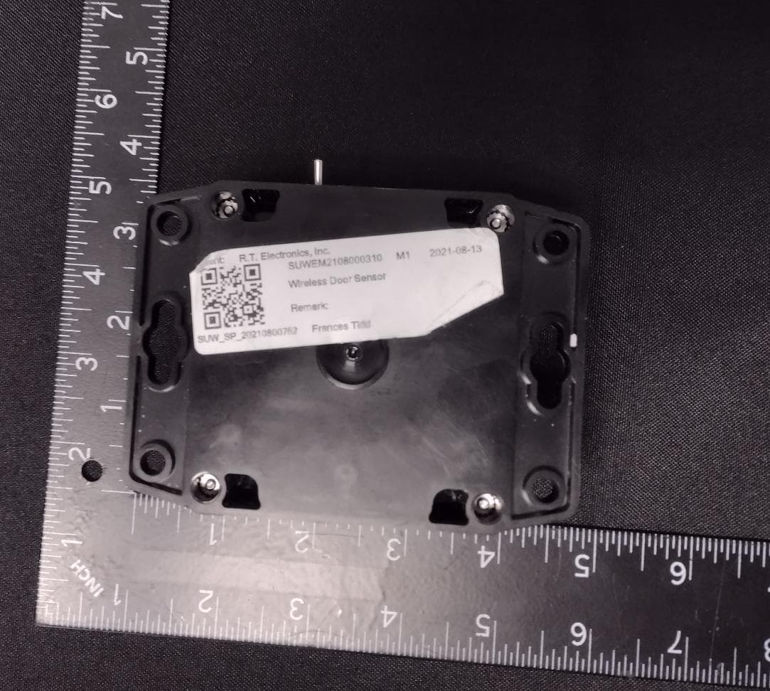
Click to zoom
Application Details
- Equipment Class
- DSC - Part 15 Security/Remote Control Transmitter
- Date of Grant
- Nov 21, 2022
- Application Purpose
- Original Equipment
- Date of Application
- Nov 21, 2022
- Equipment Note
- Wireless Door Sensor
- Frequency Range
- 433.05000000 - 433.05000000
- Country
- United States
Documents & Files
Document Text
Text extracted from the exhibit documents filed with the FCC. Open a document above to read the original.
Users Manual
No.: 98-02747-00 Rev: A Authorization #: ECN1154650 Title: Telematics Device – Door sensor Installation Instructions Supersedes: Page: 1 of 6 Used On: Carrier Lynx Fleet Telematics Device equipped container units Prepared By: P.Vang Approved By: P.Hoover Date: 31May2022 ALL USES AND PUBLICATION RIGHTS RESERVED - PROPERTY OF CARRIER TRANSICOLD, SYRACUSE, NY This document contains technical data the export of which is restricted by the EAR, diversion contrary to U.S. law is prohibited. Proper authorization is required prior to providing this technical data to any other company, entity, person, or destination. U.S. Export Control Classification: EAR99 Instructions for Installing Door sensor Tools Required: 1) Standard hand tools 2) Clean cloth 3) Scotch tape 4) Marker 5) Hot air Gun This instruction should be read through completely before proceeding. Procedure: DOOR SENSOR PAIRING NOTE: • Telematics device and door sensor are paired and must be installed together. Ensure that the door sensor is installed in the same container as the reefer which it was stored. Door Sensor App Instructions Note – The Carrier Door Sensor App is only compatible with Android operating system. 1. Download and install the Carrier Door Sensor App from Google Play Store 2. Once Installed, open the Carrier Door Sensor App 3. To read the current container ID: Ensure NFC (near field communication) is active (refer to your phone Connection/sharing settings). Tap the phone’s NFC to the area shown in Figure 2. No.: 98-02747-00 Rev: A Authorization #: ECN1154650 Title: Telematics Device – Door sensor Installation Instructions Supersedes: Page: 2 of 6 Used On: Carrier Lynx Fleet Telematics Device equipped container units Prepared By: P.Vang Approved By: P.Hoover Date: 31May2022 ALL USES AND PUBLICATION RIGHTS RESERVED - PROPERTY OF CARRIER TRANSICOLD, SYRACUSE, NY 4. The current container ID, if any, will appear at the top. If no container ID is present dashes will be displayed. Figure 4 5. To change or set a new ID before installation: a. Enter the new ID in the “New Reefer ID” field (format XXXX1234567). b. Press set ID button (Figure 5). c. Tap the phone to the NFC area to get confirmation. 6. If the app is not responding when trying to connect to door sensor, restart app and try again. 7. After setting the ID, tap the NFC area again to read the ID and confirm it was set. The new container ID will appear in the top field as in figure 6. Figure 2 Figure 3 Figure 1 Figure 4 Figure 5 Figure 6 XXXX1234567 XXXX1234567 No.: 98-02747-00 Rev: A Authorization #: ECN1154650 Title: Telematics Device – Door sensor Installation Instructions Supersedes: Page: 3 of 6 Used On: Carrier Lynx Fleet Telematics Device equipped container units Prepared By: P.Vang Approved By: P.Hoover Date: 31May2022 ALL USES AND PUBLICATION RIGHTS RESERVED - PROPERTY OF CARRIER TRANSICOLD, SYRACUSE, NY DOOR SENSOR INSTALLATION 1. Collect the door sensor and magnet from the control box storage location. 2. Clean and dry area where sensor and magnet are to be located using a locally approved IPA (Isopropyl Alcohol cleaner) and mark the center position of the door sensor as follows: Magnet Door sensor No.: 98-02747-00 Rev: A Authorization #: ECN1154650 Title: Telematics Device – Door sensor Installation Instructions Supersedes: Page: 4 of 6 Used On: Carrier Lynx Fleet Telematics Device equipped container units Prepared By: P.Vang Approved By: P.Hoover Date: 31May2022 ALL USES AND PUBLICATION RIGHTS RESERVED - PROPERTY OF CARRIER TRANSICOLD, SYRACUSE, NY Between first and second corrugation from right to left, or in case flat panel measure ~11 inches (~28 cm) from door edge as high as possible without overlapping the PVC/rubber rim. Some container models might have a PVC profile on the door edge – do not remove/cut or overlap this. Place the sensor immediately below the profile as shown in figure 7/8. 3. Close right hand side door and leave left hand side door open. 4. Remove red protective backing from the door sensor; ensure the label arrow is facing upwards on the door sensor. Align arrow to the mark on the door and press sensor firmly (around 30 lb.) onto dry marked location for at least 5 seconds. Ambient and surface temperature of door and door sensor to be above 50°F (10°C) for better adhesion. For colder ambient temperature below 50°F (10°C) recommended use of hot air gun. Surface temperature should not exceed 122°F (50°C). Always place the door sensor at the top edge to assure the distance between the sensor and the magnet is no more than 2 inches (5.1 cm). 5. Magnet location: With the container right door closed and using the arrow on the door sensor label as a guidance mark the position on the door header (top rail) for positioning of the magnet. Use this line as a reference to place the magnet as per below: Figure 7 Distance between door sensor and magnet cannot be greater than 2.0” ( 5.1 cm) Figure 8 No.: 98-02747-00 Rev: A Authorization #: ECN1154650 Title: Telematics Device – Door sensor Installation Instructions Supersedes: Page: 5 of 6 Used On: Carrier Lynx Fleet Telematics Device equipped container units Prepared By: P.Vang Approved By: P.Hoover Date: 31May2022 ALL USES AND PUBLICATION RIGHTS RESERVED - PROPERTY OF CARRIER TRANSICOLD, SYRACUSE, NY 6. Remove red protective backing from the magnet. Ensure area has been cleaned in step 1 using the IPA. 7. Position the magnet on the door sill, with the mark on door sill (step 5), aligned horizontally with arrow on door sensor label so that its center is above the center of the door sensor. 8. Press magnet firmly (around 30 lb.) for at least 5 seconds 9. Apply silicone caulking or approved mastic carefully around perimeter of sensor and magnet. 10. After installation and pairing, open and close the door to generate initial events. Check this using Carrier Door Sensor App. a. Last event event time is correct b. Appropriate battery voltage. Should be between 3.4V and 3.6V. If battey voltage low repl…
Text truncated - open the document above for the full version.
Cover Letter(s)
Company Letterhead To: SGS North America Inc. 620 Old Peachtree Road SUITE 100 Suwanee, Georgia United States From: R.T.E. Inc. 1 West Center Street McGraw, NY 13101 United States Regarding: Confidentiality Request regarding application for FCC ID 2A2YD1H4468RHF L ONG TERM CONFIDENTIALITY Pursuant to 47 CFR Section 0.459 and 0.457 of the commission’s rules, the applicant hereby request confidential treatment of the documents listed below, associated with the certification application referenced above. Schematic B lock Diagrams Operational Descriptions T he documents above contain proprietary information not released to the public. Public disclosure of this information may prove harmful to the business of the applicant. SHORT TERM CONFIDENTIALITY Additionally, the applicant requests the following documents be held confidential until the device is marketed or 180 days from the grant date, whichever is less. If the device is marketed within 180 days of the Grant Date, the applicant will notify the TCB per FCC KDB 726920 D01 Confidentiality Request Procedures. External Photos I nternal Photos Test Setup Photos User manual(s) S incerely, Ryan Weeks M anager – Technical Services Refrigerated Transport Electronics, Inc.
Cover Letter(s)
Refrigerated Transport Electronics, Inc. 1 West Center Street McGraw, NY 13101 TO: Federal Communication Commission Date: 10/06/2022 Equipment Authorization Branch 7435 Oakland Mills Road Columbia, MID 21046 Regarding: 2A2YD1H4468RHF To whom it may concern: We, the undersigned, hereby authorize SGS to act on our behalf in all manners relating to application for equipment authorization with respect to the FCC ID above, including signing of all documents relating to these matters. Any and all acts carried out by the agent on our behalf shall have the same effect as acts of our own. We, the undersigned, hereby certify that we are not subject to a denial of federal benefits, that includes FCC benefits, pursuant to Section 5301 of the Anti-Drug Abuse Act of 1988, 21 U.S.C. 853(a). Where our agent signs the application for certification on our behalf, I acknowledge that all responsibility for complying with the terms and conditions for Certification, as specified by SGS North America, Inc., still resides with Refrigerated Transport Electronics (RTE). This authorization is valid until further written notice from the applicant. Name (Printed): Ryan Weeks Title: Manager – Technical Services Signature: On behalf of Company: Refrigerated Transport Electronics, Inc (RTE) Telephone: 1 (607) 836-1121
Cover Letter(s)
09/27/2022 Ryan Weeks Technical Support Manager
External Photos
EXTERNAL PHOTOS FCC ID: 2A2YD1H4468RHF 2 © SGS SA 2016 ALL RIGHTS RESERVED TOP VIEW 3 © SGS SA 2016 ALL RIGHTS RESERVED BACK VIEW 4 © SGS SA 2016 ALL RIGHTS RESERVED SIDE VIEW WWW.SGS.COM
Internal Photos
INTERNAL PHOTOS FCC ID: 2A2YD1H4468RHF 2 © SGS SA 2016 ALL RIGHTS RESERVED PCB -TOPVIEW 3 © SGS SA 2016 ALL RIGHTS RESERVED PCB–BATTERY COMPARTMENT 4 © SGS SA 2016 ALL RIGHTS RESERVED PCB–BOTTOMVIEW 5 © SGS SA 2016 ALL RIGHTS RESERVED RADIOMODULE–TOPVIEWCLOSE-UP 6 © SGS SA 2016 ALL RIGHTS RESERVED RADIOMODULE–LIDREMOVED 7 © SGS SA 2016 ALL RIGHTS RESERVED RADIO MODULE –BOTTOM VIEW WWW.SGS.COM
Test Report
Test Report Number: 4967994EMC02 Rev: 1 Refrigerated Transport Electronics, Inc. / Wireless Door Sensor Page: 1 of 25 Remarks: This document is issued by the Company subject to its General Conditions of Service printed overleaf, available on request or accessible at http://www.sgs.com//en/Terms-and-Conditions.aspx. And for electronic format documents, subject to Terms and Conditions for Electronic Documents at http://www.sgs.com/en/Terms-and-Conditions/terms-e-document.aspx. Attention is drawn to the limitation of liability, indemnification and jurisdiction issues defined therein. Any holder of this document is advised that information contained hereon reflects the Company’s findings at the time of its intervention only and within the limits of Client’s instructions, if any. The Company’s sole responsibility is to its Client and this document does not exonerate parties to a transaction from exercising all their rights and obligations under the transaction documents. This document cannot be reproduced except in full, without prior written approval of the Company. Any unauthorized alteration, forgery or falsification of the content or appearance of this document is unlawful and offenders may be prosecuted to the fullest extent of the law. Unless otherwise stated the results shown in this test report refer only to the sample(s) tested and such sample(s) are retained for a maximum of 30 days only. EMC Test Report Project Number: 4967994 Proposal Number: SUW-202209003414 Report Number: 4967994EMC02 Revision Level: 1 Client: Refrigerated Transport Electronics, Inc. Equipment Under Test: Remote for Wireless Door Sensor Model Name: Wireless Door Sensor Model Number: 1H4468RHF FCC ID: 2A2YD1H4468RHF Applicable Standards: §15.231 Periodic Operation in the band 40.66-40.77MHz and above 70MHz ANSI C63.10:2013 Report issued on: 18 October 2022 Test Result: Compliant FOR THE SCOPE OF ACCREDITATION UNDER CERTIFICATE NUMBER: 3212.01 Report must not be used by the client to claim product certification, approval, or endorsement by A2LA, NIST, or any agency of the Federal Government. Prepared by: Brandon Osborn, Project Engineer Reviewed by: Shawn McGuinness, EMC Engineering Leader Test Report Number: 4967994EMC02 Rev: 1 Refrigerated Transport Electronics, Inc. / Wireless Door Sensor Page: 2 of 25 SGS North America Inc. Consumer and Retail 620 Old Peachtree Road NW, Suite 100, Suwanee, GA 30024 t (770) 570-1800 www.sgs.com Member of the SGS Group (SGS SA) Table of Contents 1 SUMMARY OF TEST RESULTS ..................................................................................................................................... 3 1.1 MODIFICATIONS REQUIRED FOR COMPLIANCE .............................................................................................................. 3 2 GENERAL INFORMATION ............................................................................................................................................. 4 2.1 CLIENT INFORMATION ................................................................................................................................................... 4 2.2 TEST LABORATORY ....................................................................................................................................................... 4 2.3 GENERAL INFORMATION OF EUT .................................................................................................................................. 4 2.4 RATINGS AND DECLARATIONS ....................................................................................................................................... 4 2.5 OPERATING MODES AND CONDITIONS .......................................................................................................................... 5 2.6 EUT CONNECTION BLOCK DIAGRAM ............................................................................................................................ 5 2.7 SYSTEM CONFIGURATIONS ............................................................................................................................................ 5 2.8 SUPPORT EQUIPMENT .................................................................................................................................................... 5 3 INTENTIONAL RADIATOR ANTENNA REQUIREMENT ........................................................................................ 6 3.1 RESULT.......................................................................................................................................................................... 6 3.2 REQUIREMENT ............................................................................................................................................................... 6 3.3 CONCLUSION ................................................................................................................................................................. 6 4 FIELD STRENGTH OF FUNDAMENTAL ..................................................................................................................... 7 4.1 TEST RESULT ................................................................................................................................................................. 7 4.2 TEST METHOD ............................................................................................................................................................... 7 4.3 TEST SETUP DIAGRAM................................................................................................................................................... 8 4.4 TEST SITE ...................................................................................................................................................................... 8 4.5 TEST EQUIPMENT ........................................................................................................................…
Text truncated - open the document above for the full version.
Test Setup Photos
TEST SETUP PHOTOGRAPHS Applicant: Refrigerated Transport Electronics, Inc. Model –1H4468RHF FCC ID: 2A2YD1H4468RHF 2 30-1000 MHZ -FRONT VIEW 3 30-1000 MHZ –REAR VIEW 4 1-4.4 GHZ –FRONT VIEW 5 1-4.4 GHZ –REAR VIEW WWW.SGS.COM © SGS Group Management SA – 2016 – All rights reserved - SGS is a registered trademark of SGS Group Management SA
Contact Information
Applicant
Ryan Weeks
Technical Contact
SGS North America, Inc.Brandon Osborn
[email protected]7705701800
620 Old Peachtree Road NW · Suwanee, Georgia · United States
Non-Technical Contact
SGS North America, Inc.Brandon Osborn
[email protected]7705701800
Test Firm
SGS North America, Inc.David Schramm
Technical Specifications
| # | Rule Parts | Frequency Range | Power Output |
|---|---|---|---|
| 1 | 15.231 | 433.05 MHz - 433.05 MHz | - |