2A377-669Remote Controller
JIANGMEN KEYE ELECTRIC APPLIANCES MANUFACTURING CO., LTD.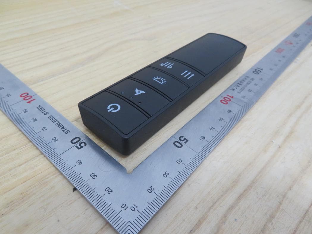
Click to zoom
Application Details
- Equipment Class
- DSC - Part 15 Security/Remote Control Transmitter
- Date of Grant
- Feb 19, 2022
- Application Purpose
- Original Equipment
- Date of Application
- Feb 19, 2022
- Equipment Note
- Remote Controller
- Frequency Range
- 433.92000000 - 433.92000000
- Country
- China
Documents & Files
Document Text
Text extracted from the exhibit documents filed with the FCC. Open a document above to read the original.
Users Manual
THANK YOU USE AND CARE GUIDE 22 IN. LED INDOOR/COVERED OUTDOOR CEILING FAN WITH REMOTE CONTROL 120V 60Hz 0.61A Weight of the fan with light kit: approx. 20.86lbs Questions, problems, missing parts? Before returning to the store, call Home Decorators Collection Customer Service 8 a.m. - 7 p .m., EST, Monday - Friday, 9 a.m.- 6 p .m., EST, Saturday 1-800-986-3460 HOMEDEPOT.COM/HOMEDECORATORS Item #1005818915, 1005742758, 10057427591005818932 Model # SFL-550L1, SFL-550L2, SFL-550L3, SFL-550L4 , Outdoor Ceiling Fan with Remote Control . We strive to continually create quality products designed to enhance your home. Visit us online to see our full line of products available for your home improvement needs. Thank you for choosing Home Decorators Collection! oor/ Covered 2 Table of Contents Table of Contents . . . . . . . . . . . . . . . . . . . . . . .. . . . . . . . . . . .2 Safety Information . . . . . . . . . . . . . . . . . . . . . .. . . . . . . . . . . . 2 What is cover . . . What is not covered . Warranty . . . . . . . . . . . . . . . . . . . . . . . . . . . . . .. . . . . . . . . . . .3 Pre-Installation . . . . . . . . . . . . . . . . . . . . . . . . .. . . . . . . . . . . . Package Contents . . . . . . . . . . . . . . . . . . .. . . . . . . . . . . . Maintenance Safety Information Read all safety warnings and all instructions. WARNING: READ AND SAVE THESE INSTRUCTIONS Use this unit only in the manner intended by the manufacturer . If you have questions, contact the manufacturer . Before beginning installation, read and understand all instructions and safety information. Thoroughly review all assembly information and drawings and be sure you understand the assembly requirements. Before installing, servicing, or cleaning unit, switch power off at service panel and lock the service disconnecting to prevent power from being switched on accidentally. When the service disconnecting means cannot be securely fasten a prominent warning device, such as a tag, to the service panel. Installation and wiring must be in accordance with the National Electrical Code, ANSI/NFPA 70 and all local codes. If you are unfamiliar with or unable to comply with these requirements, have ceiling fan installed by a licensed electrician. When cutting or drilling into wall or ceiling, do not damage electrical wiring and other hidden utilities. If this unit is to be installed over a tub or shower, it must be marked as appropriate for the application and be to a GFCI (ground-fault circuit interrupter) protected branch circuit. Do not bend the blade brackets when cleaning the fan. Do not insert foreign objects in between rotating fan blades. Mount ceiling fan directly to a structural framing member or to a metal outlet box marked “Acceptable for Fan Support of 35 lb. or less”. For outlet box mounting, use mounting screws provided with the outlet box. When using an existing outlet box, make sure it is securely attached to the building structure and can support the full support and would therefore need to be replaced. Do not use a plastic outlet box. Failure to follow this instruction can result in serious injury or death. Ensure power is off before beginning installation. Always turn fan off and allow to come to a complete stop before reversing blade direction. When installation is complete, make sure all connections are secure to prevent ceiling fan from falling. All set screws must be checked, and retightened where necessary, before installation. After making the wire connections, the wires should be spread apart with the grounded conductor and the equipment-grounding conductor on one side of the outlet box and the ungrounded conductor on the other side of the outlet box. The splices after being made should be turned upward and pushed carefully up into the outlet box. Save these instructions. Refer to them frequently and use them to instruct others who may use this product. If you loan someone this product, loan them these instructions also. . . . . . . . . . . . . . . . . . . . . . .. . . . . . . . . . . . . . . . . . . . . . . . . . . . . . .. . . . . . . . . 4 Tools Required Hardware Included. . . . . . . . . . . . . . . . . . .. . . . . . . . . . . . . . . . . . . . . . . . . . . . . . .. . . . . . . . . . . . . . . . . . . . . . . . . . . . . . . . . . . .. . . . . . . . . . . . . . 5 5 Installation6-14 Operation . . . . . . . . . . . . . . . . . . .. . . . . . . . . . . . . . . . . . 15-16 . . . . . . . . . . . . . . . .. . . . . . . . . . . . . . . . . . . . . . 17 Troubleshooting. . . . . . . . . . . . . . . . . . .. . . . . . . . . . . . . . . . 18 3 3 3 □ □ □ □ □ □ □ □ □ □ □ □ □ □ □ □ □ □ means locked, 3 HOMEDEPOT.COM/HOMEDECORATORS Please contact 1-800-986-3460 for further assistance. Warranty 2-YEAR LIMITED WARRANTY WHAT IS COVERED The manufacturer warrants this product to be free from manufacturing defects in the material and workmanship under normal use for a period of two years after the date of purchase by the original purchaser. WHAT IS NOT COVERED Contact the Customer Service Team at 1-800-986-3460 or visit www.HOMEDEPOT .com/HOMEDECORATORS. This warranty does not cover transit damages. This warranty does not apply to damages from accident, misuse, alteration of any kind to the fan or where the connected voltage is more than above the nameplate voltage. This warranty does not apply to the finish on any portion of the product. Servicing performed by unauthorized persons shall render the warranty invalid. This warranty is not responsible for damages of any kind, including accident and consequential damages. Some states do not allow the exclusion or limitation of the incidental or consequential damages, so the above exclusion or limitation may not apply to you. This warranty gives you specific legal rights, and you may also have other rights which vary from state to state. Pr e-Installation WARNING: Items in this section are not assembled to the product by the manufacturer and require installation. Use …
Text truncated - open the document above for the full version.
Users Manual
9 Installation (continued) □Carefully feed the fan’s electrical wiring through the motor housing cap (G), then install the cap as shown. □Carefully feed the fan’s electrical wiring through the center arm support (E), then install the support (E) with the cupped side facing up. □This step is needed only if you are installing your ceiling fan using an extended-length downrod (not provided) and have installed the center arm support (E) from the previous step. If you are using the downrod (B) provided in this package, or if you are using an extended-length downrod but chose not to install the center arm support (E), skip this step and proceed directly to installing the canopy screw cover ring (D) and canopy (C). □ □ CUP SIDE UP E M NOTCHED OPENINGS Carefully feed the fan’s electrical wiring through the canopy screw cover ring (D) and canopy (C), then install the cover ring (D) and canopy (C)on the downrod (B) as shown. Carefully feed the fan’s electrical wiring through the center arm support cover (M), then install the support with the cupped side facing down. HOMEDEPOT.COM/HOMEDECORATORS Please contact 1-800-986-3460 for further assistance. NOTE: If you do not intend to use the decorative arms (F) supplied with this ceiling fan, you can skip this step because the center arm support (E) will not be needed. However, if you are installing using an extended-length downrod (not provided), you may still wish to use the center arm support (E) and the appearance, even when not using the decorative arms (F). NOTE: Make sure the notched openings on the rim of the canopy screw cover ring (D) are facing up. C D G 10 Installation (continued) □Carefully feed the fan’s electrical wiring through the pivot ball, then reinstall the pivot ball on the downrod (B) with the flat side facing the ceiling. □Reinstall the ground wire with the wire facing up to ensure proper grounding. Make sure the star washer is reinstalled in the location shown below. □Reinstall the retainer pin (N) in the downrod (B). □ For Canadian installations, refer to the Canada Installation Addendum and install the support cable on the r etainer pin (N) now. B B N B N Lift the pivot ball back to the top of the downrod (B) until the retainer pin (N) is captured. Tighten the screw to secure. NOTE: When the pivot ball is oriented correctly on the downrod (B), it will also cover the ground screw and will be ush with the top of the downrod (B). 11 HOMEDEPOT.COM/HOMEDECORA TORS Please contact 1-800-986-3460 for further assistance . Installation (continued) 3 Hanging The Ceiling Fan WARNING Once you begin the process of hanging the ceiling fan, do not leave the fan unattended until the installation process is complete. □ Carefully lift the assembled fan up to the mounting bracket assembly (A) and seat the pivot ball portion of the downrod (B) in the mounting bracket socket (A). Rotate the fan as needed so the tab on the mounting bracket socket (A) seats in the groove in the pivot ball (B). A B WARNING Failure to engage the fan’s tab into the groove on the mounting bracket (A) could allow the fan to wobble and/or fall. A falling fan could cause serious personal injury or death. □Verify the remote receiver (I) and the remote control (J) are paired. To pair the fan with the remote control, press and hold the POWER button and the AIRFLOW DOWN button at the same time within 30 seconds after the ceiling fan is powered on, until a beep sound is played that indicates devices successfully paired. Power off and repeat the above method to re-pair if the pairing fails. POWER BUTTON AIRFLOW DOWN BUTTON
Users Manual
12 Installation (continued) 4 Making The Electrical Connections WARNING Verify the power has been disconnected to both the room and the wall switch before making the electrical connections. Failure to do so could or death. □ If your outlet box has a ground wire (green or bare copper), connect it to the ground wire on the ceiling fan’s pivot ball portion of the downrod (B). If there is no ground wire in your outlet box, connect the ground wire on the pivot ball portion of the downrod (B) to the ground wire on the mounting bracket assembly (A). Connect the white (neutral) supply wire to the white wire on the remote receiver (I) marked AC in N. Connect the black (hot) supply wire to the black wire. □ □ □ A R BLACK BLACK WHITE WHITE GREEN/ YELLOW GREEN/ YELLOW I S Connect the ceiling fan single snap connection plug to the corresponding outlet on the remote receiver (I). □ Connect the other ceiling fan single snap connection plug to the corresponding outlet on the remote receiver (I). NOTE: When shipped, the electrical wires from the ceiling fan offer enough length to accommodate extended length downrods up to 48 in. (not included). For shorter downrods, including the one provided with this fan, this excess length is not needed and should be cut off before making the electrical connections in order to allow enough room for the electrical wires so that only 12 in. of electrical wires extend from the top of the downrod. Failure to trim the electrical wires as noted may make it bracket as described in these instructions. 13 HOMEDEPOT.COM/HOMEDECORATORS Please contact 1-800-986-3460 for further assistance. Installation (continued) □Place the remote receiver (I) into the top of the mounting bracket (A) with the flat side facing the ceiling. Tuck the remote receiver (I) antenna and all wiring up into the mounting bracket (A), making sure the wires don’t become pinched. □Slide the canopy (C) up into place and rotate clockwise to lock to mounting bracket assembly (A). Reinstall the two screws (M4 x 6 mm) removed previously in step 1 and tighten securely. □Lift the screw cover ring (D) up over the screws and twist counterclockwise to secure in place. C D A TOP VIEW A I ANTENNA TOP SLIDES IN FROM THIS DIRECTION Spread the ceiling fan single snap connection to one side and the other single snap connection to the other side, then carefully tuck them up into the outlet box. □ For Canadian installations, refer to the Canada Installation Addendum and connect the support cable to the eye bolt or anchor assembly now. NOTE:If your electrical box has both red and black hot wires, only one of these will be needed. Choose the supply wire that matches the wall switch you want to use for your ceiling fan. Use a wire cap and electrical tape to seal off the other wire and tuck it back up into the box and out of the way. 14 Installation (continued) Finish the assembly by screwing the finial screw (T) on each arm (F) into the threaded holes in the top lens cover. □ Restore power to the room and wall switch. Turn on the wall switch, then refer to the remote control (J) operating instructions in the next section to test the fan’s operation. □ F CC BB T F NOTE: For easier assebly, insert each screw and partially tighten, then go back and fully tighten each screw. NOTE: The decorative arms (F) in the next two steps are not required for operation. You may skip these two steps if you do not wish to install the decorative arms (F). NOTE: Install the decorative arms (F) using a Phillips head screwdriver. Attach one side of each arm to the center arm support (E) using the Phillips cap screws (BB) and screw covers (CC) as shown. 15 HOMEDEPOT.COM/HOMEDECORATORS Please contact 1-800-986-3460 for further assistance. Operation 1 Using The Remote Control (Model N o: EHU-669) □ Install the two AAA batteries provided into the remote control (J). □ To turn the light on and off, press and release the LIGHT button. Press and hold the button to control the brightness of the light. □ To set the fan speed, press the SPEED button. The number of lights on indicates the chosen speed. -1 -2 -3 OFF- To turn the fan OFF, press the POWER button. □ 2Mounting The Remote Control Holder □Remove the screw cover (U) from the remote control holder (V). Install the remote control holder (V) in the desired location using the two mounting screws provided. Replace the screw cover (U) to cover the screw heads. □ □ This device complies with Part 15 of the FCC Rules. Operation is subject to the following two conditions: (1) this device may not cause harmful interference, and (2) this device must accept any interference received, including interference that may cause undesired operation. NOTE: The brightness of the fan light can only be controlled by the remote control (J). A wall-mounted dimmer switch will not change the light’s brightness. NOTE: If you have not already done so, restore power to the room and wall switch, then make sure the wall switch controlling the fan is turned on. The rempte control (J) will have no effect on the fan if the switch is turned off. V U AAA BATTERY J LIGHT BUTTON POWER BUTTON SPEED BUTTON
Users Manual
16 Operation (continued) 3 □ will enhance the fan’s performance and make its use the remote control. □ Aim the remote control at the remote receiver position and press the AIRFLOW DOWN button to provide a downward air breeze, creating a wind chill effect for the room’s occupants. In cooler weather, aim and press the AIRFLOW UP button on remote control to provide an upward direction of air travel. This will help circulate warm air off the ceiling and back down into the room. □ AIRFLOW DOWN BUTTON AIRFLOW UP BUTTON 2 seconds before changing the fan's direction. 17 Maintenance □ GENERAL CARE AND CLEANING Due to the natural movement of a ceiling fan, connections can become loose over time. Check all the ceiling fan’s connections (not including the electrical connections) at least twice a year. The fan has permanently lubricated sealed bearings, therefore no further lubrication is required. Clean your fan periodically to help maintain its new appearance over time. Use only a soft brush or lint-free cloth to avoid scratching the finish. The plating is sealed with a lacquer to minimize discoloration or tarnishing. Do not use water when cleaning, as this could damage the motor or cause an electrical shock. When shipped, the blade and guard on the ceiling fan are preassembled. To diassemble for cleaning purposes: □ □ WARNING Turn off power to room and wall switch by removing fuses or turning off circuit breakers as needed before disassembling the ceiling fan. Failure to do so can cause serious personal injury. Remove the screws (CC) securing the decorative grill (Z), then remove the decorative grill (Z). Remove the guard screws, then remove the blade guard (Y). Remove the set screws at the top of the blade (X) head using a 3 mm hex wrench (not provided). Remove the blade (X) from the motor shaft (W). To reassemble the fan: Reinstall the blade (X) on the motor shaft (W) so the shaft (W) opening on the blade (X) straddles the recessed area on the blade shaft (W). Reinstall the set screws and tighten securely. Reinstall the blade guard (Y) and guard screws; tighten securely. Reinstall the decorative grill (Z) and screws (CC); tighten securely. □ □ □ □ □ □ □ □ CC Z Y X RECESSED AREA ON MOTOR SHAFT W HEX WRENCH HOMEDEPOT.COM/HOMEDECORATORS Please contact 1-800-986-3460 for further assistance. 18 FCC Statement CAUTION: 19 HOMEDEPOT.COM/HOMEDECORATORS Please contact 1-800-986-3460 for further assistance. Troubleshooting Problem Solution □ □ □ Fan will not start. Wall switch is turned off. Turn wall switch on. Circuit breaker is tripped or fuse is blown. Reset circuit breaker or replace fuse. Ceiling fan wiring is incorrect. unable to detect the problem, consult a qualified electrician. Fan is noisy.Some noise is natural during the br eak-in period of the fan. Allow a minimum 24 hours break-in period. Most noises associated with a new fan will be resolved during this time. Ceiling fan housing screws are loose. Make sure all housing screws are snugly tightened. Blade set screw is loose. Retighten the blade set screw. Fan wobbles.Pivot ball is not captured in slot on fan mounting bracket. Refer to the instructions under Hanging the Ceiling Fan on page 11 to be sure the ceiling fan is hung correctly. Outlet box is not securely fastened to the ceiling joists. Tighten the outlet box screws or use longer screws, if needed, to fasten securely. Remote control is not working. Remote control and fan are working, but lights do not work. □ □ □ □ □ WARNING Turn off power to room and wall switch by removing fuses or turning off circuit breakers as needed before attempting any repairs to the ceiling fan or the electrical connections. Failure to do so can cause serious personal injury. Check the ceiling fan’s electrical connections. If you are Wall switch is turned off. Turn wall switch on. Remote batteries are dead. Replace the batteries in the remote control. Wall switch has solid-state speed controls. Do not use a wall switch that has variable speed control (i.e. a dimmer switch). The remote control and the receiver are not paired successfully. Reset following the method on page 11 until the beep is played. □ □ □ □ Verify the indicator light on the remote control lights up when you press the LIGHT button. This light indicates a signal is being sent from the remote control to the ceiling fan. If the indicator light does not illuminate when the LIGHT button is pressed, the remote control may be damaged and need to be replaced. Contact a customer service representative. If the light on the remote illumiates, but the lights on the fan still do not work, contact a service representative. □ Questions, problems, missing parts? Before returning to the store, call Home Decorators Collection Customer Service 8 a.m. - 7 p.m., EST, Monday - Friday, 9 a.m.- 6 p.m., EST, Saturday 1-800-986-3460 HOMEDEPOT.COM/HOMEDECORATORS Retain this manual for future use.
External Photos
Appendix I External Photographs Page 2 of 3 UL Verification Services (Guangzhou) Co., Ltd, Song Shan Lake Branch This report shall not be reproduced except in full, without the written approval of UL Verification Services (Guangzhou) Co., Ltd, Song Shan Lake Branch. View of EUT-1 View of EUT-2 Page 3 of 3 UL Verification Services (Guangzhou) Co., Ltd, Song Shan Lake Branch This report shall not be reproduced except in full, without the written approval of UL Verification Services (Guangzhou) Co., Ltd, Song Shan Lake Branch. View of EUT-3
ID Label/Location Info
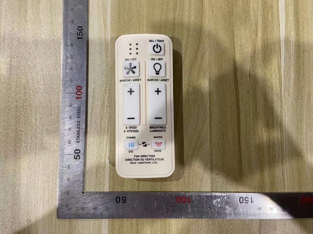
CEILING FAN REMOTE CONTROLLER TÉLÉCOMMANDE POUR VENTILATEUR DE PLAFOND MODEL:EHU-659OBT MODÈLE : EHU-659OBT Solid-State Fan Speed Control Contrôle de la vitesse du ventilateur à semi-conducteurs Use in ceiling fan only A utiliser uniquement pour un ventilateur de plafond Electrical rating: AC120V, 60Hz Caractéristiques de l’alimentation électrique : 120 V CA, 60 Hz MAX.motor amps: 1.0A Ampères MAX du moteur : 1,0A MAX.light watts: 24W Puissance MAX des lumières : 24W (Incandescent, CFL or LED for Light). (Incandescente, CFL ou LED pour la lumière). Made in China Fabriqué en Chine JIANGMEN KEYE ELECTRIC APPLIANCES MFG. CO. LTD. TO MOTOR L VERS LE FIL DE PHASE (L) DU MOTEUR TO MOTOR N VERS LE FIL NEUTRE (N) DU MOTEUR AC IN N ENTRÉE AC IN NEUTRE AC IN L ENTRÉE AC IN DE PHASE ANT ANTENNE BLOW AIR UPWARD SOUFFLE DE L'AIR VERS LE HAUT BLOW AIR DOWNWARD SOUFFLE L'AIR VERS LE BAS REVERSE THE COMMON LEAD VERS LES BORNES DU COMMUTATEUR LIGHT ANODES ANODES DE LA LUMIÈRE LIGHT CATHODE CATHODE DE LA LUMIÈRE 80*39 MODEL: EHU-669 FCC ID:2A377-669 IC ID:28128-669 MADE IN CHINA 49*24 MODÈLE: EHU-669 FCC ID:2A377-669 IC ID:28128-669 FABRIQUÉ EN CHINE This device complies with Part 15 of the FCC Rules. Operation is subject to the following two conditions: (1) this device may not cause harmful interference, and (2) this device must accept any interference received, including interference that may cause undesired operation.
Internal Photos
Appendix II Internal Photographs Page 2 of 3 UL Verification Services (Guangzhou) Co., Ltd, Song Shan Lake Branch This report shall not be reproduced except in full, without the written approval of UL Verification Services (Guangzhou) Co., Ltd, Song Shan Lake Branch. Internal View of EUT-1 Internal View of EUT-2 Antenna Page 3 of 3 UL Verification Services (Guangzhou) Co., Ltd, Song Shan Lake Branch This report shall not be reproduced except in full, without the written approval of UL Verification Services (Guangzhou) Co., Ltd, Song Shan Lake Branch. Internal View of EUT-3 Internal View of EUT-4
Test Report
The results reported herein have been performed in accordance with the laboratory’s terms of accreditation. This report shall not be reproduced except in full without the written approval of the Laboratory. The results in this report apply to the test sample(s) mentioned above at the time of the testing period only and are not to be used to indicate applicability to other similar products. CFR 47 FCC PART 15 SUBPART C ISED RSS-210 ISSUE 10 CERTIFICATION TEST REPORT For Remote Controller MODEL NUMBER: EHU-669 FCC ID: 2A377-669 IC: 28128-669 REPORT NUMBER: 4790227746.1-1 ISSUE DATE: February 18, 2022 Prepared for JIANGMEN KEYE ELECTRIC APPLIANCES MANUFACTURING CO., LTD. 1st, 3rd, 4th, 5th and 6th Building, NO.28, Jintong 8th Rd, Tangxia Town, Jiangme n, GD, China Prepared by UL Verification Services (Guangzhou) Co., Ltd, Song Shan Lake Branch Building 10, Innovation Technology Park, No. 1, Li Bin Road, Song Shan Lake Hi- Tech Development Zone Dongguan, 523808, People’s Republic of China Tel: +86 769 22038881 Fax: +86 769 33244054 Website: www.ul.com REPORT NO.: 4790227746.1-1 Page 2 of 36 UL Verification Services (Guangzhou) Co., Ltd, Song Shan Lake Branch FORM NO.: 10-SL-F0057 This report shall not be reproduced except in full, without the written approval of UL Verification Services (Guangzhou) Co., Ltd, Song Shan Lake Branch. Revision History Rev. Issue Date Revisions Revised By V0 02/18/2022 Initial Issue REPORT NO.: 4790227746.1-1 Page 3 of 36 UL Verification Services (Guangzhou) Co., Ltd, Song Shan Lake Branch FORM NO.: 10-SL-F0057 This report shall not be reproduced except in full, without the written approval of UL Verification Services (Guangzhou) Co., Ltd, Song Shan Lake Branch. Summary of Test Results Clau se Test Items FCC/ISED Rules Test Results 1 Transmitter Timeout CFR 47 FCC §15.231 (a) (1) ISED RSS-210 Annex A.1.1 Pass 2 20 dB Bandwidth and 99 % Occupied Bandwidth CFR 47 FCC §15.231 (c) ISED RSS-210 Annex A.1.3 Pass 3 Radiated Emission CFR 47 FCC §15.231 (b)(e) CFR 47 FCC §15.205 and §15.209 RSS-210 Annex A.1.2 RSS-GEN Clause 8.9 RSS-GEN Clause 8.10 Pass 4 Antenna Requirement CFR 47 FCC §15.203 ISED RSS-Gen Clause 6.3 Pass Note 1: This test report is only published to and used by the applicant, and it is not for evidence purpose in China. Note 2: The measurement result for the sample received is <Pass> according to < CFR 47 FCC PART 15 SUBPART C, ISED RSS-210 Issue 10 and ISED RSS-GEN Issue 5 > when <Accuracy Method> decision rule is applied. REPORT NO.: 4790227746.1-1 Page 4 of 36 UL Verification Services (Guangzhou) Co., Ltd, Song Shan Lake Branch FORM NO.: 10-SL-F0057 This report shall not be reproduced except in full, without the written approval of UL Verification Services (Guangzhou) Co., Ltd, Song Shan Lake Branch. TABLE OF CONTENTS 1. ATTESTATION OF TEST RESULTS ................................................................................. 5 2. TEST METHODOLOGY ..................................................................................................... 6 3. FACILITIES AND ACCREDITATION ................................................................................. 6 4. CALIBRATION AND UNCERTAINTY ................................................................................ 7 4.1. MEASURING INSTRUMENT CALIBRATION .............................................................. 7 4.2. MEASUREMENT UNCERTAINTY ............................................................................... 7 5. EQUIPMENT UNDER TEST ............................................................................................... 8 5.1. DESCRIPTION OF EUT .............................................................................................. 8 5.2. MAXIMUM FIELD STRENGTH .................................................................................... 8 5.3. TEST CHANNEL CONFIGURATION ........................................................................... 8 5.4. DESCRIPTION OF AVAILABLE ANTENNAS .............................................................. 8 5.5. TEST ENVIRONMENT ................................................................................................ 8 5.6. DESCRIPTION OF TEST SETUP ................................................................................ 9 5.7. MEASURING INSTRUMENT AND SOFTWARE USED ..............................................10 6. ANTENNA PORT TEST RESULTS ...................................................................................11 6.1. ON TIME AND DUTY CYCLE .....................................................................................11 6.2. TRANSMITTER TIMEOUT .........................................................................................15 6.3. 20 dB BANDWIDTH AND 99 % OCCUPIED BANDWIDTH ........................................17 6.4. RADIATED TEST RESULTS ......................................................................................21 6.4.1. FIELD STRENGTH AND SPURIOUS EMISSIONS BELOW 1 GHz AND ABOVE 30 MHz 29 6.4.2. SPURIOUS EMISSIONS ABOVE 1 GHz .............................................................31 6.4.3. SPURIOUS EMISSIONS BELOW 30 MHz ..........................................................33 7. ANTENNA REQUIREMENTS ............................................................................................36 REPORT NO.: 4790227746.1-1 Page 5 of 36 UL Verification Services (Guangzhou) Co., Ltd, Song Shan Lake Branch FORM NO.: 10-SL-F0057 This report shall not be reproduced except in full, without the written approval of UL Verification Services (Guangzhou) Co., Ltd, Song Shan Lake Branch. 1. ATTESTATION OF TEST RESULTS Applicant Information Company Name: JIANGMEN KEYE ELECTRIC APPLIANCES MANUFACTURING CO., LTD. Address: 1st, 3rd, 4th, 5th and 6th Building, NO.28, Jintong 8th Rd, Tangxia To wn, Jiangmen, GD, China Manufacturer Information Company Name: JIANGMEN KEYE ELECTRIC APPLIANCES MANUFACTURING CO., LTD. Address: 1st, 3rd, 4th, 5th and 6th Building, N…
Text truncated - open the document above for the full version.
Test Setup Photos
Appendix III Setup Photographs Radiated Disturbance Below 1 GHz and Above 30 MHz Radiated Disturbance Below 30 MHz RADIATED RF MEASUREMENT SETUP (Above 1 GHz – X axis) RADIATED RF MEASUREMENT SETUP (Above 1 GHz – Y axis) RADIATED RF MEASUREMENT SETUP (Above 1 GHz – Z axis)
Contact Information
Applicant
GuiQing Zhang(Engineer)
Test Firm
UL Verification Services (Guangzhou) Co., Ltd.Stephen Guo
[email protected]+86 0769 33817120
Technical Specifications
| # | Rule Parts | Frequency Range | Power Output |
|---|---|---|---|
| 1 | 15.231 | 433.92 MHz - 433.92 MHz | - |
Other Applications from JIANGMEN KEYE ELECTRIC APPLIANCES MANUFACTURING CO., LTD.
2A377-398SRF
Oct 10, 2024Remote Control
Equipment Class
DSC - Part 15 Security/Remote Control Transmitter