2A38RDAP620HIT Dragonfly Access Point
Belden Hirschmann Industries (Suzhou) Ltd.
Click to zoom
Application Details
- Equipment Class
- NII - Unlicensed National Information Infrastructure TX
- Date of Grant
- Apr 05, 2022
- Application Purpose
- Original Equipment
- Date of Application
- Mar 26, 2022
- Equipment Note
- HIT Dragonfly Access Point
- Frequency Range
- 5745.00000000 - 5825.00000000
- Country
- China
Documents & Files
Document Text
Text extracted from the exhibit documents filed with the FCC. Open a document above to read the original.
Users Manual
Quick Start Guide Version:V1.0 Model:DAP620-RW Contacting Website:www.belden.com Even if not specifically stated, the copyrighted trademark names in this manual shall not be deemed free of charge in the sense of the trademark and trade name protection act and thus freely available to anyone. © 2022 Belden Singapore Pte Ltd Both the manual and software are protected by copyright. All rights reserved. All or any part of this manual shall be prohibited from being reproduced, copied, translated or converted into any electronic media or machine-scannable form, except in the case that you make a copy of the software for your own use. The performance characteristics described herein shall be binding only upon the express consent of the parties at the time of signing the contract. This paper is produced by Belden within its capacity. Belden reserves the right to change the contents of this manual without prior notice. Belden does not guarantee the correctness or accuracy of the information in this manual. Belden shall not be liable for damages caused by the use of network components or related operating software. And the conditions of use specified in the license contract are referred to in this manual. You may access the latest version of this manual at the product website of Hirschmann IT: https://catalog.belden.com Belden Hirschmann 2 Quick Start Guide This Quick Start Guide assists you in quickly connecting to and configuring DAP. To learn more please refer to the DAP User Manual. DAP can be also managed by DAC platform, please refer to the DAC User Manual. Note ⚫ To keep DAP working in Cluster mode, please ensure there is no DHCP option 43 and 138 in the network. With DHCP option 43 or 138, the DAP comes up in DAC mode. 1. Typical topology Figure 1: Wi-Fi Network Topology 1. All APs connect to a PoE switch and the PoE switch connect to a router which provides DHCP service for APs and Wi-Fi users. Belden Hirschmann 3 2. If AP receives option 43 or option 138 from the DHCP server specifying the management IP, the AP will boot up and entering to DAC mode. Else the AP will enter Cluster mode. 3. APs in one cluster should be in the same Layer 2 network. (Tip: You can firstly config one AP then power on others to join the cluster automatically.) 4. If DAP couldn’t finish initialization, please check • Ethernet cable status • POE is enabled on the switch port that AP connected. 2. AP Initialization Step 1: How to Access AP Web Page By default, DAP will broadcast the WLAN ‘mywifi-xxxx’ (xxxx = the last two bytes of the AP MAC address). You can connect to ‘mywifi-xxxx’ and browse http://find.dragonflyap.com:8080 to access the AP web page. Figure 2: AP Login Page Recommend to access AP web Page by Chrome Browser for best user experience. Belden Hirschmann 4 Step 2: About Login Accounts Choose Administrator and default password is admin. Login AP web page, and you can access Figure 3. Select “Cluster” to cluster mode, or you can select “DAC” to DAC mode. Figure 3: AP Wizard - Mode Selection There are three pre-configured login accounts: Administrator, Viewer and GuestOperator. You may modify the account password, but the account name isn’t modifiable. Administrator can configure and check the AP status, Viewer can check the AP status ONLY, while GuestOperator can check the AP status and register accounts for portal authentication. By default, the password for all accounts is ‘admin’ and the wizard will guide you to modify the Administrator password upon AP login. More detailed configuration guide, please refer to DAP User Manual. Step 3: Welcome Page When initially logging into an AP from Figure 3, a configuration wizard will pop up. The following steps show how to use the setup wizard to modify the Administrator password and create a WLAN. Belden Hirschmann 5 Figure 4: AP Wizard - Welcome Page Belden Hirschmann 6 Step 4: Modify Administrator Password The password must be composed of numbers and capital or lower-case letters of the English alphabet and with a length of 4-16 characters. Figure 5: AP Wizard - Modify Admin Password Note: The page below will be displayed to select the country or region. Figure 6: AP Wizard - County/Region Page Step 5: Create New WLAN For example, create a WLAN, “DAP_MGMT”for network management purpose, select ‘Both (WPA&WPA2)’ security method and set the password to be ‘abc123!#’. By default, portal authentication is disabled when creating a WLAN. If you want to enable the portal page authentication, please refer to the User Manual for details. Belden Hirschmann 7 Figure 7: AP Wizard - Create WLAN Step 6: Confirmation Page After you complete AP initialization with the Wizard, the WLAN “mywifi-xxxx” will be deleted. You can then connect to the “DAP_MGMT” WLAN to continue with other configuration tasks. Figure 8: AP Wizard - Notice Belden Hirschmann 8 Installation Guide The document describes the product package, hardware overview, installation steps and precautions. Please read the complete document before installation. Summary of Installation Steps • WLAN Planning. Usually, a comprehensive site survey is required before installation, such as installation location, brackets, cables, power source, etc. • Unpack the AP box and check all contents • Install the AP bracket on ceiling or wall • Installing the AP • Connecting required cables • Power connection • Verifying post-installation connectivity • AP provisioning Package Contents Item Name Qty Unit 1 Access Point 1 Pcs 2 Manual 1 Pcs 3 Indoor mounting kit, Type W wall and ceiling mounting with screws. 1 Set Belden Hirschmann 9 Figure1: Product Packing Inform your sales representative of incorrect, missing, or damaged parts. If possible, retain the carton, including the original packing materials. Use these materials to repack and return the unit to the supplier if needed Hardware Overview ◆ Front View The access point is equipped with hidden LED display that indicates different status with different color. Figure 2 Hidden …
Text truncated - open the document above for the full version.
External Photos
Report No.: 2201RSU007-UE 1 of 7 EUT Photograph (1) EUT Photo (Model of test mode 3&4 in the original report) (2) EUT Photo (Model of test mode 3&4 in the original report) Report No.: 2201RSU007-UE (3) EUT Photo (Model of test mode 3&4 in the original report) (4) EUT Photo (Model of test mode 3&4 in the original report) Report No.: 2201RSU007-UE (5) EUT Photo (Model of test mode 3&4 in the original report) (6) EUT Photo (Model of test mode 3&4 in the original report) Report No.: 2201RSU007-UE (7) EUT Photo (Model of test mode 3&4 in the original report) (8) EUT Photo (DAP620-RW) Report No.: 2201RSU007-UE (9) EUT Photo (DAP620-RW) (10) EUT Photo (DAP620-RW) Report No.: 2201RSU007-UE (11) EUT Photo (DAP620-RW) (12) EUT Photo (DAP620-RW) Report No.: 2201RSU007-UE (13) EUT Photo (DAP620-RW) (14) EUT Photo (DAP620-RW)
External Photos
Report No.: 2202TW0004-UE 1 of 7 EUT Photograph (1) EUT Photo (Original model) (2) EUT Photo (Original model) Report No.: 2202TW0004-UE (3) EUT Photo (Original model) (4) EUT Photo (Original model) Report No.: 2202TW0004-UE (5) EUT Photo (Original model) (6) EUT Photo (Original model) Report No.: 2202TW0004-UE (7) EUT Photo (Original model) (8) EUT Photo (DAP620-RW) Report No.: 2202TW0004-UE (9) EUT Photo (DAP620-RW) (10) EUT Photo (DAP620-RW) Report No.: 2202TW0004-UE (11) EUT Photo (DAP620-RW) (12) EUT Photo (DAP620-RW) Report No.: 2202TW0004-UE (13) EUT Photo (DAP620-RW) (14) EUT Photo (DAP620-RW)
ID Label/Location Info
Label Location
Internal Photos
Report No.: 2201RSU007-UE 1 of 6 EUT Photograph (1) EUT Photo (2) EUT Photo Report No.: 2201RSU007-UE (3) EUT Photo (4) EUT Photo Report No.: 2201RSU007-UE (5) EUT Photo (6) EUT Photo Report No.: 2201RSU007-UE (7) EUT Photo (8) EUT Photo Report No.: 2201RSU007-UE (9) EUT Photo (10) EUT Photo RF IC Report No.: 2201RSU007-UE (11) EUT Photo
Internal Photos
Report No.: 2202TW0004-UE 1 of 6 EUT Photograph (1) EUT Photo (2) EUT Photo Report No.: 2202TW0004-UE (3) EUT Photo (4) EUT Photo Report No.: 2202TW0004-UE (5) EUT Photo (6) EUT Photo Report No.: 2202TW0004-UE (7) EUT Photo (8) EUT Photo Report No.: 2202TW0004-UE (9) EUT Photo (10) EUT Photo RF IC Report No.: 2202TW0004-UE (11) EUT Photo
RF Exposure Info
MRT Technology (Taiwan) Co., Ltd Report No.: 2202TW0004-U4 Phone: +886-3-3288388 Report Version: V1.0 Web: www.mrt-cert.com Issue Date: 2022-03-22 Page Number: 1 of 9 RF Exposure Evaluation Declaration FCC ID: 2A38RDAP620 Applicant: Belden Hirschmann Industries (Suzhou) Ltd. Application Type: Certification Product: HIT Dragonfly Access Point Model No.: DAP620-RW, DAP620-ME, DAP620-US, DAP620-JP Brand Name: HIRSCHMANN IT FCC Classification: Digital Transmission System (DTS) Unlicensed National Information Infrastructure (NII) Receive Date August 25, 2020 Test Date: November 18, 2020 Tested By : ( Fran Chen ) Reviewed By : ( Paddy Chen ) Approved By : ( Chenz Ker) The test results relate only to the samples tested. The test results shown in the test report are traceable to the national/international standards through the calibration of the equipment and evaluated measurement uncertainty herein. The test report shall not be reproduced except in full without the written approval of MRT Technology (Taiwan) Co., Ltd. Report No.: 2202TW0004-U4 Page Number: 2 of 9 Revision History Report No. Version Description Issue Date Note 2202TW0004-U4 V1.0 Initial Report 2022-03-22 Valid Report No.: 2202TW0004-U4 Page Number: 3 of 9 CONTENTS Description Page 1. INTRODUCTION ...................................................................................... 5 1.1. Scope ........................................................................................................................ 5 1.2. MRT Test Location .................................................................................................. 5 2. PRODUCT INFORMATION ...................................................................... 6 2.1. Feature of Equipment under Test ......................................................................... 6 2.2. Description of Available Antennas ........................................................................ 6 3. RF Exposure Evaluation ........................................................................ 7 3.1. Limits ......................................................................................................................... 7 3.2. Test Result of RF Exposure Evaluation ............................................................... 8 Appendix A - EUT Photograph ..................................................................... 9 Report No.: 2202TW0004-U4 Page Number: 4 of 9 §2.1033 General Information Applicant Belden Hirschmann Industries (Suzhou) Ltd. Applicant Address 333 Yanhu Road, Huaqiao Town, Kunshan City, Jiangsu Province, P. R. China Manufacturer Belden Hirschmann Industries (Suzhou) Ltd. Manufacturer Address 333 Yanhu Road, Huaqiao Town, Kunshan City, Jiangsu Province, P. R. China Test Site MRT Te c h n o l o g y ( Ta i w a n ) C o . , L t d Test Site Address No. 38, Fuxing Second Rd., Guishan Dist., Taoyuan City 333, Ta i w a n ( R . O . C ) MRT FCC Registration No. 291082 FCC Rule Part(s) 2.1091 Model No. DAP620-RW Test Device Serial No.: #1 Production Pre-Production Engineering Test Facility / Accreditations 1. MRT facility is an FCC registered (Reg. No. 291082) test facility with the site description report on file and is designated by the FCC as an Accredited Test Firm. 2. MRT facility is an IC registered (MRT Reg. No. 21723) test laboratory with the site description on file at Industry Canada. 3. MRT Lab is accredited to ISO 17025 by the Taiwan Accreditation Foundation (TAF Cert. No. 3261) in EMC, Telecommunications and Radio testing for FCC (Designation Number: TW3261), Industry Taiwan, EU and TELEC Rules. Report No.: 2202TW0004-U4 Page Number: 5 of 9 1. INTRODUCTION 1.1. Scope Measurement and determination of electromagnetic emissions (EMC) of radio frequency devices including intentional and/or unintentional radiators for compliance with the technical rules and regulations of the Federal Communications Commission and the Innovation, Science and Economic Development Canada and Certification and Engineering Bureau. 1.2. MRT Test Location The map below shows the location of the MRT LABORATORY, its proximity to the Taoyuan City. These measurement tests were conducted at the MRT Technology (Taiwan) Co., Ltd. Facility located at No.38, Fuxing 2nd Rd., Guishan Dist., Taoyuan City 33377, Taiwan (R.O.C). Report No.: 2202TW0004-U4 Page Number: 6 of 9 2. PRODUCT INFORMATION 2.1. Feature of Equipment under Test 2.2. Description of Available Antennas Antenna Type Frequency Band (GHz) T X Paths Bandwidth (MHz) Max Peak Gain (dBi) CDD Directional Gain (dBi) Beamforming Directional Gain (dBi) Ant 0 Ant 1 Power PSD Wi-Fi Internal Antenna List (2.4GHz 2*2 MIMO, 5GHz 2*2 MIMO) PIFA Antenna 2412 ~ 2462 2 20, 40 3.20 3.30 3.30 6.31 6.31 5150 ~ 5850 2 20, 40, 80 3.10 3.30 3.30 6.31 6.31 Note 1: The EUT supports Cyclic Delay Diversity (CDD) technology for 802.11a/b/g/n/ac/ax and it is correlated. If all antennas have the same gain, G ANT , Directional gain = G ANT + Array Gain, where Array Gain is as follows. l For power spectral density (PSD) measurements on all devices, Array Gain = 10 log (N ANT / N SS ) dB = 3.01; l For power measurements on IEEE 802.11 devices, Array Gain = 0 dB for N ANT ≤ 4; If antenna gains are not equal, Directional gain may be calculated by using the formulas applicable to equal gain antennas with G ANT set equal to the gain of the antenna having the highest gain. Note 2: The EUT also supports Beamforming mode, and the Beamforming support 802.11n/ac/ax, not include 802.11a/b/g. The directional gain = G ANT + Array Gain (3.01dBi). Note 3: Antenna type and antenna gain are provided by the manufacturer. Product Name HIT Dragonfly Access Point Model No. DAP620-RW, DAP620-ME, DAP620-US, DAP620-JP Brand Name: HIRSCHMANN IT Wi-Fi Specification: 802.11a/b/g/n/ac/ax Operating Temperature: 0 ~ 50 °C Power Type: PoE input or AC adapter input Operating Environment: Indoor Use Remark: 1. AC Power Adapter and PoE Injector are not sold with the product. 2. D…
Text truncated - open the document above for the full version.
Test Report
MRT Technology (Taiwan) Co., Ltd Report No.: 2202TW0004-U2 Phone: +886-3-3288388 Report Version: V1.0 Web: www.mrt-cert.com Issue Date: 2022-03-22 FCC ID: 2A38RDAP620 Page Number: 1 of 380 FCC ID: 2A38RDAP620 Applicant: Belden Hirschmann Industries (Suzhou) Ltd. Application Type: Certification Product: HIT Dragonfly Access Point Model No.: DAP620-RW, DAP620-ME, DAP620-US, DAP620-JP Brand Name: HIRSCHMANN IT FCC Classification: Unlicensed National Information Infrastructure (NII) FCC Rule Part(s): Part15 Subpart E (Section 15.407) Test Procedure(s): ANSI C63.10-2013 Receive Date August 25, 2020 Test Date: October 17 ~ November 30, 2020 MEASUREMENT REPORT FCC PART 15.407 WLAN 802.11a/n/ac/ax Test ed By : (Fran Chen) Reviewed By : (Paddy Chen) Approved By : (Chenz Ker) The test results relate only to the samples tested. This equipment has been shown to be capable of compliance with the applicable technical standards as indicated in the measurement report and was tested in accordance with the measurement procedures specified in ANSI C63.10-2013. Te s t r e s u l t s r e p o r t e d h e r e in relate only to the item(s) tested. The test report shall not be reproduced except in full without the written approval of MRT Technology (Taiwan) Co., Ltd. Report No.:2 202TW0004-U2 FCC ID: 2A38RDAP620 Page Number: 2 of 380 Revision History Report No. Version Description Issue Date Note 2202TW0004-U2 V1.0 Initial Report 2022-03-22 Valid Note: This is a copy report based on MRT original report (report No.: 2010TW0002-UF). It changed the information of the applicant and the product. The hardware and software of the product are the same. Only a slight change in appearance, which has no impact on the test results. Report No.:2 202TW0004-U2 FCC ID: 2A38RDAP620 Page Number: 3 of 380 CONTENTS Description Page 1. INTRODUCTION ........................................................................................................................ 7 1.1. Scope .............................................................................................................................. 7 1.2. MRT Test Location .......................................................................................................... 7 2. PRODUCT INFORMATION ........................................................................................................ 8 2.1. Equipment Description .................................................................................................... 8 2.2. Product Specification Subjective to this Report .............................................................. 8 2.3. Working Frequencies for this report ................................................................................ 9 2.4. Description of Available Antennas ................................................................................. 10 2.5. Description of Antenna RF Port .................................................................................... 10 2.6. Test Mode ..................................................................................................................... 10 2.7. Description of Test Software ......................................................................................... 10 2.8. Duty Cycle ..................................................................................................................... 11 2.9. EMI Suppression Device(s)/Modifications ..................................................................... 12 2.10. Configuration of Tested System .................................................................................... 13 2.11. Test System Details ...................................................................................................... 13 3. ANTENNA REQUIREMENTS .................................................................................................. 14 4. TEST EQUIPMENT CALIBRATION DATE .............................................................................. 15 5. MEASUREMENT UNCERTAINTY ........................................................................................... 17 6. TEST RESULT ......................................................................................................................... 18 6.1. Summary ....................................................................................................................... 18 6.2. 26dB Bandwidth Measurement ..................................................................................... 19 6.2.1. Te s t L i m i t ....................................................................................................................... 19 6.2.2. Te s t Procedure used ..................................................................................................... 19 6.2.3. Te s t Setting ................................................................................................................... 19 6.2.4. Te s t S e t u p ..................................................................................................................... 19 6.2.5. Te s t R e s ult .................................................................................................................... 20 6.3. 6dB Bandwidth Measurement ....................................................................................... 35 6.3.1. Te s t L i m i t ....................................................................................................................... 35 6.3.2. Te s t P r o c e d u r e u s e d ..................................................................................................... 35 6.3.3. Te s t Setting ................................................................................................................... 35 6.3.4. Te s t S e t u p ..................................................................................................................... 35 6.3.5. Te s t Result ....................................................…
Text truncated - open the document above for the full version.
Test Report
Report No.:2 202TW0004-U2 FCC ID: 2A38RDAP620 Page Number: 34 of 380 802.11ax-HE80 26dB Bandwidth & 99% Bandwidth Channel 42 (5210MHz) Channel 58 (5290MHz) Channel 106 (5530MHz) Channel 122 (5610MHz) Channel 138 (5690MHz) Channel 155 (5775MHz) Report No.:2 202TW0004-U2 FCC ID: 2A38RDAP620 Page Number: 35 of 380 6.3. 6dB Bandwidth Measurement 6.3.1.Test Limit The minimum 6dBbandwidth shall be at least 500 kHz. 6.3.2.Test Procedure used KDB 789033 D02v02r01- Section C.2 6.3.3.Test Setting 1. Set center frequency to the nominal EUT channel center frequency. 2. RBW = 100 kHz. 3. VBW≧ 3 × RBW. 4. Detector = Peak. 5. Trace mode = max hold. 6. Sweep = auto couple. 7. Allow the trace to stabilize. 8. Measure the maximum width of the emission that is constrained by the frequencies associated with the two outermost amplitude points (upper and lower frequencies) that are attenuated by 6 dB relative to the maximum level measured in the fundamental emission. 6.3.4.Test Setup Report No.:2 202TW0004-U2 FCC ID: 2A38RDAP620 Page Number: 36 of 380 6.3.5.Test Result Product HIT Dragonfly Access Point Te s t S i t e SR2 Te s t Engineer Eric Lin Te s t D a t e 2020/11 / 1 9 Te s t i t e m 6dB bandwidth (U-NII-3) Te s t M o d e Data Rate/ MCS Channel No. Frequency (MHz) 6dB Bandwidth (MHz) Limit (MHz) Result 802.11a 6Mbps 149 5745 15.93 ≥ 0.5 Pass 802.11a 6Mbps 157 5785 16.36 ≥ 0.5 Pass 802.11a 6Mbps 165 5825 16.38 ≥ 0.5 Pass 802.11ac-VHT20 MCS0 149 5745 17.65 ≥ 0.5 Pass 802.11ac-VHT20 MCS0 157 5785 17.63 ≥ 0.5 Pass 802.11ac-VHT20 MCS0 165 5825 17.60 ≥ 0.5 Pass 802.11ac-VHT40 MCS0 151 5755 36.44 ≥ 0.5 Pass 802.11ac-VHT40 MCS0 159 5795 36.41 ≥ 0.5 Pass 802.11ac-VHT80 MCS0 155 5775 72.89 ≥ 0.5 Pass 802.11ax-HE20 MCS0 149 5745 18.06 ≥ 0.5 Pass 802.11ax-HE20 MCS0 157 5785 18.19 ≥ 0.5 Pass 802.11ax-HE20 MCS0 165 5825 18.54 ≥ 0.5 Pass 802.11ax-HE40 MCS0 151 5755 37.79 ≥ 0.5 Pass 802.11ax-HE40 MCS0 159 5795 37.85 ≥ 0.5 Pass 802.11ax-HE80 MCS0 155 5775 76.34 ≥ 0.5 Pass Note: The Data only show the max power Antenna Port in the test report. Report No.:2 202TW0004-U2 FCC ID: 2A38RDAP620 Page Number: 37 of 380 802.11a 6dB Bandwidth Channel 149 (5745MHz) Channel 157 (5785MHz) Channel 165 (5825MHz) 802.11ac-VHT20 6dB Bandwidth Channel 149 (5745MHz) Channel 157 (5785MHz) Channel 165 (5825MHz) Report No.:2 202TW0004-U2 FCC ID: 2A38RDAP620 Page Number: 38 of 380 802.11ac-VHT40 6dB Bandwidth Channel 151 (5755MHz) Channel 159 (5795MHz) 802.11ac-VHT80 6dB Bandwidth Channel 155 (5775MHz) Report No.:2 202TW0004-U2 FCC ID: 2A38RDAP620 Page Number: 39 of 380 802.11ax-HE20 6dB Bandwidth Channel 149 (5745MHz) Channel 157 (5785MHz) Channel 165 (5825MHz) Report No.:2 202TW0004-U2 FCC ID: 2A38RDAP620 Page Number: 40 of 380 802.11ax-HE40 6dB Bandwidth Channel 151 (5755MHz) Channel 159 (5795MHz) 802.11ax-HE80 6dB Bandwidth Channel 155 (5775MHz) Report No.:2 202TW0004-U2 FCC ID: 2A38RDAP620 Page Number: 41 of 380 6.4. Output Power Measurement 6.4.1.Test Limit For the band 5.15-5.25 GHz, the maximum conductedoutput power over the frequency band of operation shall not exceed 1 W provided the maximumantenna gain does not exceed 6 dBi. For the 5.25-5.35 GHz and 5.47-5.725 GHz bands, the maximum conducted output power over the frequency bands of operation shall not exceed the lesser of 250 mW or 11 dBm + 10 log B, where B is the 26 dB emission bandwidth in megahertz. For the band 5.725-5.85 GHz, the maximum conducted output power over the frequency band of operation shall not exceed 1 W (30dBm). If transmitting antennas of directional gain greater than 6dBi are used, the maximumconducted output power shall be reduced by the amount in dB that the directional gain of theantenna exceeds 6dBi. 6.4.2.Test Procedure Used KDB 789033D02v02r01- Section E)3) b) Method PM-G 6.4.3.Test Setting Average power measurements were performed only when the EUT was transmitting at its maximum power control level using a broadband power meter with a pulse sensor. The power meter implemented triggering and gating capabilities which were set up such that power measurements were recorded only during the ON time of the transmitter. 6.4.4.Test Setup Report No.:2 202TW0004-U2 FCC ID: 2A38RDAP620 Page Number: 42 of 380 6.4.5.Test Result Product HIT Dragonfly Access Point Te s t S i t e SR2 Te s t Engineer Eric Lin Te s t D a t e 2020/11/18 Test item Output Power Te s t M o d e Data Rate/ MCS Channel No. Freq. (MHz) Ant 0 Average Power (dBm) Ant 1 Average Power (dBm) To t a l Average Power (dBm) Average Power Limit (dBm) Result 11a 6Mbps 36 5180 19.41 18.95 22.20 ≤ 29.69 Pass 11a 6Mbps 44 5220 19.77 19.59 22.69 ≤ 29.69 Pass 11a 6Mbps 48 5240 19.98 19.68 22.84 ≤ 29.69 Pass 11a 6Mbps 52 5260 18.31 18.05 21.19 ≤ 23.67 Pass 11a 6Mbps 60 5300 18.01 17.76 20.90 ≤ 23.67 Pass 11a 6Mbps 64 5320 17.50 17.41 20.47 ≤ 23.67 Pass 11a 6Mbps 100 5500 18.07 18.14 21.12 ≤ 23.67 Pass 11a 6Mbps 116 5580 17.03 16.94 20.00 ≤ 23.67 Pass 11a 6Mbps 140 5700 17.17 17.04 20.12 ≤ 23.67 Pass 11a 6Mbps 144 5720 17.02 17.17 20.11 ≤ 23.67 Pass 11a 6Mbps 149 5745 19.02 18.94 21.99 ≤ 29.69 Pass 11a 6Mbps 157 5785 18.82 19.05 21.95 ≤ 29.69 Pass 11a 6Mbps 165 5825 19.04 19.21 22.14 ≤ 29.69 Pass 11ac-VHT20 MCS0 36 5180 19.11 18.81 21.97 ≤ 29.69 Pass 11ac-VHT20 MCS0 40 5220 19.52 19.38 22.46 ≤ 29.69 Pass 11ac-VHT20 MCS0 48 5240 19.85 19.43 22.66 ≤ 29.69 Pass 11ac-VHT20 MCS0 52 5260 18.88 18.76 21.83 ≤23.67 Pass 11ac-VHT20 MCS0 60 5300 18.82 18.57 21.71 ≤23.67 Pass 11ac-VHT20 MCS0 64 5320 17.98 17.47 20.74 ≤23.67 Pass 11ac-VHT20 MCS0 100 5500 18.89 18.84 21.88 ≤23.67 Pass 11ac-VHT20 MCS0 116 5580 18.66 18.46 21.57 ≤23.67 Pass 11ac-VHT20 MCS0 140 5700 18.32 18.53 21.44 ≤23.67 Pass 11ac-VHT20 MCS0 144 5720 18.46 18.48 21.48 ≤23.67 Pass 11ac-VHT20 MCS0 149 5745 18.62 18.91 21.78 ≤ 29.69 Pass 11ac-VHT20 MCS0 157 5785 18.67 18.47 21.58 ≤ 29.69 Pass 11ac-VHT20 MCS0 165 5825 18.76 18.64 21.71 ≤ 29.69 Pass Report No.:2 202TW0004-U2 FCC ID: 2A38RDAP620 Page Number: 43 of 380 Te s t M o d e Data Rate/ MCS Channel No. Freq…
Text truncated - open the document above for the full version.
Test Report
Report No.:2 202TW0004-U2 FCC ID: 2A38RDAP620 Page Number: 61 of 380 802.11ax-HE40 Power Spectral Density - Ant 0 / Ant 0 + 1 Channel 38 (5190MHz) Channel 46 (5230MHz) Channel 54 (5270MHz) Channel 62 (5310MHz) Channel 102 (5510MHz) Channel 110 (5550MHz) Report No.:2 202TW0004-U2 FCC ID: 2A38RDAP620 Page Number: 62 of 380 Channel 134 (5670MHz) Channel 142 (5710MHz) Channel 151 (5755MHz) Channel 159 (5795MHz) Report No.:2 202TW0004-U2 FCC ID: 2A38RDAP620 Page Number: 63 of 380 802.11ax-HE80 Power Spectral Density - Ant 0 / Ant 0 + 1 Channel 42 (5210MHz) Channel 58 (5290MHz) Channel 106 (5530MHz) Channel 122 (5610MHz) Channel 138 (5690MHz) Channel 155 (5775MHz) Report No.:2 202TW0004-U2 FCC ID: 2A38RDAP620 Page Number: 64 of 380 802.11a Power Spectral Density - Ant 1 / Ant 0 + 1 Channel 36 (5180MHz) Channel 44 (5220MHz) Channel 48 (5240MHz) Channel 52 (5260MHz) Channel 60 (5300MHz) Channel 64 (5320MHz) Report No.:2 202TW0004-U2 FCC ID: 2A38RDAP620 Page Number: 65 of 380 Channel 100 (5500MHz) Channel 116 (5580MHz) Channel 140 (5700MHz) Channel 144 (5720MHz) Channel 149 (5745MHz) Channel 157 (5785MHz) Channel 165 (5825MHz) Report No.:2 202TW0004-U2 FCC ID: 2A38RDAP620 Page Number: 66 of 380 802.11ac-VHT20 Power Spectral Density - Ant 1 / Ant 0 + 1 Channel 36 (5180MHz) Channel 44 (5220MHz) Channel 48 (5240MHz) Channel 52 (5260MHz) Channel 60 (5300MHz) Channel 64 (5320MHz) Report No.:2 202TW0004-U2 FCC ID: 2A38RDAP620 Page Number: 67 of 380 Channel 100 (5500MHz) Channel 116 (5580MHz) Channel 140 (5700MHz) Channel 144 (5720MHz) Channel 149 (5745MHz) Channel 157 (5785MHz) Channel 165 (5825MHz) Report No.:2 202TW0004-U2 FCC ID: 2A38RDAP620 Page Number: 68 of 380 802.11ac-VHT40 Power Spectral Density - Ant 1 / Ant 0 + 1 Channel 38 (5190MHz) Channel 46 (5230MHz) Channel 54 (5270MHz) Channel 62 (5310MHz) Channel 102 (5510MHz) Channel 110 (5550MHz) Report No.:2 202TW0004-U2 FCC ID: 2A38RDAP620 Page Number: 69 of 380 Channel 134 (5670MHz) Channel 142 (5710MHz) Channel 151 (5755MHz) Channel 159 (5795MHz) Report No.:2 202TW0004-U2 FCC ID: 2A38RDAP620 Page Number: 70 of 380 802.11ac-VHT80 Power Spectral Density - Ant 1 / Ant 0 + 1 Channel 42 (5210MHz) Channel 58 (5290MHz) Channel 106 (5530MHz) Channel 122 (5610MHz) Channel 138 (5690MHz) Channel 155 (5775MHz) Report No.:2 202TW0004-U2 FCC ID: 2A38RDAP620 Page Number: 71 of 380 802.11ax-HE20 Power Spectral Density - Ant 1 / Ant 0 + 1 Channel 36 (5180MHz) Channel 44 (5220MHz) Channel 48 (5240MHz) Channel 52 (5260MHz) Channel 60 (5300MHz) Channel 64 (5320MHz) Report No.:2 202TW0004-U2 FCC ID: 2A38RDAP620 Page Number: 72 of 380 Channel 100 (5500MHz) Channel 116 (5580MHz) Channel 140 (5700MHz) Channel 144 (5720MHz) Channel 149 (5745MHz) Channel 157 (5785MHz) Channel 165 (5825MHz) Report No.:2 202TW0004-U2 FCC ID: 2A38RDAP620 Page Number: 73 of 380 802.11ax-HE40 Power Spectral Density - Ant 1 / Ant 0 + 1 Channel 38 (5190MHz) Channel 46 (5230MHz) Channel 54 (5270MHz) Channel 62 (5310MHz) Channel 102 (5510MHz) Channel 110 (5550MHz) Report No.:2 202TW0004-U2 FCC ID: 2A38RDAP620 Page Number: 74 of 380 Channel 134 (5670MHz) Channel 142 (5710MHz) Channel 151 (5755MHz) Channel 159 (5795MHz)
Test Report
Report No.:2 202TW0004-U2 FCC ID: 2A38RDAP620 Page Number: 75 of 380 802.11ax-HE80 Power Spectral Density - Ant 1 / Ant 0 + 1 Channel 42 (5210MHz) Channel 58 (5290MHz) Channel 106 (5530MHz) Channel 122 (5610MHz) Channel 138 (5690MHz) Channel 155 (5775MHz) Report No.:2 202TW0004-U2 FCC ID: 2A38RDAP620 Page Number: 76 of 380 6.7. Frequency Stability Measurement 6.7.1.TestLimit Manufactures of U-NII devices are responsible for ensuring frequency stability such that an emission is maintained within the band of operation under all conditions of normal operation as specified in the user’s manual. The transmitter center frequency tolerance shall be ±20 ppm maximum for the 5GHz band (IEEE 802.11 specification)…
Text truncated - open the document above for the full version.
Contact Information
Applicant
Peng Wang
Technical Contact
MRT Technology (Taiwan) Co., LtdChenz Ker
[email protected]+886-3-3288388
No. 38, Fuxing Second Rd., Guishan Dist., · Taoyuan · Taiwan
Non-Technical Contact
MRT Technology (Taiwan) Co., LtdChenz Ker
[email protected]+886-3-3288388
Test Firm
MRT Technology (Taiwan) Co.,LtdChenz Ker
Technical Specifications
| # | Rule Parts | Frequency Range | Power Output |
|---|---|---|---|
| 4 | 15E | 5.75 GHz - 5.83 GHz | 168.70 mW |
Other Applications from Belden Hirschmann Industries (Suzhou) Ltd.
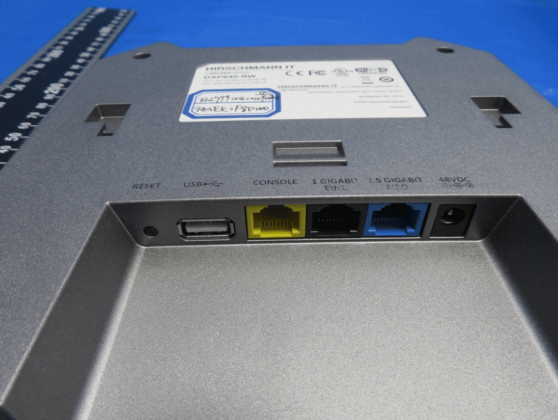
2A38RDAP640
May 09, 2022HIT Dragonfly Access Point
Equipment Class
NII - Unlicensed National Information Infrastructure TX