2A3BG-PHTMP5 Phantom controller
Shenzhen JinYangHuiChuang Technology Limited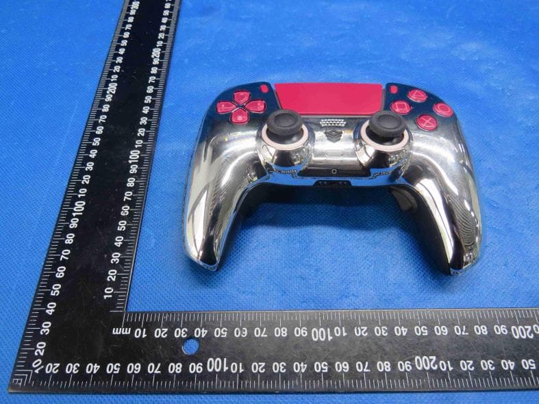
Click to zoom
Application Details
- Equipment Class
- DTS - Digital Transmission System
- Date of Grant
- May 05, 2023
- Application Purpose
- Original Equipment
- Date of Application
- May 05, 2023
- Equipment Note
- P5 Phantom controller
- Frequency Range
- 2402.00000000 - 2480.00000000
- Country
- China
Documents & Files
Document Text
Text extracted from the exhibit documents filed with the FCC. Open a document above to read the original.
Users Manual
Hardware part names Front ABDECCFG H JIKLNM A ) Directional buttons B ) (create) button C ) Light bar D ) Touch pad/touch pad button E ) Player indicator F ) (options) button G ) Action buttons button/ button/ button/ button H ) Right stick/R3 button I ) Speaker J ) (PS) button K ) Headset jack L ) Microphone M ) (MUTE) button N ) Left stick/L3 button To p EDCBA A ) R1 button B ) R2 button C ) USB port D ) L1 button E ) L2 button Pair the controller The first time you use the controller, you'll need to pair it with your PS5 console. 1 Turn on your console. 2 Connect the controller to your console using the USB cable included with your console. 3 Press the (PS) button. The controller powers on. After the light bar blinks, the player indicator lights up. Charge the controller Use the USB cable included with your console to connect the controller to your PS5 console when your console is turned on or in rest mode. While in rest mode, the light bar on the controller slowly blinks orange. When charging is complete, the light bar turns off. Hints ˎTo charge the controller while your console is in rest mode, you have to first enable this feature. For details, refer to the User's Guide on your PS5 console. ˎYou can also charge the controller by connecting the USB cable to a computer or other USB device. Use a USB cable that complies with the USB standard. You might not be able to charge the controller on some devices. –Limit the amount of time you use headset or headphones at high volume. –Avoid raising the volume to block out noisy surroundings. –Lower the volume if you can't hear people speaking near you. ˎWhen using headsets or headphones in particularly dry air conditions, you may sometimes experience a small and quick (static) shock on your ears. This is a result of static electricity accumulated in the body, and is not a malfunction of your headsets or headphones. ˎAvoid looking into the light bar of the controller when it is flashing. Stop using the controller immediately if you experience any discomfort or pain in any body parts. Use and handling ˎNever disassemble or modify the product. ˎDo not allow liquid, small particles or other foreign objects to get into the product. ˎDo not place the product on surfaces that are unstable, tilted or subject to vibration. ˎDo not use the product near water. ˎDo not touch the product during an electrical storm. ˎDo not stand on or put objects on the product. ˎDo not throw or drop the product or subject it to strong physical shock. ˎDo not place the product on the floor or in a place where they may cause someone to trip or stumble. ˎIf the wireless controller is sitting on a flat surface, the vibration of the wireless controller during gameplay may cause it to fall, leading to injury or malfunction. ˎDo not touch the ports or insert any foreign objects into the product. ˎIf you see dust or foreign objects on the connectors, wipe them with a dry cloth before connecting. ˎDo not touch the product with wet hands. ˎWhen using the motion sensor function, be cautious of the following points. If the controller hits a person or object, this may cause an accident, injury or damage. –Before using the motion sensor function, make sure you have enough space to move around. –Firmly grip the wireless controller to prevent it from slipping out of your grasp and causing damage or injury. –If using a controller that is connected to the PS5™ system with a USB cable, make sure that the cable will not hit a person or object. Also take care to avoid pulling out the cable from the PS5 console. ˎThe product and its parts are made from metal and plastic materials. When disposing of the product, follow local regulations for the proper disposal of such materials. Cleaning Follow the instructions below to help prevent the product exterior from deteriorating or becoming discoloured. ˎWipe with a soft, dry cloth. ˎDo not apply insecticides or other volatile substances. ˎDo not place any rubber or vinyl materials on the product exterior for an extended period of time. ˎDo not use solvents or other chemicals. Do not wipe with a chemically-treated cleaning cloth. Storage conditions ˎDo not expose the product to high temperatures, high humidity or direct sunlight during operation, transportation and storage. ˎDo not leave the product in a car with the windows closed, particularly in hot weather. ˎDo not expose the product to dust, smoke or steam. Battery life and duration ˎThe battery has a limited lifespan. Battery duration will gradually decrease with repeated usage and age. Battery life also varies depending on the storage method, conditions of use and environmental factors. ˎCharge in an environment where the temperature range is between 10 °C and 30 °C. Charging may not be as effective when performed in other environments. When not in use When the wireless controller is not used for an extended period of time, it is recommended that you fully charge it at least once a year to help maintain battery functionality. When disposing of the wireless controller The lithium-ion battery of the wireless controller is recyclable. When disposing of the wireless controller, remove the battery and follow local regulations regarding disposing of batteries. Caution ˎRemove the battery in a location out of the reach of small children to help prevent accidental swallowing of small parts such as the screws. ˎBe careful not to hurt your nails or fingers when removing the controller casing. ˎFor safety reasons, attach tape or a seal on the metal part of the battery before disposing. Notice Other than when disposing of the wireless controller, never remove the screws and never remove the battery from the wireless controller. 1 Disconnect the USB cable from the wireless controller. 2 Remove the cover on the front of the controller. Cover 3 Using a tool such as a screwdriver, remove the L1 and R1 buttons. L1 button R1 button 4 Using a crosshead screwdriver, remove the screws (4 places). 5 Using a tool s…
Text truncated - open the document above for the full version.
Cover Letter(s)
Sincerely, Name/Title: YiHui Zhan /Manager Company: Shenzhen JinYangHuiChuang Technology Limited Address: #1301, ShenXinTaifeng Building, Qianjin 1st Road No 86, Baoan District Shenzhen, Guangdong China Phone: +86 0755-83623870 Fax: +86 0755-83623870 E-Mail: [email protected]
External Photos
Shenzhen HTT Technology Co., Ltd. Report No.: HTT202303321 Shenzhen HTT Technology Co.,Ltd. Tel: 0755-23595200 Fax: 0755-23595201 1F, Building B, Huafeng International Robotics Industrial Park,Hangcheng Road, Nanchang Community, Xixiang Street, Bao'an District, Guangdong Province, Shenzhen, China Page 1 of 3 Product Name: P5 Phantom controller Model No.: PHTM EUT Constructional Details External Photo Report No.: HTT202303321 Shenzhen HTT Technology Co.,Ltd. Tel: 0755-23595200 Fax: 0755-23595201 1F, Building B, Huafeng International Robotics Industrial Park,Hangcheng Road, Nanchang Community, Xixiang Street, Bao'an District, Guangdong Province, Shenzhen, China Page 2 of 3 Report No.: HTT202303321 Shenzhen HTT Technology Co.,Ltd. Tel: 0755-23595200 Fax: 0755-23595201 1F, Building B, Huafeng International Robotics Industrial Park,Hangcheng Road, Nanchang Community, Xixiang Street, Bao'an District, Guangdong Province, Shenzhen, China Page 3 of 3 ------End------
ID Label/Location Info
Label and Location Size: L: 1.0cm*W: 0.5cm Label and Location FCC ID : 2A3BG-PHTM
Internal Photos
Shenzhen HTT Technology Co., Ltd. Report No.: HTT202303321 Shenzhen HTT Technology Co.,Ltd. Tel: 0755-23595200 Fax: 0755-23595201 1F, Building B, Huafeng International Robotics Industrial Park,Hangcheng Road, Nanchang Community, Xixiang Street, Bao'an District, Guangdong Province, Shenzhen, China Page 1 of 4 Product Name: P5 Phantom controller Model No.: PHTM EUT Constructional Details Internal Photo Report No.: HTT202303321 Shenzhen HTT Technology Co.,Ltd. Tel: 0755-23595200 Fax: 0755-23595201 1F, Building B, Huafeng International Robotics Industrial Park,Hangcheng Road, Nanchang Community, Xixiang Street, Bao'an District, Guangdong Province, Shenzhen, China Page 2 of 4 Report No.: HTT202303321 Shenzhen HTT Technology Co.,Ltd. Tel: 0755-23595200 Fax: 0755-23595201 1F, Building B, Huafeng International Robotics Industrial Park,Hangcheng Road, Nanchang Community, Xixiang Street, Bao'an District, Guangdong Province, Shenzhen, China Page 3 of 4 Report No.: HTT202303321 Shenzhen HTT Technology Co.,Ltd. Tel: 0755-23595200 Fax: 0755-23595201 1F, Building B, Huafeng International Robotics Industrial Park,Hangcheng Road, Nanchang Community, Xixiang Street, Bao'an District, Guangdong Province, Shenzhen, China Page 4 of 4 ------End------
RF Exposure Info
RF Exposure evaluation FCC ID: 2A3BG-PHTM 1.1. Applicable Standard According to §1.1307(b)(1), systems operating under the provisions of this section shall be operated in a manner that ensures that the public is not exposed to radio frequency energy level in excess of the Commission’s guidelines. According to §1.1310 and §2.1093 RF exposure requirement KDB447498 v06: Mobile and Portable Devices RF Exposure Procedures and Equipment Authorization Policies 1.2. Requirement According to KDB447498 D01 General RF Exposure Guidance v06 Section 4.3.1 Standalone SAR test exclusion considerations: “Unless specifically required by the published RF exposure KDB procedures, standalone 1-g head or body and 10-g extremity SAR evaluation for general population exposure conditions, by measurement or numerical simulation, is not required when the corresponding SAR Test Exclusion Threshold condition, listed below, is satisfied. These test exclusion conditions are based on source-based time-averaged maximum conducted output power of the RF channel requiring evaluation, adjusted for tune-up tolerance, and the minimum test separation distance required for the exposure conditions.22 The minimum test separation distance is determined by the smallest distance from the antenna and radiating structures or outer surface of the device, according to the host form factor, exposure conditions and platform requirements, to any part of the body or extremity of a user or bystander (see 5) of section 4.1). To qualify for SAR test exclusion, the test separation distances applied must be fully explained and justified by the operating configurations and exposure conditions of the transmitter and applicable host platform requirements, typically in the SAR measurement or SAR analysis report, according to the required published RF exposure KDB procedures. When no other RF exposure testing or reporting is required, a statement of justification and compliance must be included in the equipment approval, in lieu of the SAR report, to qualify for the SAR test exclusion. When required, the device specific conditions described in the other published RF exposure KDB procedures must be satisfied before applying these SAR test exclusion provisions; for example, handheld PTT two-way radios, handsets, laptops & tablets etc.23 “ [(max. power of channel, including tune-up tolerance, mW)/ (min. test separation distance, mm)] · [√f (GHz)] ≤ 3.0 for 1-g SAR and ≤ 7.5 for 10-g extremity SAR, where: • f (GHz) is the RF channel transmit frequency in GHz • Power and distance are rounded to the nearest mW and mm before calculation • The result is rounded to one decimal place for comparison • 3.0 and 7.5 are referred to as the numeric thresholds in the step 2 below The test exclusions are applicable only when the minimum test separation distance is ≤ 50 mm and for transmission frequencies between 100 MHz and 6 GHz. When the minimum test separation distance is < 5 mm, a distance of 5 mm according to 5) in section 4.1 is applied to determine SAR test exclusion. 1.3. Manufacturing tolerance GFSK (Peak) Channel Channel 0 Channel 19 Channel 39 Target (dBm) 1.0 1.0 0.0 Tolerance ±(dB) 1.0 1.0 1.0 Page 2 of 2 2. E v a l u a t i o n R e s u l t Evaluation Results Band/Mode f (GHz) Antenna Distance (mm) RF output power (including tune-up tolerance) SAR Test Exclusion Threshold SAR Test Exclusion dBm mW BT 2.450 5 2.0 1.5849 0.4962<3.0 Yes 3. C o n c l u s i o n The measurement results comply with the FCC Limit per 47 CFR 2.1093 for the uncontrolled RF Exposure and SAR Exclusion Threshold per KDB 447498 v06 .....................End of Report.........................
Test Report
2013 /05/ 222 Antenna Copyri a spe ight 2013© Sh ecific henzhen Innos ation systemTechno All ologyLimited rights reserv eed. 2013/05 / 2 Ante APP ※B ※I 1.Di ‣Com ‣Com 22 enna model: lication Bluetoot ISM band mensions mpany Name mpany addre : MARB AT ns th Home d 2.4GHz s e ess T V1.0 RF z applic Shen F2 B Rd Gao X Copyri cations nzhen Innosy uilding 3 Sh Xin Science ight 2013© Sh ystem Techn henzhen So & Technolo g henzhen Innos nology Ltd ftware Park gy Park Nort systemTechno All k Technology th, S.Z ologyLimited rights reserv e y Middle 2 ed. 2 013/05/ 2 2.Sp number 1 2 3 4 5 6 7 8 3.si ① V Mk 22 ecificat mulation SWR r1: 239 7 tions Working A Azim Mod n paramet 7MHz 1.47 Item Central F Band Widt Gain VSWR Antenna ty muth Beam Impedance dulation m ter 7 Mkr2 Copyri Frequency th ype width e mode : 2450MH ight 2013© Sh Hz 1.51 henzhen Innos Sp (2 P Omni Mkr3: 24 systemTechno All ecificati 2441 MHz 402-2480) 0dBi ≤2.0 PCB antenn i‐directi 50ohm GFSK 482 MHz ologyLimited rights reserv e ons MHz na ional 1.59 ed. 2 013/05/ 2 ②Sm Mkr 22 ith Char 1: 2397M r MHz 73.4 Mkr2 Copyri : 2450MH ight 2013© Sh Hz 62.7 henzhen Innos Mkr3: 2 systemTechno All 2482MHz ologyLimited rights reserv e 66.8 ed. 2 013/05/ 2 ③Re Mkr 22 turn Los 1: 2397M ss MHz -15 Mkr2: Copyri 2450MHz ight 2013© Sh z -18 M henzhen Innos Mkr3: 248 systemTechno All 82 MHz - ologyLimited rights reserv e -16 ed. 2 013/05/ 2 ④Sm Mkr 22 ith Char 1: 2400M r MHz 1.234 4 Mkr2 Copyri 2: 2500M ight 2013© Sh MHz 1.051 henzhen Innos 1Mkr3: 26 systemTechno All 600MHz 1 ologyLimited rights reserv e .322 ed. 2 013/05/ 2 ⑤Re Mkr1 2550 M ` 22 turn Los : 2400MHz MHz -21. ss z -19.59 83 Mkr2: 2 Copyri 2450MHz - ight 2013© Sh -27.70Mkr henzhen Innos r3: 2500M systemTechno All MHz -31.9 ologyLimited rights reserv e 97 Mkr ed. 4: 2 013/05/ 2 ⑥Ph Mkr 22 ase 1: 2400 M MHz -54.8 89 Mkr2 Copyri 2: 2500M ight 2013© Sh MHz -82.0 henzhen Innos 03 Mkr3 systemTechno All : 2600MH ologyLimited rights reserv e Hz -102.6 ed. 6 AAntenna specif 2 013/05/ 2 4. R XY XZ YZ fication 22 adiation -plane -plane -plane n Pattems s Copyriight 2013© Sh Doc No Rev. Page henzhen Innos o. IS-QR-PD V1.0 9/10 systemTechno All -010 ologyLimited rights reserv eed. AAntenna specif 3DR fication Radiationn patternn Doc No Rev. Page o. IS-QR-PD V1.0 10/10 -010
Test Report
Shenzhen HTT Technology Co., Ltd. Report No.: HTT202303321F01 This results shown in this test report refer only to the sample(s) tested, this test report cannot be reproduced, except in full, without prior written permission of the company. The report would be invalid without specific stamp of test institute and the signatures of compiler and approver. Page 1 of 30 TEST Report Applicant: Shenzhen JinYangHuiChuang Technology Limited Address of Applicant: #1301, ShenXinTaifeng Building,Qianjin 1st Road No 86, Baoan District, Shenzhen, Guangdong, China Manufacturer : Shenzhen JinYangHuiChuang Technology Limited Address of Manufacturer : #1301, ShenXinTaifeng Building,Qianjin 1st Road No 86, Baoan District, Shenzhen, Guangdong, China Equipment Under Test (EUT) Product Name: P5 Phantom controller Model No.: PHTM Series model: N/A Trade Mark: HEXGAMING FCC ID: 2A3BG-PHTM Applicable standards: FCC CFR Title 47 Part 15 Subpart C Section 15.247 Date of sample receipt: Mar.16,2023 Date of Test: Mar.16,2023~Mar.22,2023 Date of report issued: Mar.22,2023 Test Result : PASS * * In the configuration tested, the EUT complied with the standards specified above. Report No.: HTT202303321F01 Shenzhen HTT Technology Co.,Ltd. Tel: 0755-23595200 Fax: 0755-23595201 1F, Building B, Huafeng International Robotics Industrial Park, Hangcheng Road,Nanchang Community, Xixiang Street, Bao'an District, Shenzhen, Guangdong, China Page 2 of 30 1. Version Version No. Date Description 00 Mar.22,2023 Original Tested/ Prepared By Date: Mar.22,2023 Project Engineer Check By: Date: Mar.22,2023 Reviewer Approved By : Date: Mar.22,2023 Authorized Signature Report No.: HTT202303321F01 Shenzhen HTT Technology Co.,Ltd. Tel: 0755-23595200 Fax: 0755-23595201 1F, Building B, Huafeng International Robotics Industrial Park, Hangcheng Road,Nanchang Community, Xixiang Street, Bao'an District, Shenzhen, Guangdong, China Page 3 of 30 2. Contents Page 1. VERSION ........................................................................................................................................................ 2 2. CONTENTS .................................................................................................................................................... 3 3. TEST SUMMARY ........................................................................................................................................... 4 4. GENERAL INFORMATION ............................................................................................................................ 5 4.1. GENERAL DESCRIPTION OF EUT ................................................................................................................ 5 4.2. TEST MODE ............................................................................................................................................... 7 4.3. DESCRIPTION OF SUPPORT UNITS .............................................................................................................. 7 4.4. DEVIATION FROM STANDARDS .................................................................................................................... 7 4.5. ABNORMALITIES FROM STANDARD CONDITIONS ........................................................................................... 7 4.6. TEST FACILITY ........................................................................................................................................... 7 4.7. TEST LOCATION ......................................................................................................................................... 7 4.8. ADDITIONAL INSTRUCTIONS ........................................................................................................................ 7 5. TEST INSTRUMENTS LIST ........................................................................................................................... 8 6. TEST RESULTS AND MEASUREMENT DATA ........................................................................................... 9 6.1. CONDUCTED EMISSIONS ............................................................................................................................ 9 6.2. CONDUCTED OUTPUT POWER .................................................................................................................. 12 6.3. CHANNEL BANDWIDTH .............................................................................................................................. 13 6.4. POWER SPECTRAL DENSITY ..................................................................................................................... 15 6.5. BAND EDGES ........................................................................................................................................... 17 6.5.1. Conducted Emission Method ......................................................................................................... 17 6.5.2. Radiated Emission Method ............................................................................................................ 18 6.6. SPURIOUS EMISSION ................................................................................................................................ 20 6.6.1. Conducted Emission Method ......................................................................................................... 20 6.6.2. Radiated Emission Method ............................................................................................................ 22 7. TEST SETUP PHOTO .................................................................................................................................. 30 8. EUT CONSTRUCTIONAL DETAILS ........................................................................................................... 30 Report No.: HTT202303321F01 Shenzhen HTT Technology Co.,Ltd. Tel: 0755-23595200 Fax: 0755-23595201 1F, Building B, Huafeng International Robotics Industri…
Text truncated - open the document above for the full version.
Test Setup Photos
Shenzhen HTT Technology Co., Ltd. Report No.: HTT202303321 Shenzhen HTT Technology Co.,Ltd. Tel: 0755-23595200 Fax: 0755-23595201 1F, Building B, Huafeng International Robotics Industrial Park,Hangcheng Road, Nanchang Community, Xixiang Street, Bao'an District, Guangdong Province, Shenzhen, China Page 1 of 2 Product Name: P5 Phantom controller Model No.: PHTM Test Setup Photo Radiated Emission Report No.: HTT202303321 Shenzhen HTT Technology Co.,Ltd. Tel: 0755-23595200 Fax: 0755-23595201 1F, Building B, Huafeng International Robotics Industrial Park,Hangcheng Road, Nanchang Community, Xixiang Street, Bao'an District, Guangdong Province, Shenzhen, China Page 2 of 2 Conducted Emission ------End------
Contact Information
Applicant
YiHui Zhan
Test Firm
Shenzhen HTT Technology Co.,Ltd.Kevin Yang
[email protected]86-755-23595200
Technical Specifications
| # | Rule Parts | Frequency Range | Power Output |
|---|---|---|---|
| 1 | 15C | 2.40 GHz - 2.48 GHz | 1.30 mW |