2A3BL-G1AIOJET
YuHong Electronic (shenzhen) Co.,Ltd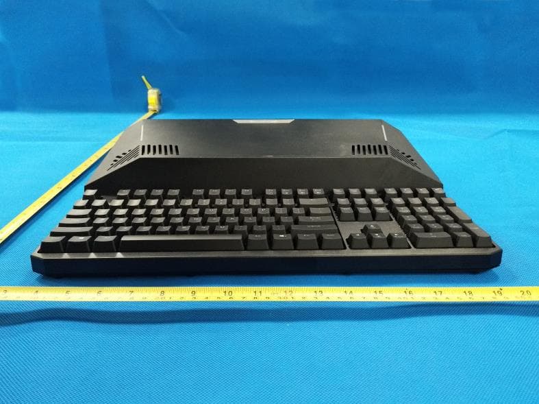
Click to zoom
Application Details
- Equipment Class
- DSS - Part 15 Spread Spectrum Transmitter
- Date of Grant
- Oct 04, 2021
- Application Purpose
- Original Equipment
- Date of Application
- Oct 04, 2021
- Equipment Note
- AIOJET
- Frequency Range
- 2402.00000000 - 2480.00000000
- Country
- China
Documents & Files
Document Text
Text extracted from the exhibit documents filed with the FCC. Open a document above to read the original.
Users Manual
P-F03005-0C US KPN21844 KM21E99000020N 105g 001 P-F03005-0C 1:1 001 210907 002 User Manual for AIOJET G1 Intelligent AIO Machine 1. Product List ..........................................................4 2. Description of Parts and Functions ..................4 3. Description of Parts and Functions—Intel NUC Element Version ...................................................6 4. Keyboard and RGB Functional Operation .......7 A Computer Mode 1. Start up and Enter Windows System ............8 2. Focusing/Short throw ..................................8 3. Connecting Earphone to Sound Box ...........9 4. WIFI & Bluetooth Connection Setting ...........9 5. Volume Adjustment/Sound Setting ..............10 B Projection Mode 1. HDMI Input Switch Mode ...........................11 2. Focusing/Short throw..................................11 3. Volume Adjustment ...................................11 Main Specifications .......................................12 Warranty Card and Quality Certificate ...........13 To avoid product damage, please pay attention to the following information before use for fear of eye injury, please do not look straight at the light source of projection from lens during equipment use。 do not put any object in front of the lens during equipment use。 please put the equipment on a steadily horizontal desktop to avoid damage from falling。 you might feel hot air from the vent during use, which is normal instead of design and production defect. for fear of impact on heat dissipation, do not put the equipment on quilt, blanket, and other textiles or cover it with other objects, which might cause the equipment to overheat, resulting in automatic turnoff or affecting its normal use。 do not place the equipment in a place with high temperature, excessive humidity, or in a place with dust and smoke to avoid contaminating the optics and prolong the life of the device。 please use the original adaptor and fittings. Do not use products that do not match。 the equipment is not waterproof. Please keep it dry。 if the equipment is accompanied by OS key, it will not be subject to refund after the key is activated。 ● Avoid direct exposure to strong light ● Do not block lens ● Place Steadily ● Head Dissipation ● Do Not Cover Product ● Placement ● Fittings ● Waterproofness ● Key please read the precautions above carefully. If the equipment is not used in accordance with the manual, the equipment damage or malfunction therefrom will not be repaired or repaired for free. As for fittings, you need to consult the after-sales service hotline to purchase the originals to guarantee the equipment works normally。 the equipment is grade-A. In living environment, it might cause radio jamming. In this case, the user might need to take practical measures。 ●After-sales precautions ● Electromagnetic Compatibility 3 . Device parts and function description-Intel Element Edition4 . Keyboard usage and RGB function operation ● Operating Method ● USB interface: two USB 3.0 interfaces and two USB 2.0 interfaces。 ● AUX interface: connect to earphone and sound box; connect to Bluetooth sound box with its Bluetooth when the computer system is working。 ● PC Switch Key: when the power is on, press this key to enable or disable PC mode, or adopt the turnoff method in Windows system。 ●HDMI and PC Mode Switch Key: when PC mode is switched to HDMI peripheral audio and visual equipment projection, press this key。 ●Light Source Switch Key: a. hold this key for 3s; or b. hold this key for 1s and wait 3min. Both methods can turn off LED light source。 ●When LED light source is off, press the light source switch key again, and the LED light source is on again。 Description of Functions of RGB Mechanical Keyboard I. 4 return switch keys: FN+ F1&FN+ F2&FN+ F3& FN+ F4 Return switching method: 1. FN + F1 = return 125 TIMES / SECOND 2. FN + F2 = return 250 TIMES / SECOND 3. FN + F3 = return 500 TIMES / SECOND 4. FN + F4 = return 1000 TIMES / SECOND(default) A. PC Mode I. Start up and enter Windows system (1)AIO machine power supply: connect the power adaptor to power cable socket of AIO machine, and insert the plug of the adaptor into the outlet. Start it immediately。 (2)Startup screen: SHOU brand boot screen appears after startup。 (3)PC mode startup: PC switch key is used to start the power. Press the key to run PC functions。 (4)Startup is complete when Windows screen appears, start any general operation on PC。 II. Focusing/Short throw (1)Focusing: when the play distance change of AIO machine makes the screen blurry, press the focusing key on the top right of the keyboard to bring it forward or backward. Move the lens till the screen gets clear。 (2)Auto-focusing: apply auto-focusing when the screen is blurry. Press the forward and backward focusing keys ,together on the top right to automatically focus. If the screen is still a little blurry after auto-focusing because of site factors, apply tuning in accordance with the focusing method in (1) above till the screen gets clear。 (3)Short throw: AIOJET G1 is the TI DLP optical system capable of Short Throw. The ratio of projection is 1:0.8, and the size of the projected screen is incomparably clear from laptop screen size to screen with more than 100 inches (screen brightness and resolution are affected to the brightness of the play environment. Please choose the proper placement location and a relatively darker place to play). G1 bears a play distance that is half of most long-focus projectors (projection ratio 1:1.2 or higher), which enhances the convenience of the play environment and enables watching everywhere. 1m can be used to project 60 inches, and 1.75m can be used to project 100 inches。 B. Projection Mode I. HDMI IN switch mode (1) HDMI interface: tablet PC, laptop, TV box, game console, and some medium- and high-end cell phones may be connected to the HDMI IN interface of the AIO machine via HDMI wire to realize projection on big screen。 (2)Signal Source Selection: A.Other equip…
Text truncated - open the document above for the full version.
Cover Letter(s)
CONFIDENTIALITY REQUEST for Certification Service in USA Federal Communication Commission Equipment Authorization Division, Application Processing Branch 7435 Oakland Mills Road Columbia, MD 21046 Date:<2021-9-28> Pursuant to Paragraphs §0.457 and 0.459 of the Commission’s Rules (47 C.F.R.) and Section §552(b)(4) of the Freedom of Information Act, we requests confidentiality for the following products: FCC ID Model name 2A3BL-G1 G1 For the product stated above, we request that the following information be held confidential; Exhibits Long-Term Confidentiality Short-Term Confidentiality Short-Term Confidentiality Days External Photos Internal Photos Block Diagram Schematics Test Setup Photos User’s Manual Parts List Tune Up Operational Descriptions The long-term confidentiality exhibits contain our trade secrets and proprietary information that could be of benefit to our competitors. The short-term confidentiality on the basis of ensuring that business sensitive information remains confidential until the actual marketing of our new device. If you have any questions, please feel free to contact me at the address shown below. Sincerely, Name/Title: Jianguo Liu/manager Company: YuHong Electronic (shenzhen) Co.,Ltd Address: 407,Floor 4,Building D,Youth Pioneer Park, Jianshe East Road,Tsinghua Community, Longhua Street, Longhua District, Shenzhen China Phone: 13424388340 Fax: N/A E-Mail: [email protected]
Cover Letter(s)
YuHong Electronic (shenzhen) Co.,Ltd 407,Floor 4,Building D,Youth Pioneer Park, Jianshe East Road,Tsinghua Community, Longhua Street, Longhua District, Shenzhen China Federal Communications Commission Authorization and Evaluation Division Equipment Authorization Branch 7435 Oakland Mills Road Columbia, MD 21046 2021-9-28 To whom it may concern: We, YuHong Electronic (shenzhen) Co.,Ltd the undersigned, hereby authorize Eurofins Product Service GmbH to act on our behalf in all matters relating to applications for equipment authorization FCC ID: 2A3BL-G1 including the signing of all documents related to these matters. Any and all acts carried out by Eurofins Product Service GmbH on our behalf shall have the same effect as acts of our own. We also hereby certify that no party to this application is subject to a denial of benefits, including FCC benefits, pursuant to Section 5301 of the Anti-Drug Abuse Act of 1988, 21 U.S.C. 862. Sincerely, Name/Title: Jianguo Liu/manager Company: YuHong Electronic (shenzhen) Co.,Ltd Address: 407,Floor 4,Building D,Youth Pioneer Park, Jianshe East Road,Tsinghua Community, Longhua Street, Longhua District, Shenzhen China Phone: 13424388340 Fax: N/A E-Mail: [email protected]
External Photos
FCC ID: 2A3BL-G1 External Photos of the EUT FCC ID: 2A3BL-G1
ID Label/Location Info
FCC ID: 2A3BL-G1 Label and Location Size: L: 3.0cm*W: 2.5cm Label and Location AIOJET Trade Mark: SHO-U Model No.: G1 FCC ID: 2A3BL-G1
Internal Photos
FCC ID: 2A3BL-G1 Internal Photos of the EUT FCC ID: 2A3BL-G1 Antenna 0 Antenna 1 FCC ID: 2A3BL-G1 FCC ID: 2A3BL-G1 FCC ID: 2A3BL-G1 FCC ID: 2A3BL-G1 FCC ID: 2A3BL-G1 FCC ID: 2A3BL-G1
RF Exposure Info
RF Exposure evaluation FCC ID: 2A3BL-G1 Exposure category: General population/uncontrolled environment EUT Type: Production Unit Device Type: Mobile Device 1. Reference According to §1.1307(b)(1), systems operating under the provisions of this section shall be operated in a manner that ensures that the public is not exposed to radio frequency energy level in excess of the Commission’s guidelines. According to §1.1310 and §2.1091 RF exposure is calculated. KDB447498 D01: Mobile and Portable Devices RF Exposure Procedures and Equipment Authorization Policies 2. Limit Limits for Maximum Permissible Exposure (MPE)/Controlled Exposure Frequency Range(MHz) Electric Field Strength(V/m) Magnetic Field Strength(A/m) Power Density (mW/cm²) Averaging Time (minute) Limits for Occupational/Controlled Exposure 0.3 – 3.0 3.0 – 30 30 – 300 300 – 1500 1500 – 100,000 614 1842/f 61.4 / / 1.63 4.89/f 0.163 / / (100) * (900/f 2 )* 1.0 f/300 5 6 6 6 6 6 Limits for Maximum Permissible Exposure (MPE)/Uncontrolled Exposure Frequency Range(MHz) Electric Field Strength(V/m) Magnetic Field Strength(A/m) Power Density (mW/cm²) Averaging Time (minute) Limits for Occupational/Controlled Exposure 0.3 – 3.0 3.0 – 30 30 – 300 300 – 1500 1500 – 100,000 614 824/f 27.5 / / 1.63 2.19/f 0.073 / / (100) * (180/f 2 )* 0.2 f/1500 1.0 30 30 30 30 30 F=frequency in MHz *=Plane-wave equivalent power density 3. MPE Calculation Method Predication of MPE limit at a given distance Equation from page 18 of OET Bulletin 65, Edition 97-01 S=PG/4πR² Where: S=power density P=power input to antenna G=power gain of the antenna in the direction of interest relative to an isotropic radiator R=distance to the center of radiation of the antenna 4. Antenna Information G1 can only use antennas certificated as follows provided by manufacturer; Antenna No. Model No. of antenna: Type of antenna: Gain of the antenna (Max.) Frequency range: Bluetooth / FPC Antenna -2.31dBi for 2402-2480MHz; 2.4G&5GWIFI / FPC Antenna -2.31dBi for 2412-2462MHz for ant 0 and ant 1 1.81dBi for 5150-5250MHz for ant 0 and ant 1 1.81dBi for 5725-5875MHz for ant 0 and ant 1 5. Conducted power Bluetooth Mode Channel Frequency Peak Conducted Output Power (dBm) GFSK 00 2402 6.37 39 2441 5.59 78 2480 5.63 Π/4DQPSK 00 2402 6.27 39 2441 5.92 78 2480 5.14 8DPSK 00 2402 6.48 39 2441 6.2 78 2480 5.38 GFSK BLE 00 2402 -4.92 19 2440 -5.17 39 2480 -5.74 [2.4GHz WLAN Antenna 0] Mode Channel Frequency Peak Conducted Output Power (dBm) IEEE 802.11b 1 2412 16.19 6 2437 16.37 11 2462 16.89 IEEE 802.11g 1 2412 15.86 6 2437 16.28 11 2462 16.85 IEEE 802.11n HT20 1 2412 13.57 6 2437 14.64 11 2462 13.81 IEEE 802.11n HT40 3 2422 12.88 6 2437 12.63 9 2452 12.92 [2.4GHz WLAN Antenna 1] Mode Channel Frequency Peak Conducted Output Power (dBm) IEEE 802.11b 1 2412 16.45 6 2437 16.32 11 2462 16.59 IEEE 802.11g 1 2412 16.13 6 2437 16.48 11 2462 16.22 IEEE 802.11n HT20 1 2412 13.89 6 2437 14.33 11 2462 14.12 IEEE 802.11n HT40 3 2422 12.47 6 2437 12.64 9 2452 12.71 [5.2GHz WLAN ] Mode Channel Frequency Average Conducted Output Power (dBm) Antenna 0 Antenna 1 802.11a 36 5180 16.55 16.23 40 5200 16.28 16.14 48 5240 16.62 16.55 802.11n(HT20) 36 5180 15.31 15.26 40 5200 15.58 15.83 48 5240 15.78 15.92 802.11n(HT40) 38 5190 16.76 16.44 46 5230 16.70 16.35 802.11ac(HT20) 36 5180 14.84 14.99 40 5200 15.27 15.14 48 5240 15.71 15.68 802.11ac(HT40) 38 5190 16.17 16.35 46 5230 16.72 16.49 802.11ac(HT80) 42 5210 16.24 16.42 [5.8GHz WLAN] Mode Channel Frequency Average Conducted Output Power (dBm) Antenna 0 Antenna 1 802.11a 149 5745 16.99 16.68 157 5785 16.48 16.27 165 5825 16.57 16.43 802.11n(HT20) 149 5745 16.87 16.59 157 5785 16.82 16.71 165 5825 16.59 16.44 802.11n(HT40) 151 5755 15.99 16.05 159 5795 16.09 16.18 802.11ac(HT20) 149 5745 16.72 16.66 157 5785 16.82 16.47 165 5825 16.23 16.54 802.11ac(HT40) 151 5755 16.57 16.36 159 5795 16.77 16.59 802.11ac(HT80) 155 5775 16.86 16.62 6. Manufacturing Tolerance <BT LE> GFSK (Peak) Channel Channel 0 Channel 19 Channel 39 Target (dBm) -4.0 -5.0 -5.0 Tolerance ±(dB) 1.0 1.0 1.0 <BT Classics> GFSK (Peak) Channel Channel 0 Channel 39 Channel 78 Target (dBm) 6.0 5.0 5.0 Tolerance ±(dB) 1.0 1.0 1.0 π/4DQPSK (Peak) Channel Channel 0 Channel 39 Channel 78 Target (dBm) 6.0 5.0 5.0 Tolerance ±(dB) 1.0 1.0 1.0 8DPSK (Peak) Channel Channel 0 Channel 39 Channel 78 Target (dBm) 6.0 6.0 5.0 Tolerance ±(dB) 1.0 1.0 1.0 [2.4GHz WLAN Antenna 0] IEEE 802.11b (Peak) Frequency (MHz) Antenna 0 Antenna 1 2412 2437 2462 2412 2437 2462 Target (dBm) 16.0 16.0 16.0 16.0 16.0 16.0 Tolerance ± (dB) 1.0 1.0 1.0 1.0 1.0 1.0 IEEE 802.11g(Peak) Frequency (MHz) Antenna 0 Antenna 1 2412 2437 2462 2412 2437 2462 Target (dBm) 16.0 16.0 16.0 16.0 16.0 16.0 Tolerance ± (dB) 1.0 1.0 1.0 1.0 1.0 1.0 IEEE 802.11n HT20 (Peak) Frequency (MHz) Antenna 0 Antenna 1 2412 2437 2462 2412 2437 2462 Target (dBm) 14.0 14.0 14.0 14.0 14.0 14.0 Tolerance ± (dB) 1.0 1.0 1.0 1.0 1.0 1.0 IEEE 802.11n HT40 (Peak) Frequency (MHz) Antenna 0 Antenna 1 2422 2437 2452 2422 2437 2452 Target (dBm) 13.0 13.0 13.0 13.0 13.0 13.0 Tolerance ± (dB) 1.0 1.0 1.0 1.0 1.0 1.0 5GHz WLAN Band 1 IEEE 802.11a (Average) Frequency (MHz) Antenna 0 Antenna 1 5180 5200 5240 5180 5200 5240 Target (dBm) 16.0 16.0 16.0 16.0 16.0 16.0 Tolerance ± (dB) 1.0 1.0 1.0 1.0 1.0 1.0 IEEE 802.11n HT20 (Average) Frequency (MHz) Antenna 0 Antenna 1 5180 5200 5240 5180 5200 5240 Target (dBm) 15.0 15.0 15.0 15.0 15.0 15.0 Tolerance ± (dB) 1.0 1.0 1.0 1.0 1.0 1.0 IEEE 802.11ac VHT20 (Average) Frequency (MHz) Antenna 0 Antenna 1 5180 5200 5240 5180 5200 5240 Target (dBm) 15.0 15.0 15.0 15.0 15.0 15.0 Tolerance ± (dB) 1.0 1.0 1.0 1.0 1.0 1.0 IEEE 802.11n HT40 (Average) Frequency (MHz) Antenna 0 Antenna 1 5190 5230 5190 5230 Target (dBm) 16.0 16.0 16.0 16.0 Tolerance ± (dB) 1.0 1.0 1.0 1.0 IEEE 802.11ac VHT40 (Average) Frequency (MHz) Antenna 0 Antenna 1 5190 5230 5190 5230 Target (dBm) 16.0 16.0 16.0 16.0 Tolerance ± (dB) 1.0 1.0 1.0 1.0 IEEE 802.11ac VHT80 (Average) Frequen…
Text truncated - open the document above for the full version.
Test Report
Shenzhen GUOREN Certification Technology Service Co., Ltd. 101#, Building K & Building T, The Second Industrial Zone, Jiazitang Community, Fenghuang Street, Guangming District, Shenzhen, China FCC PART 15 SUBPART C TEST REPORT FCC PART 15.247 Report Reference No. ..................... : FCC ID. ............................................ : GRCTR210902004-01 2A3BL-G1 Compiled by ( position+printed name+signature) .. : Testing Engineer Jimmy Wang Supervised by ( position+printed name+signature) .. : Project Engineer Kelley Zhang Approved by ( position+printed name+signature) .. : Manager Sam Wang Date of issue ..................................... : Sep. 14, 2021 Testing Laboratory Name .............. : Shenzhen GUOREN Certification Technology Service Co., Ltd. Address ............................................ : 101#, Building K & Building T, The Second Industrial Zone, Jiazitang Community, Fenghuang Street, Guangming District, Shenzhen, China Applicant’s name ............................ : YuHong Electronic (shenzhen) Co.,Ltd Address ............................................ : 407, Floor 4, Building D, Youth Pioneer Park, Jianshe East Road, Tsinghua Community, Longhua Street, Longhua District, Shenzhen Test specification ...........................: Standard ........................................... : FCC Part 15.247 Shenzhen GUOREN Certification Technology Service Co., Ltd. All rights reserved. This publication may be reproduced in whole or in part for non-commercial purposes as long as the Shenzhen GUOREN Certification Technology Service Co., Ltd. is acknowledged as copyright owner and source of the material. Shenzhen GUOREN Certification Technology Service Co., Ltd. takes no responsibility for and will not assume liability for damages resulting from the reader's interpretation of the reproduced material due to its placement and context. Test item description .....................: AIOJET Trade Mark ....................................... : SHO-U Manufacturer .................................... : YuHong Electronic (shenzhen) Co.,Ltd Model/Type reference....................... : G1 Listed Models .................................. : N/A Modulation ....................................... : GFSK, Π/4DQPSK,8DPSK Frequency .......................................... From 2402MHz to 2480MHz Rating ............................................... : DC 19.0V From external circuit Result................................................ : PASS Report No.: GRCTR210902004-01 Page 2 of 53 T E S T R E P O R T Equipment under Test : AIOJET Model /Type : G1 Listed Models : N/A Applicant : YuHong Electronic (shenzhen) Co.,Ltd Address : 407, Floor 4, Building D, Youth Pioneer Park, Jianshe East Road, Tsinghua Community, Longhua Street, Longhua District, Shenzhen Manufacturer : YuHong Electronic (shenzhen) Co.,Ltd Address : 407, Floor 4, Building D, Youth Pioneer Park, Jianshe East Road, Tsinghua Community, Longhua Street, Longhua District, Shenzhen Test Result: PASS The test report merely corresponds to the test sample. It is not permitted to copy extracts of these test result without the written permission of the test laboratory. Report No.: GRCTR210902004-01 Page 3 of 53 Contents 1 T E S T S T A N D A R D S ........................................................................ 4 2 S U M M A R Y ................................................................................... 5 2.1 General Remarks .......................................................................................................................................... 5 2.2 Product Description ..................................................................................................................................... 5 2.3 Equipment Under Test ................................................................................................................................. 5 2.4 Short description of the Equipment under Test (EUT) ............................................................................. 5 2.5 EUT operation mode .................................................................................................................................... 5 2.6 Block Diagram of Test Setup ...................................................................................................................... 6 2.7 Related Submittal(s) / Grant (s) ................................................................................................................... 6 2.8 Modifications ................................................................................................................................................ 6 3 T ES T EN V I R O N M E N T .................................................................... 7 3.1 Address of the test laboratory .................................................................................................................... 7 3.2 Test Facility ................................................................................................................................................... 7 3.3 Environmental conditions ........................................................................................................................... 7 3.4 Summary of measurement results ............................................................................................................. 8 3.5 Statement of the measurement uncertainty .............................................................................................. 8 3.6 Equipments Used during the Test .............................................................................................................. 9 4 T E S T C O N D I T I O N S A N D R E S U L T S .................................................. 10 4.1 AC Power Conducted Emission ................................................................................................................ 10 4.2 Radiated Emission ..............................…
Text truncated - open the document above for the full version.
Test Report
Report No.: GRCTR210902004-01 Page 38 of 53 Band-edge Measurements for RF Conducted Emissions: GFSK Left Band edge hoping off Right Band edge hoping off Left Band edge hoping on Right Band edge hoping on Report No.: GRCTR210902004-01 Page 39 of 53 π/4DQPSK Left Band edge hoping off Right Band edge hoping off Left Band edge hoping on Right Band edge hoping on Report No.: GRCTR210902004-01 Page 40 of 53 8DPSK Left Band edge hoping off Right Band edge hoping off Left Band edge hoping on Right Band edge hoping on Report No.: GRCTR210902004-01 Page 41 of 53 4.9 Pseudorandom Frequency Hopping Sequence TEST APPLICABLE For 47 CFR Part 15C section 15.247 (a) (1) requirement: Frequency hopping systems shall have hopping channel carrier frequencies separated by a minimum of 25 kHz or the 20 dB bandwidth of the hop-ping channel, whichever is greater. Alternatively, frequency hopping systems operating in the 2400–2483.5 MHz band may have hopping channel carrier frequencies that are separated by 25 kHz or two-thirds of the 20 dB bandwidth of the hopping channel, whichever is greater, provided the systems operate with an output power no greater than 125 mW. The system shall hop to channel frequencies that are selected at the system hopping rate from a pseudo randomly ordered list of hopping frequencies. Each frequency must be used equally on the average by each transmitter. The system receivers shall have input bandwidths that match the hop-ping channel bandwidths of their corresponding transmitters and shall shift frequencies in synchronization with the transmitted signals. EUT Pseudorandom Frequency Hopping Sequence Requirement The pseudorandom frequency hopping sequence may be generated in a nice-stage shift register whose 5 th and 9 th stage outputs are added in a modulo-two addition stage. And the result is fed back to the input of the first stage. The sequence begins with the first one of 9 consecutive ones, for example: the shift register is initialized with nine ones. ● Number of shift register stages:9 ● Length of pseudo-random sequence:29-1=511 bits ● Longest sequence of zeros:8(non-inverted signal) An example of pseudorandom frequency hopping sequence as follows: Each frequency used equally one the average by each transmitter. The system receiver have input bandwidths that match the hopping channel bandwidths of their corresponding transmitter and shift frequencies in synchronization with the transmitted signals. Report No.: GRCTR210902004-01 Page 42 of 53 4.10 Antenna Requirement Standard Applicable For intentional device, according to FCC 47 CFR Section 15.203, an intentional radiator shall be designed to ensure that no antenna other than that furnished by the responsible party shall be used with the device. And according to FCC 47 CFR Section 15.247 (c), if transmitting antennas of directional gain greater than 6dBi are used, the power shall be reduced by the amount in dB that the directional gain of the antenna exceeds 6dBi. Refer to statement below for compliance The manufacturer may design the unit so that the user can replace a broken antenna, but the use of a standard antenna jack or electrical connector is prohibited. Further, this requirement does not apply to intentional radiators that must be professionally installed. Antenna Connected Construction The maximum gain of antenna was -2.31 dBi. Remark:The antenna gain is provided by the customer , if the data provided by the customer is not accurate, Shenzhen GUOREN Certification Technology Service Co., Ltd. does not assume any responsibility. Report No.: GRCTR210902004-01 Page 43 of 53 5 T e s t S e t u p P h o t o s o f t h e E U T Report No.: GRCTR210902004-01 Page 44 of 53 6 P h o t o s o f t h e E U T Report No.: GRCTR210902004-01 Page 45 of 53 Report No.: GRCTR210902004-01 Page 46 of 53 Report No.: GRCTR210902004-01 Page 47 of 53 Report No.: GRCTR210902004-01 Page 48 of 53 Report No.: GRCTR210902004-01 Page 49 of 53 Report No.: GRCTR210902004-01 Page 50 of 53 Report No.: GRCTR210902004-01 Page 51 of 53 Report No.: GRCTR210902004-01 Page 52 of 53 Report No.: GRCTR210902004-01 Page 53 of 53 ********************** End of Report **********************
Test Setup Photos
FCC ID: 2A3BL-G1 Test Setup Photos of the EUT Test Setup Photo(s) of Radiated Emissions Measurement Fig. 1 Fig. 2 FCC ID: 2A3BL-G1 Test Setup Photo of Line Conducted Emissions Measurement
Contact Information
Applicant
Jianguo Liu(Manager)
Test Firm
Shenzhen GUOREN Certification Technology Service CSam Wang
[email protected]+86 755 23408306
Technical Specifications
| # | Rule Parts | Frequency Range | Power Output |
|---|---|---|---|
| 1 | 15C | 2.40 GHz - 2.48 GHz | 4.40 mW |