2A3FT-NBP12N-Series Digital Wireless System Bodypack Transmitter
DPA Microphones A/S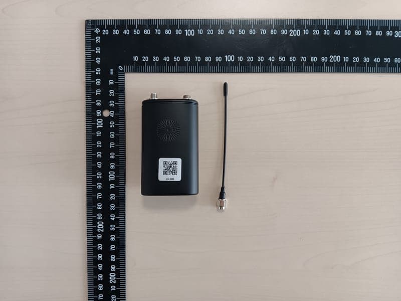
Click to zoom
Application Details
- Equipment Class
- DWM - Part 15 Wireless Microphone
- Date of Grant
- Mar 27, 2026
- Application Purpose
- Original Equipment
- Equipment Note
- N-Series Digital Wireless System Bodypack Transmitter
- Frequency Range
- 614.20000000 - 615.80000000
- Company
- DPA Microphones A/S
- Country
- Denmark
Documents & Files
Document Text
Text extracted from the exhibit documents filed with the FCC. Open a document above to read the original.
Users Manual
Version: March 10, 2026 1 N-Series Digital Wireless Microphone System User Guide Version: March 10, 2026 2 Introduction ------------------------------------------------------------------------------------------------------------------ 6 Quick start guide------------------------------------------------------------------------------------------------------------- 7 Getting started -------------------------------------------------------------------------------------------------------------- 14 Tuning the system ------------------------------------------------------------------------------------------------------ 14 Performing a QUICK SETUP ---------------------------------------------------------------------------------------- 15 Performing manual set up of group and channels ----------------------------------------------------------- 17 Performing manual set up of frequency ----------------------------------------------------------------------- 18 Synchronizing a Transmitter ------------------------------------------------------------------------------------------ 18 N-DR1 Digital Dual Channel Receiver ---------------------------------------------------------------------------------- 19 Included in the box ----------------------------------------------------------------------------------------------------- 19 Hardware overview ----------------------------------------------------------------------------------------------------- 19 Installation ---------------------------------------------------------------------------------------------------------------- 21 Antenna cables ---------------------------------------------------------------------------------------------------------- 22 Operation ----------------------------------------------------------------------------------------------------------------- 23 Main and detailed screens ----------------------------------------------------------------------------------------- 23 Menu system ------------------------------------------------------------------------------------------------------------- 24 Main menu ------------------------------------------------------------------------------------------------------------ 26 Functions and settings ---------------------------------------------------------------------------------------------- 26 Headphone mode ---------------------------------------------------------------------------------------------------- 26 Display brightness --------------------------------------------------------------------------------------------------- 27 Primary ----------------------------------------------------------------------------------------------------------------- 32 IP address -------------------------------------------------------------------------------------------------------------- 33 Subnet ------------------------------------------------------------------------------------------------------------------ 33 Gateway ---------------------------------------------------------------------------------------------------------------- 33 MAC address ---------------------------------------------------------------------------------------------------------- 33 Date and time --------------------------------------------------------------------------------------------------------- 34 Date --------------------------------------------------------------------------------------------------------------------- 34 Time --------------------------------------------------------------------------------------------------------------------- 34 Transmitter Firmware update ------------------------------------------------------------------------------------ 34 Factory restore ------------------------------------------------------------------------------------------------------- 34 Device information -------------------------------------------------------------------------------------------------- 34 Channel Menu ----------------------------------------------------------------------------------------------------------- 35 Functions and settings ------------------------------------------------------------------------------------------------- 35 QUICK SETUP ---------------------------------------------------------------------------------------------------------- 35 Channel name -------------------------------------------------------------------------------------------------------- 35 Version: March 10, 2026 3 Radio -------------------------------------------------------------------------------------------------------------------- 36 Encryption ------------------------------------------------------------------------------------------------------------- 36 Keep TX settings ------------------------------------------------------------------------------------------------------ 37 Transmitter settings ------------------------------------------------------------------------------------------------- 37 Audio low-cut --------------------------------------------------------------------------------------------------------- 37 Function key ----------------------------------------------------------------------------------------------------------- 38 Menu lock -------------------------------------------------------------------------------------------------------------- 38 RF Power --------------------------------------------------------------------------------------------------------------- 38 Battery Type ----------------------------------------------------------------------------------------------------------- 39 Battery status --------------------------------------------------------------------------------------------------------- 39 Information (Tx) ------------------------------------------------------------------------------------------------------ 39 Receiver ---------------------------------------------------------------------------------------------------------------- 39 Mute ---------------------------------------------------------------------------…
Text truncated - open the document above for the full version.
External Photos
Annex A101 - Photographs No. 1-1312-25-01-03_TR1-A101-R01 February 10, 2026 DescriptionExternal photos of EUT This document is electronically signed and valid without handwritten signature. Public keys for verifcation of the electronic signatures can be requested at the testing laboratory. Hans-Joachim Wolsdorfer Lab Manager Regulatory Services Radio authorized by cetecom advanced GmbH Untertuerkheimer Str. 6-10, 66117 Saarbruecken Document No. 1-1312-25-01-03_TR1-A101-R01 Page 1 of 6 Photo 1 Photo 2 cetecom advanced GmbH Untertuerkheimer Str. 6-10, 66117 Saarbruecken Document No. 1-1312-25-01-03_TR1-A101-R01 Page 2 of 6 Photo 3 Photo 4 cetecom advanced GmbH Untertuerkheimer Str. 6-10, 66117 Saarbruecken Document No. 1-1312-25-01-03_TR1-A101-R01 Page 3 of 6 Photo 5 Photo 6 cetecom advanced GmbH Untertuerkheimer Str. 6-10, 66117 Saarbruecken Document No. 1-1312-25-01-03_TR1-A101-R01 Page 4 of 6 Photo 7 cetecom advanced GmbH Untertuerkheimer Str. 6-10, 66117 Saarbruecken Document No. 1-1312-25-01-03_TR1-A101-R01 Page 5 of 6 Document History End of document ReleaseApplied changesRelease date R01initial releaseFebruary 10, 2026 cetecom advanced GmbH Untertuerkheimer Str. 6-10, 66117 Saarbruecken Document No. 1-1312-25-01-03_TR1-A101-R01 Page 6 of 6
ID Label/Location Info
N-Series Label specifications Version 14. N-DR1, Dual digital receiver Label requirement Marking Requirement Model number CE Serial number CE Manufacturer address CE CE (RED, EMC, LVD) CE & UK CA Minimum height 5 mm WEEE symbol minimum height 7 mm North America (FCC / ISED) IEC 60417 – 5957 For indoor use only Minimum height 5 mm 470MHz – 870MHz Frequency range. This may vary depending on the region. Control LAN MAC: XX:XX:XX:XX:XX:XX Control LAN MAC address Dante LAN MAC: XX:XX:XX:XX:XX:XX Dante MAC address QR-code Landing page Country of Origin Made in China Label example Two labels will be used. The main label (Label A) with all the standard markings on and the serial number label (Label B) with type number, serial number, receiver frequency range and the MAC addresses of the network adaptors. (Control LAN and Dante). The label will be placed on the bottom of the unit just under the main power connector. Label B will be placed on label A within the dedicated area. Label A Premade label equal to all variations of N-DR1 Specifications: Size 50 mm x 50 mm Background color Black Text color White Material/type Paper, Matt film, Permanent adhesive Label B Unique label for each device and is therefore printed on site in production. Specifications: Size 33 mm x 10 mm Background color Black Text color White N-HH1-SL1, Handheld transmitter N-BP1 (-03, -90) Body pack transmitter Label requirement Marking Requirement Model number CE Serial number CE Manufacturer address CE CE (RED, EMC, LVD) For N-HH1-SL1: FCC ID: 2A3FT-NHH1SL1 FCC ID: 2A3FT-NHH1SL12 HVIN: N-HH1-SL1 IC: 28129-NHH1SL1 For N-BP1: FCC ID: 2A3FT-NBP1 FCC ID: 2A3FT-NBP12 HVIN: N-BP1 IC: 28129-NBP1 North America (FCC / ISED) 470MHz – 870MHz Frequency range. This may vary depending on the region. QR-code Product landing page Country of Origin Made in China Only for N-HH1 Label A: Icon telling the user to read the user’s guide regarding changing the battery. To be clarified PSE, MIC (Japan) Bodypack transmitter label (N-BP1-ZZ-R) Three labels will be used. Label A: Including non-device specific information e.g. Icons, ID’s, country of origin and URL. Label B: Model name, serial number frequency ranges etc. Label C: Indication to the user regarding battery change. Label A Premade label equal to all variations of N-BP1 Specifications: Size 30 mm x 36 mm Background color Black Text color White Material/type Paper, Matt film, Permanent adhesive Label A is placed on the inside of the lid within the area shown below. Label B Unique label for each device and is therefore printed on site in production. Specifications: Size 33 mm x 5 mm Background color Black Text color White See Appendix 1 regarding product number (P/N), Frequency (Freq) and serial number (S/N) specification. Please note that the frequency information is dependent on the area code. See appendix 1 Frequency Indication Label B is placed on the inside of the lid at the bottom within the area shown below. Label C Placed on the hinge between the battery terminals. E-Label Introduced in firmware version 1.6 to accommodate for the new FCC ID numbers. The FCC and ISED information can be read via the device menu system under REGULTORY. The E-Label will only be shown in the B versions of N-BP1 (North America) (N-BP1-90-B and N-NP1- 06-B). Path: MENU -> REGULATORY 1 Press Menu -> -> 2 Navigate down to REGULATORY 3 Press Menu to enter the regulatory menu point 4 and Use the arrow keys to switch between FCC and ISED information Handheld transmitter label (N-HH1-SL1-R) Three labels will be used. Label A: Including non-device specific information e.g. Icons, ID’s, country of origin and URL. Label B: Model name, serial number frequency ranges etc. Label C: Indication to the user regarding battery change. Label A Premade label equal to all variations of N-HH1-SL1 Specifications: Size (W x H) 60 mm x 13 mm Background color Black Text color White Material/type Paper, Matt film, Permanent adhesive Label A will be placed in the battery compartment under the AA battery tray. Label B Unique label for each device and is therefore printed on site in production. Specifications: Size 33 mm x 5 mm Background color Black Text color White See Appendix 1 regarding product number (P/N), Frequency (Freq) and serial number (S/N) specification. Please note that the frequency information is dependent on the area code. See appendix 1 Frequency Indication Label B is placed on the plastic outside the battery tray just above the IR window in the area indicated below. Label C Please inside the battery tray. E-Label Introduced in firmware version 1.6 to accommodate for the new FCC ID numbers. The FCC and ISED information can be read via the device menu system under REGULTORY. The E-Label will only be shown in the B versions of N-HH1-SL1 (North America) (N-HH1-SL1-B). Path: MENU -> REGULATORY 1 Press Menu -> -> 2 Navigate down to REGULATORY 3 Press Menu to enter the regulatory menu point 4 and Use the arrow keys to switch between FCC and ISED information Appendix 1 Part number specification (P/N) Format: N-XTY-ZZ-R System Number of channels Type Version Option Region Description N -X T Y -ZZ -R -X: (Only for Receivers) - D: Dual channels - Q: Quad Channels T: - R: Receiver - BP: Body Pack - HH: Handheld Y: - Version number -ZZ: - No option is present if blank - -AO: Analog Option - -90: MicroLock audio connetor - -03: Lemo audio connector - -SL1: Microphone cartridge interface -R: - Not region dependent if blank - A: Europa - B: North America - C1: Japan, frequency range 1 - C2: Japan, frequency range 2 - D: China Frequency Indication The frequency indication on the transmitters is dependent on the region. A (Europe) 470 – 870 MHz B (North America) 470 – 608 MHz, 614 – 616 MHz, 653 – 663 MHz C1 (Japan freq. range 1) 470 – 714 MHz, 806 – 810 MHz C2 (Japan freq. range 2) 806 – 810 MHz D (China) 470 – 698 MHz Serial number specification The serial number is constructed by a 2 characters long product type identifier followed…
Text truncated - open the document above for the full version.
Internal Photos
Annex A102 - Photographs No. 1-1312-25-01-03_TR1-A102-R01 February 10, 2026 DescriptionInternal photos of EUT This document is electronically signed and valid without handwritten signature. Public keys for verifcation of the electronic signatures can be requested at the testing laboratory. Hans-Joachim Wolsdorfer Lab Manager Regulatory Services Radio authorized by cetecom advanced GmbH Untertuerkheimer Str. 6-10, 66117 Saarbruecken Document No. 1-1312-25-01-03_TR1-A102-R01 Page 1 of 4 Photo 1 Photo 2 cetecom advanced GmbH Untertuerkheimer Str. 6-10, 66117 Saarbruecken Document No. 1-1312-25-01-03_TR1-A102-R01 Page 2 of 4 Photo 3 cetecom advanced GmbH Untertuerkheimer Str. 6-10, 66117 Saarbruecken Document No. 1-1312-25-01-03_TR1-A102-R01 Page 3 of 4 Document History End of document ReleaseApplied changesRelease date R01initial releaseFebruary 10, 2026 cetecom advanced GmbH Untertuerkheimer Str. 6-10, 66117 Saarbruecken Document No. 1-1312-25-01-03_TR1-A102-R01 Page 4 of 4
RF Exposure Info
© cetecom advanced GmbH Page 1 of 28 TEST REPORT Test Report No.: 1-1312-25-01-07_TR1-R01 Testing Laboratory Applicant cetecom advanced GmbH Untertuerkheimer Strasse 6 – 10 66117 Saarbruecken / Germany Phone: + 49 681 5 98 - 0 Fax: + 49 681 5 98 - 9075 Internet: https://cetecomadvanced.com e-mail: [email protected] Accredited Testing Laboratory: The testing laboratory (area of testing) is accredited according to DIN EN ISO/IEC 17025 (2018-03) by the Deutsche Akkreditierungsstelle GmbH (DAkkS). The accreditation is valid for the scope of testing procedures as stated in the accreditation certificate with the registration number: D-PL-12047-01-00. ISED Testing Laboratory Recognized Listing Number: DE0001 FCC designation number: DE0002 AEB srl Via Brodolini, 8 40056 Crespellano (Bologna)/ITALY Phone: +39 0 51 96 98 70 Contact: Andrea Molinari e-mail: [email protected] Phone: Tel +39 051 969870 - Int.112 Fax: +39 051 969725 Manufacturer AEB srl Via Brodolini, 8 40056 Crespellano (Bologna)/ITALY Test Standards IEC/IEEE 62209-1528-2020 Measurement procedure for the assessment of specific absorption rate of human exposure to radio frequency fields from hand-held and body-mounted wireless communication devices – Part 1528: Human models, instrumentation, and procedures (Frequency range of 4 MHz to 10 GHz) RSS-102 Issue 6 Radio Frequency Exposure Compliance of Radiocommunication Apparatus (All Frequency Bands) For further applied test standards please refer to section 3 of this test report. Test Item Kind of test item: Bodypack Transmitter Device type: portable device Model name: N-BP1 S/N serial number: CA000000 FCC-ID: 2A3FT-NBP1 / 2A3FT-NBP12 ISED Number: 28129-NBP1 Product Marketing Name (PMN): N-BP1 Hardware Version Identification No. (HVIN): N-BP1 Hardware status: 1 Software status: 1.5 b 1362 Firmware status: 1.6 Type of modulation: 4FSK Frequency: 614 MHz – 616 MHz | 657 MHz – 663 MHz Antenna: external antenna Battery option: 2.4 V to 4.2 V DC, by AA battery Test sample status: identical prototype Exposure category: general population / uncontrolled environment This test report is electronically signed and valid without handwritten signature. For verification of the electronic signatures, the public keys can be requested at the testing laboratory. Test Report authorised: Test performed: Alexander Hnatovskiy Obada Abo Oun Coordinator Area Testing Manager Radio Labs Regulatory Services Radio Test report no.: 1-1312-25-01-07_TR1-R01 © cetecom advanced GmbH Page 2 of 28 1 Table of contents 1 Table of contents ............................................................................................................................................ 2 2 General information ....................................................................................................................................... 3 2.1 Notes and disclaimer .......................................................................................................................... 3 2.2 Application details ............................................................................................................................... 3 2.3 Statement of compliance .................................................................................................................... 3 3 Test standards/ procedures references ....................................................................................................... 4 3.1 RF exposure limits .............................................................................................................................. 4 4 Reporting statements of conformity – decision rule .................................................................................. 5 5 Summary of Measurement Results .............................................................................................................. 5 6 Test Environment ........................................................................................................................................... 5 7 Test Set-up ...................................................................................................................................................... 6 7.1 Measurement system .......................................................................................................................... 6 7.1.1 System Description ..................................................................................................................... 6 7.1.2 Test environment ........................................................................................................................ 7 7.1.3 Probe description ........................................................................................................................ 7 7.1.4 Phantom description ................................................................................................................... 8 7.1.5 Device holder description ........................................................................................................... 8 7.1.6 Scanning procedure .................................................................................................................... 9 7.1.7 Spatial Peak SAR Evaluation ................................................................................................... 13 7.1.8 Data Storage and Evaluation .................................................................................................... 15 7.1.9 Tissue simulating liquids: dielectric properties ......................................................................... 17 7.1.10 Tissue simulating liquids: parameters ...................................................................................... 17 7.1.11 Measurement uncertainty evaluation for SAR test ................................................................... 18 7.1.12 Measurement uncertainty evaluation for System Check ......................…
Text truncated - open the document above for the full version.
RF Exposure Info
Page 1 of 29 Annex D Appendix No.: 1-1312-25-01-07_TR1-A201-R01 Testing Laboratory cetecom advanced GmbH Untertuerkheimer Strasse 6 – 10 66117 Saarbruecken/Germany Phone: + 49 681 5 98 - 0 Fax: + 49 681 5 98 - 9075 Internet: https://www.cetecomadvanced.com e-mail: [email protected] Accredited Test Laboratory: The testing laboratory (area of testing) is accredited according to DIN EN ISO/IEC 17025 (2018-03) by the Deutsche Akkreditierungsstelle GmbH (DAkkS) The accreditation is valid for the scope of testing procedures as stated in the accreditation certificate starting with the registration number: D-PL-12047-01-00. Appendix with Calibration data, Phantom certificate and system check information 2012-01-16 Test report no.: 1-1312-25-01-07_TR1-A201-R01 Page 2 of 29 1 Table of contents 1 Table of contents ....................................................................................................................................... 2 2 Calibration report “Probe EX3DV4” – SN: 3944 ..................................................................................... 3 3 Calibration report “600 MHz System validation dipole” ...................................................................... 13 4 Calibration certificate of Data Acquisition Unit (DAE) – SN: 477 ....................................................... 21 5 Certificate of “SAM Twin Phantom V8.0’’ ............................................................................................. 22 6 Certificate of “ELI Phantom V8.0’’ ......................................................................................................... 23 7 Application Note System Performance Check ..................................................................................... 24 7.1 Purpose of system performance check ..................................................................................... 24 7.2 System Performance check procedure ...................................................................................... 24 7.3 Uncertainty Budget ...................................................................................................................... 25 7.4 Power set-up for validation ......................................................................................................... 28 7.5 Laboratory reflection ................................................................................................................... 29 7.6 Additional system checks ........................................................................................................... 29 Test report no.: 1-1312-25-01-07_TR1-A201-R01 Page 3 of 29 2 Calibration report “Probe EX3DV4” – SN: 3944 Test report no.: 1-1312-25-01-07_TR1-A201-R01 Page 4 of 29 Test report no.: 1-1312-25-01-07_TR1-A201-R01 Page 5 of 29 Test report no.: 1-1312-25-01-07_TR1-A201-R01 Page 6 of 29 Test report no.: 1-1312-25-01-07_TR1-A201-R01 Page 7 of 29 Test report no.: 1-1312-25-01-07_TR1-A201-R01 Page 8 of 29 Test report no.: 1-1312-25-01-07_TR1-A201-R01 Page 9 of 29 Test report no.: 1-1312-25-01-07_TR1-A201-R01 Page 10 of 29 Test report no.: 1-1312-25-01-07_TR1-A201-R01 Page 11 of 29 Test report no.: 1-1312-25-01-07_TR1-A201-R01 Page 12 of 29 Test report no.: 1-1312-25-01-07_TR1-A201-R01 Page 13 of 29 3 Calibration report “600 MHz System validation dipole” Test report no.: 1-1312-25-01-07_TR1-A201-R01 Page 14 of 29 Test report no.: 1-1312-25-01-07_TR1-A201-R01 Page 15 of 29 Test report no.: 1-1312-25-01-07_TR1-A201-R01 Page 16 of 29 Test report no.: 1-1312-25-01-07_TR1-A201-R01 Page 17 of 29 Test report no.: 1-1312-25-01-07_TR1-A201-R01 Page 18 of 29 Test report no.: 1-1312-25-01-07_TR1-A201-R01 Page 19 of 29 Antenna Parameters with Head TSL From cal. data Measured 2024-06-21 Impedance; transformed to feed point 58.6Ω +1.5jΩ 57.3Ω +2.2jΩ Return Loss -21.9dB -23.0dB Test report no.: 1-1312-25-01-07_TR1-A201-R01 Page 20 of 29 Antenna Parameters with Head TSL From cal. data Measured 2025-10-30 Impedance; transformed to feed point 58.6Ω +1.5jΩ 58.3Ω +2.4jΩ Return Loss -21.9dB -22.0dB Test report no.: 1-1312-25-01-07_TR1-A201-R01 Page 21 of 29 4 Calibration certificate of Data Acquisition Unit (DAE) – SN: 477 Test report no.: 1-1312-25-01-07_TR1-A201-R01 Page 22 of 29 5 Certificate of “SAM Twin Phantom V8.0’’ Test report no.: 1-1312-25-01-07_TR1-A201-R01 Page 23 of 29 6 Certificate of “ELI Phantom V8.0’’ Test report no.: 1-1312-25-01-07_TR1-A201-R01 Page 24 of 29 7 Application Note System Performance Check 7.1 Purpose of system performance check The system performance check verifies that the system operates within its specifications. System and operator errors can be detected and corrected. It is recommended that the system performance check is performed prior to any usage of the system in order to guarantee reproducible results. The measurement of the Specific Absorption Rate (SAR) is a complicated task and the result depends on the proper functioning of many components and the correct settings of many parameters. Faulty results due to drift, failures or incorrect parameters might not be recognized, since they often look similar in distribution to the correct ones. The Dosimetric Assessment System DASY incorporates a system performance check procedure to test the proper functioning of the system. The system performance check uses normal SAR measurements in a simplified setup (the flat section of the SAM Twin Phantom) with a well characterized source (a matched dipole at a specified distance). This setup was selected to give a high sensitivity to all parameters that might fail or vary over time (e.g., probe, liquid parameters, and software settings) and a low sensitivity to external effects inherent in the system (e.g., positioning uncertainty of the device holder). The system performance check does not replace the calibration of the components. The accuracy of the system performance check is not sufficient for calibration purposes. It is possible to calcu…
Text truncated - open the document above for the full version.
RF Exposure Info
Page 1 of 6 Annex C Photo documentation Appendix No.: 1-1312-25-01-07_TR1-A101-R01 Testing Laboratory cetecom advanced GmbH Untertuerkheimer Strasse 6 – 10 66117 Saarbruecken/Germany Phone: + 49 681 5 98 - 0 Fax: + 49 681 5 98 - 9075 Internet: https://www.cetecomadvanced.com e-mail: [email protected] Appendix no.: 1-1312-25-01-07_TR1-A101-R01 Page 2 of 6 Photo 1: Measurement System DASY Photo 2: DUT - front view Appendix no.: 1-1312-25-01-07_TR1-A101-R01 Page 3 of 6 Photo 3: DUT - front view (opened) Photo 4: DUT - left view Appendix no.: 1-1312-25-01-07_TR1-A101-R01 Page 4 of 6 Photo 5: DUT - back view Photo 6: Test position front side without any distance Appendix no.: 1-1312-25-01-07_TR1-A101-R01 Page 5 of 6 Photo 7: Test position back side without any distance Photo 8: Test position left side without any distance Appendix no.: 1-1312-25-01-07_TR1-A101-R01 Page 6 of 6 Photo 9: Test position right side without any distance Photo 10: Test position bottom side without any distance
Test Report
TEST REPORT Test report no.: 1-1312-25-01-05_TR1-R03 Testing laboratory Applicant cetecom advanced GmbH Untertuerkheimer Strasse 6 – 10 66117 Saarbruecken / Germany Phone: + 49 681 5 98 - 0 Fax: + 49 681 5 98 - 9075 Internet: https://cetecomadvanced.com e-mail: [email protected] Accredited Testing Laboratory: The testing laboratory (area of testing) is accredited according to DIN EN ISO/IEC 17025 (2018-03) by the Deutsche Akkreditierungsstelle GmbH (DAkkS). The accreditation is valid for the scope of testing procedures as stated in the accreditation certificate with the registration number: D-PL-12047-01-00. ISED Testing Laboratory Recognized Listing Number: DE0001 FCC designation number: DE0002 DPA Microphones A/S Kokkedal Industripark 10 2980 Kokkedal / DENMARK Phone: +45 29 31 08 41 Contact: Niels Schou Frederiksen e-mail: [email protected] Manufacturer Pasgao Electronics Co., Ltd. V1 2 nd District, Industrial Transfer Park Enping City, Guangdon / CHINA Test standard/s FCC - Title 47 CFR Part 15 FCC - Title 47 of the Code of Federal Regulations; Chapter I; Part 15 - Radio frequency devices RSS - 210 Issue 11 Spectrum Management and Telecommunications Radio Standards Specification - Licence-Exempt Radio Apparatus: Category I Equipment For further applied test standards please refer to section 3 of this test report. Test Item Kind of test item: Bodypack Transmitter Model name: N-BP1 FCC ID: 2A3FT-NBP12 ISED certification number: 28129-NBP1 Frequency: 614 MHz – 616 MHz | 657 MHz – 663 MHz Technology tested: proprietary Antenna: external antenna Power supply: 2.4 V to 4.2 V DC, by AA battery Temperature range: -20°C to +55°C This test report is electronically signed and valid without handwritten signature. For verification of the electronic signatures, the public keys can be requested at the testing laboratory. Test report authorized: Test performed: Christoph Schneider Hans-Joachim Wolsdorfer Lab Manager Lab Manager Radio Labs Radio Labs Test report no.: 1-1312-25-01-05_TR1-R03 © cetecom advanced GmbH Page 2 of 47 1 Table of contents 1 Table of contents ....................................................................................................................................... 2 2 General information ................................................................................................................................... 3 2.1 Notes and disclaimer ...................................................................................................................... 3 2.2 Application details .......................................................................................................................... 3 2.3 Test laboratories sub-contracted ....................…
Text truncated - open the document above for the full version.
Contact Information
Applicant
Niels Schou Frederiksen(Product Manager)
[email protected]Fax: +45 00000000
Technical Contact
DPA Microphones, Inc.Patrick Schiltz
1500 Kansas Ave. Ste 3A · Longmont, 80501 · United States
Test Firm
cetecom advanced GmbHGerald Schmidt
[email protected]Fax: 49-681-598-8775
Technical Specifications
| # | Rule Parts | Frequency Range | Power Output | Emission | Tolerance |
|---|---|---|---|---|---|
| 1 | 15C | 614.2 MHz - 615.8 MHz | 9.50 mW | 160KF1D | 2.3ppm |
| 2 | 15C | 657.2 MHz - 662.8 MHz | 4.90 mW | 157KF1D | 3.3ppm |
Other Applications from DPA Microphones A/S
2A3FT-NHH1SL12
Mar 27, 2026N-Series Digital Wireless System Bodypack Transmitter
Equipment Class
DWM - Part 15 Wireless Microphone