2A3HWT10-RGPS Tracking/ Entertainment Tablet Device
Syncwise LLC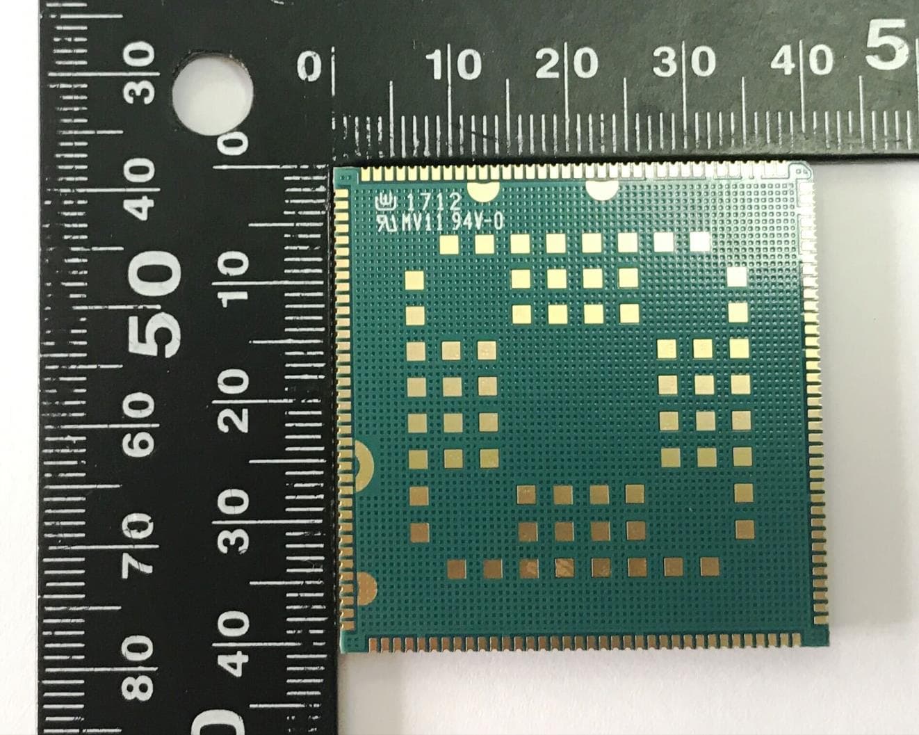
Click to zoom
Application Details
- Equipment Class
- PCB - PCS Licensed Transmitter
- Date of Grant
- May 18, 2023
- Application Purpose
- Original Equipment
- Date of Application
- May 18, 2023
- Equipment Note
- GPS Tracking/ Entertainment Tablet Device
- Frequency Range
- 815.50000000 - 822.50000000
- Company
- Syncwise LLC
- Country
- United States
Documents & Files
Document Text
Text extracted from the exhibit documents filed with the FCC. Open a document above to read the original.
Users Manual
T10-R – Device Manual WARNING: NEVER HOT PLUG/UNPLUG DEVICE FROM POWER CABLE 1.Set power supply to 18V 2.Power off power supply 3.Connect T10- R device to power supply using 5P connector cable with alligator clips 4.Power on power supply at 18V 5.Device should boot. Check Android status bar (found at top of LCD screen) to confirm device is charging and receiving power. Powering on T10-R Device – Power Supply I. Device Setup Warning: This device complies with part 15 of the FCC Rules. Operation is subject to the following two conditions: (1) This device may not cause harmful interference, and (2) this device must accept any interference received, including interference that may cause undesired operation I. Operating Device 1.When powered on, device will automatically boot and automatically provisions to known networks 2.Device will connect to LTE networks by default, but has 3G fall back in case LTE is not available 3..... . Device Default Settings 1.T1 0-R will boot up when connected to power supply, and can be powered at 12-18V 2.Device can be Powered Off/placed into Shipmode(complete power off) by: -Pressing the center Power button for three seconds > enter Passcode: 102938 > Select Power Off/Shipmode 3.T1 0-R is an Android device, and user can access Android settings menu by: Selecting Settings icon on Android home screen > enter Passcode: 102938 Device Power Modes 1.Power on T10-R device by power supply with 18V and ensure it is fully charged (depending on duration of the test) 2.Power off power supply, and disconnect 5P connector cable to power supply 3.Connect T10-R device 5P cable to the 5P USB adapter cable (pink), and connect to PC Note: Device will not charge when connected to PC Connecting T10-R Device – via USB to PC II. Testing - AT Commands 1.Be sure device is disconnected from power supply 2.Power off and place in ship mode (to power off hold the center button 3 sec > enter passcode 102938 > select shipmode 3.Undo the screws on the back cover of the battery case to remove cover piece. 4.Disconnect the battery cable at the connectors (be very careful and only pull on the connectors to avoid damage to any wires) 5.Loosen the screws on the back housing piece of the device, followed by the front screws 6.Open the device VERY CAREFULLY to avoid any damage to cables/connections 7.Locate the SIM card on the board and replace a)If able to replace without removing any connections, proceed carefully b)If unable to easily replace SIM card, disconnect necessary cable connections –V ERY carefully and record exact point to reconnect 8.Reconnect all cable connections. Assemble housing back together, fasten the back screws. Connect the battery cables, repla ce battery cover, and secure screws. Disassembling Device 1.Power on device and then connect to PC using 5P/USB adapter cable 2.Select the SETTINGS icon on the Android home screen 3.Enter passcode: l1powered 4. Scroll down to About Tablet > tap 12 times to access Developer Options 5.Scroll down to Networking and Enable Debugging, updateUSB Configuration, from Charging to MTP 6.Check PC and device should appear as a recognized device 7.Unzip SC20 zip file 8.Copy file path for ad b_fastbootfolder (e.g.C:\Users\User\Desktop\SC20\adb_fastboot) 9.Open Command Prompt (cmd.exe) on your PC 10. Type cdand paste folder path you previously copied (e.g. cdC:\Users\Pixel\Desktop\SC20\adb_fastboot) 11.Type adbshell and press Enter (if everything successful msm8909_Viper_T10-R:/ # should appear) 12.Typesuand press Enter 13.Typesetproppersist.sys.usb.configdiag,serial_smd,rmnet_qti_bam,adb 14.Reconnect USB (After that device should be recognized asPID 9091 15.Go to Device Manager on your PC 16.Look for Android devices under Other devices section 17.Right click on each one of them and select Update driver 18.Select Browse my computer for drivers and locate rivers which were included in SC20 zip file ( folderQuectel_SC20_signed_usb_driver_10051.7_20180211) 19.Repeat step 17 and 18 for each device which is under Other devices section and marked as Android 20.If everything went successful PID 9091 will appear under Modems section 21.Right click on that Modem to select Properties, where you will be able to check what port, it is connectedt o. 22.Openh yperterminal/teratermand connect to port mentioned in step 21 23.Upon successful result you will be able to enter AT commands. Recognizing Device on PC II. Testing - AT Commands III. RSE Spot Check 1.Be sure device is disconnected from power supply/PC 2.Power off device and place in ship mode (to power off hold the center button 3 sec > enter passcode 102938 > select shipmode 3.Undo the screws on the back cover of the battery case to remove cover piece. 4.Disconnect the battery cable at the connectors (be very careful and only pull on the connectors to avoid damage to any wires) 5.Loosen the screws on the back housing piece of the device, followed by the front screws 6.Open the device VERY CAREFULLY to avoid any damage to cables/connections 7.Locate the thick white LVDS FPC cable (which connects the LCD). This will need to be disconnected from the connector that is found on the front housing piece. PLEASE BE EXTREMELY CAREFUL WHEN DISCONNECTING FPCs for LCD. Disassembling Device Figure 3-7: LVDS FPC III. RSE Spot Check... Continued a)If able to disconnect without removing any cable connections, proceed carefully b)If unable to easily access, disconnect necessary cable connections – VERY carefully and record exact point to reconnect 8.Disconnect LVDS strip, by removing tape that may be placed over the connector (save for re-installation), then flipping up the connector’s tab/clip piece, then pull the FPC out of the connector and let it hang loose in the housing. 9.Also disconnect the skinny white FPC (for the cap touch) that is connected onto the PCB. Disconnect carefully following the same in s t ru c t io n s lis t e d in s t e p # 8 . 10.Keep test SIM card installed in device. 11.Reconnect all cable connect…
Text truncated - open the document above for the full version.
Users Manual
T10-R – Device Manual WARNING: NEVER HOT PLUG/UNPLUG DEVICE FROM POWER CABLE 1.Set power supply to 18V 2.Power off power supply 3.Connect T10-R device to power supply using 5P connector cable with alligator clips 4.Power on power supply at 18V 5.Device should boot. Check Android status bar (found at top of LCD screen) to confirm device is charging and receiving power. Powering on T10-R Device – Power Supply I. Device Setup 1.Power on T10-R device by power supply with 18V and ensure it is fully charged (depending on duration of the test) 2.Power off power supply, and disconnect 5P connector cable to power supply 3.Connect T10-R device 5P cable to the 5P USB adapter cable (pink), and connect to PC Note: Device will not charge when connected to PC Connecting T10-R Device – via USB to PC I. Operating Device 1.When powered on, device will automatically boot and automatically provisions to known networks 2.Device will connect to LTE networks by default, but has 3G fall back in case LTE is not available 3..... . Device Default Settings 1.T1 0-R will boot up when connected to power supply, and can be powered at 12-18V 2.Device can be Powered Off/placed into Shipmode(complete power off) by: -Pressing the center Power button for three seconds > enter Passcode: 102938 > Select Power Off/Shipmode 3.T1 0-R is an Android device, and user can access Android settings menu by: Selecting Settings icon on Android home screen > enter Passcode: 102938 Device Power Modes II. Testing - AT Commands 1.Be sure device is disconnected from power supply 2.Power off and place in ship mode (to power off hold the center button 3 sec > enter passcode 102938 > select shipmode 3.Undo the screws on the back cover of the battery case to remove cover piece. 4.Disconnect the battery cable at the connectors (be very careful and only pull on the connectors to avoid damage to any wires) 5.Loosen the screws on the back housing piece of the device, followed by the front screws 6.Open the device VERY CAREFULLY to avoid any damage to cables/connections 7.Locate the SIM card on the board and replace a)If able to replace without removing any connections, proceed carefully b)If unable to easily replace SIM card, disconnect necessary cable connections –VERY carefully and record exact point to reconnect 8. Reconnect all cable connections. Assemble housing back together, fasten the back screws. Connect the battery cables, repla ce battery cover, and secure screws. Disassembling Device 1.Power on device and then connect to PC using 5P/USB adapter cable 2.Select the SETTINGS icon on the Android home screen 3.Enter passcode: l1powered 4.Scroll down to About Tablet > tap 12 times to access Developer Options 5.Scroll down to Networking and Enable Debugging, updateUSB Configuration, from Charging to MTP 6.Check PC and device should appear as a recognized device 7.Unzip SC20 zip file 8.Copy file path for adb_fastbootfolder (e.g.C:\Users\User\Desktop\SC20\adb_fastboot) 9.Open Command Prompt (cmd.exe) on your PC 10.Type cdand paste folder path you previously copied (e.g. cdC:\Users\Pixel\Desktop\SC20\adb_fastboot) 11.Type adbshell and press Enter(if everything successful msm8909_Viper_T10-R:/ # should appear) 12.Typesuand press Enter 13.Typesetproppersist.sys.usb.configdiag,serial_smd,rmnet_qti_bam,adb 14.Reconnect USB (After that device should be recognized asPID 9091 15.Go to Device Manager on your PC 16.Look for Android devices under Other devices section 17.Right click on each one of them and select Update driver 18.Select Browse my computer for drivers and locate rivers which were included in SC20 zip file (folderQuectel_SC20_signed_usb_driver_10051.7_20180211) 19.Repeat step 17 and 18 for each device which is under Other devices section and marked as Android 20.If everything went successful PID 9091 will appear under Modems section 21.Right click on that Modem to select Properties, where you will be able to check what port, it is connectedto. 22.Openhyperterminal/teratermand connect to port mentioned in step 21 23.Upon successful result you will be able to enter AT commands. Recognizing Device on PC II. Testing - AT Commands III. RSE Spot Check 1.Be sure device is disconnected from power supply/PC 2.Power off device and place in ship mode (to power off hold the center button 3 sec > enter passcode 102938 > select shipmode 3.Undo the screws on the back cover of the battery case to remove cover piece. 4.Disconnect the battery cable at the connectors (be very careful and only pull on the connectors to avoid damage to any wires) 5.Loosen the screws on the back housing piece of the device, followed by the front screws 6.Open the device VERY CAREFULLY to avoid any damage to cables/connections 7.Locate the thick white LVDS FPC cable (which connects the LCD). This will need to be disconnected from the connector that is found on the front housing piece. PLEASE BE EXTREMELY CAREFUL WHEN DISCONNECTING FPCs for LCD. Disassembling Device Figure 3-7: LVDS FPC III. RSE Spot Check... Continued a)If able to disconnect without removing any cable connections, proceed carefully b)If unable to easily access, disconnect necessary cable connections – VERY carefully and record exact point to reconnect 8.Disconnect LVDS strip, by removing tape that may be placed over the connector (save for re-installation), then flipping up the connector’s tab/clip piece, then pull the FPC out of the connector and let it hang loose in the housing. 9.Also disconnect the skinny white FPC (for the cap touch) that is connected onto the PCB. Disconnect carefully following the same in s t ru c t io n s lis t e d in s t e p # 8 . 10.Keep test SIM card installed in device. 11.Reconnect all cable connections. Assemble housing back together, fasten the back screws into the housing. Connect the batterycab le s , replace battery cover, and secure screws. Disassembling Device Figure 3-8: LVDS to LCD Figure 3-9: Touch cap FPC to PCB
External Photos
Photographs of EUT Report No.: EP741007 Brand Name: Quectel / Model Name: SC20-A Sporton International (KunShan) INC. Page Number : 1 of 8 TEL : 86-0512-5790-0158 Report Issued Date : Aug. 11, 2017 FAX : 86-0512-5790-0958 Report Version : Rev. 01 FCC ID : XMR201706SC20A 720510 1. External Photograph of EUT Photographs of EUT Report No.: EP741007 Brand Name: Quectel / Model Name: SC20-A Sporton International (KunShan) INC. Page Number : 2 of 8 TEL : 86-0512-5790-0158 Report Issued Date : Aug. 11, 2017 FAX : 86-0512-5790-0958 Report Version : Rev. 01 FCC ID : XMR201706SC20A Photographs of EUT Report No.: EP741007 Brand Name: Quectel / Model Name: SC20-A Sporton International (KunShan) INC. Page Number : 3 of 8 TEL : 86-0512-5790-0158 Report Issued Date : Aug. 11, 2017 FAX : 86-0512-5790-0958 Report Version : Rev. 01 FCC ID : XMR201706SC20A 2. Photograph of Accessory Bluetooth & WLAN Antenna port WWAN Main Antenna port WWAN Diversity Antenna port GNSS Antenna port Photographs of EUT Report No.: EP741007 Brand Name: Quectel / Model Name: SC20-A Sporton International (KunShan) INC. Page Number : 4 of 8 TEL : 86-0512-5790-0158 Report Issued Date : Aug. 11, 2017 FAX : 86-0512-5790-0958 Report Version : Rev. 01 FCC ID : XMR201706SC20A Photographs of EUT Report No.: EP741007 Brand Name: Quectel / Model Name: SC20-A Sporton International (KunShan) INC. Page Number : 5 of 8 TEL : 86-0512-5790-0158 Report Issued Date : Aug. 11, 2017 FAX : 86-0512-5790-0958 Report Version : Rev. 01 FCC ID : XMR201706SC20A Photographs of EUT Report No.: EP741007 Brand Name: Quectel / Model Name: SC20-A Sporton International (KunShan) INC. Page Number : 6 of 8 TEL : 86-0512-5790-0158 Report Issued Date : Aug. 11, 2017 FAX : 86-0512-5790-0958 Report Version : Rev. 01 FCC ID : XMR201706SC20A Photographs of EUT Report No.: EP741007 Brand Name: Quectel / Model Name: SC20-A Sporton International (KunShan) INC. Page Number : 7 of 8 TEL : 86-0512-5790-0158 Report Issued Date : Aug. 11, 2017 FAX : 86-0512-5790-0958 Report Version : Rev. 01 FCC ID : XMR201706SC20A
Internal Photos
image of the bottom of the module Below is an image of the inside of the SC20-A module.
Internal Photos
Photographs of EUT Report No.: EP741007 Brand Name: Quectel / Model Name: SC20-A Sporton International (KunShan) INC. Page Number : 8 of 8 TEL : 86-0512-5790-0158 Report Issued Date : Aug. 11, 2017 FAX : 86-0512-5790-0958 Report Version : Rev. 01 FCC ID : XMR201706SC20A 3. Internal Photograph of EUT
Test Report
2JF0424P Product Datasheet Key Features CELLULAR / LTE - 698-960 MHz - 1710-2170 MHz - 2500-2700 MHz Embedded Antenna Self-Adhesive High Performance Ground Plane Independent Dimensions 136.8 x 32.6 x 0.2 mm Customizable Cable and Connector www.2j-antennae.comwww.2j-antennasusa.com Page: 1/9 CELLULAR / LTE Flexible Polymer www.2j-antennae.comwww.2j-antennasusa.com Page: 2/9 1. Antenna and electrical specifications Parameters Standards Band (MHz) Frequency (MHz) Return Loss (dB) VSWR Efficiency (%) Peak Gain (dBi) Average Gain (dB) Impendance (Ohm) Polarisation Radiation Pattern Max. Input Power (W) Connector Type Cable Length Cable Type 700/850/900 698-960 ~-13.6 ~1.7:1 ~58 ~1.5 ~-2.4 CELLULAR / LTE Antenna 2G,3G and 4G 1700/1800/1900/2100 1710-2170 ~-23.5 ~1.1:1 ~74 ~3.1 ~-1.3 50 Linear Omni-Directional 25 Most RF Connectors (U.FL Standard) Any Cable Length (150mm Standard) Other Cables Available (1.37mm Standard) 2600 2500-2700 ~-11.8 ~1.7:1 ~61 ~3.5 ~-2.0 Antenna Measurement Conditions: Mounted on 30 x 30 cm ABS Plate with 2.5 mm Thickness 150 mm 1.37 mm Mini-Coax Cable Measured in Certified CTIA 3D Anechoic Chamber 2. Mechanical and environmental specifications Specifications Mounting Type Dimensions (mm) Adhesive Type Material Operating Temperature (C) Storage Temperature (C) Substance Compliance 2JF0424P Adhesive Mount 136.8 x 32.6 x 0.2 3M 467 Flexible Polymer -40 to +85 -40 to +85 RoHS -25 -20 -15 -10 -5 0 6007008009001000110012001300140015001600170018001900200021002200230024002500260027002800 Re tur n L os s (dB) Frequency (MHz) 0 1 2 3 4 5 6 7 6007008009001000110012001300140015001600170018001900200021002200230024002500260027002800 VS W R Frequency (MHz) www.2j-antennae.comwww.2j-antennasusa.com Page: 3/9 3. Antenna parameters www.2j-antennae.comwww.2j-antennasusa.com Page: 4/9 0 20 40 60 80 100 6007008009001000110012001300140015001600170018001900200021002200230024002500260027002800 E f fi ci ency ( %) Frequency (MHz) -1 0 1 2 3 4 5 6007008009001000110012001300140015001600170018001900200021002200230024002500260027002800 P eak G ai n (dBi ) Frequency (MHz) -4 -3 -2 -1 0 1 6007008009001000110012001300140015001600170018001900200021002200230024002500260027002800 A v er ag e G ain (dB) Frequency (MHz) www.2j-antennae.comwww.2j-antennasusa.com Page: 5/9 Radiation pattern reference www.2j-antennae.comwww.2j-antennasusa.com Page: 6/9 750 and 850 MHz Radiation pattern 940 and 1750 MHz Radiation pattern www.2j-antennae.comwww.2j-antennasusa.com Page: 7/9 1850 and 1950 MHz Radiation pattern 2100 and 2600 MHz Radiation pattern www.2j-antennae.comwww.2j-antennasusa.com Page: 8/9 4. Antenna drawings 32,6 136,8 100 ±2 60 1,7 mm www.2j-antennae.comwww.2j-antennasusa.com Page: 9/9 5. Antenna Images
Test Report
2JF0202P Product Datasheet Key Features 2.4/5.0/6.0 GHz ISM - 2410-2490 MHz - 4920-7125 MHz Embedded Antenna Wifi 6E Antenna High Performance Ground Plane Independent Self-Adhesive Dimensions 30 × 30 × 0.2 mm Customizable Cable and Connector www.2j-antennae.comwww.2j-antennasusa.com Page: 1/8 2.4/5.0/6.0 GHz ISM Flexible Polymer www.2j-antennae.comwww.2j-antennasusa.com Page: 2/8 1. Antenna and electrical specifications Parameters Standards Band (MHz) Frequency (MHz) Return Loss (dB) VSWR Efficiency (%) Peak Gain (dBi) Average Gain (dB) Impendance (Ohm) Polarisation Radiation Pattern Max. Input Power (W) Connector Type Cable Length Cable Type 2.4 GHz 2410-2490 ~-20.2 ~1.2:1 ~76.3 ~4.4 ~-1.2 2.4/5.0/6.0 GHz ISM Antenna WiFi 6E, BT, ZigBee, ISM, SigFox, LoRa 50 Linear Omni-Directional 25 Most RF Connectors (U.FL Standard) Any Cable Length (100mm Standard) Other Cables Available (1.37mm Standard) 5.0 GHz 4920-5925 ~-14.8 ~1.5:1 ~74.7 ~6.7 ~-1.3 6.0 GHz 5925-7125 ~-15.2 ~1.8:1 ~61.0 ~5.0 ~-1.4 Antenna Measurement Conditions: Mounted 30x30x0.25 cm ABS Plate 100 mm of 1.37 mm Cable Measured in Certified CTIA 3D Anechoic Chamber 2. Mechanical and environmental specifications Specifications Mounting Type Dimensions (mm) Adhesive Type Material Operating Temperature (C) Storage Temperature (C) Substance Compliance 2JF0202P Self-Adhesive 30 × 30 × 0.2 3M 467 Flexible Polymer -40 to +85 -40 to +85 RoHS www.2j-antennae.comwww.2j-antennasusa.com Page: 3/8 3. Antenna parameters -20 -15 -10 -5 0 230025502800305033003550380040504300455048005050530055505800605063006550680070507300 R e tu rn L os s (dB) Frequency (MHz) 0 1 2 3 4 5 6 7 8 9 230025502800305033003550380040504300455048005050530055505800605063006550680070507300 V S WR Frequency (MHz) www.2j-antennae.comwww.2j-antennasusa.com Page: 4/8 0 10 20 30 40 50 60 70 80 90 230025502800305033003550380040504300455048005050530055505800605063006550680070507300 E f ficie n cy (%) Frequency (MHz) 0 1 2 3 4 5 6 7 230025502800305033003550380040504300455048005050530055505800605063006550680070507300 P eak G ain (dBi) Frequency (MHz) www.2j-antennae.comwww.2j-antennasusa.com Page: 5/8 Radiation pattern reference -5 -4 -3 -2 -1 0 230025502800305033003550380040504300455048005050530055505800605063006550680070507300 A v er ag e Gain (d B) Frequency (MHz) www.2j-antennae.comwww.2j-antennasusa.com Page: 6/8 2450 and 5500 MHz Radiation pattern 6500 MHz Radiation pattern www.2j-antennae.comwww.2j-antennasusa.com Page: 7/8 4. Antenna drawings 100 ±2 30 30 3 6,9 max.1,47 5,5 2 117,5 Adhesive tape UFL www.2j-antennae.comwww.2j-antennasusa.com Page: 8/8 5. Antenna Images
Test Setup Photos
Product Front View: Product Back View: Left Side View: Right Side View: Internal View Front Housing: Back View PCB: Internal View Back Housing:
Contact Information
Applicant
Todd Nowak(Account and Product Manager)
Technical Contact
Syncwise LLCTodd Nowak
[email protected]16195189111
2308 Kettner Blvd Suite B · San Diego, California · United States
Test Firm
EUROFINS ELECTRICAL AND ELECTRONIC TESTING NA, INCGreg Kovolenko
Technical Specifications
| # | Rule Parts | Frequency Range | Power Output | Emission | Tolerance |
|---|---|---|---|---|---|
| 36 | 22H,9 | 815.5 MHz - 822.5 MHz | 219.80 mW | 2M73G7D | 0.0045 ppm |