2A3ICDT-128Digital meat thermometer
Shenzhen Goldgood Instrument Limited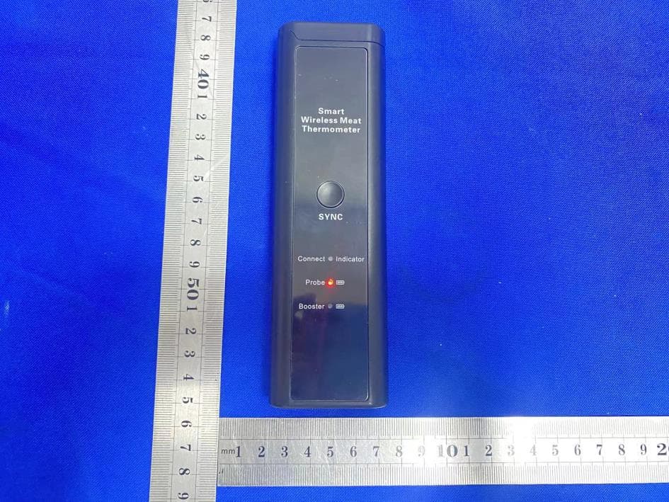
Click to zoom
Application Details
- Equipment Class
- DTS - Digital Transmission System
- Date of Grant
- Sep 26, 2023
- Application Purpose
- Original Equipment
- Date of Application
- Sep 26, 2023
- Equipment Note
- Digital meat thermometer
- Frequency Range
- 2402.00000000 - 2480.00000000
- Country
- China
Documents & Files
Document Text
Text extracted from the exhibit documents filed with the FCC. Open a document above to read the original.
Users Manual
Wilress Smart Meat Thermometer User Manual Thank you for choosing our Wireless Smart Meat Thermometer. This user manual will guide you through the setup process, explain the features and functions, and provide tips for optimal use. Please read this manual carefully before using the device. To access the full range of features and functionalities, we recommend scanning the QR code provided below to download and install the companion mobile app for your smart meat thermometer. - Meat Thermometer Probe - Booster - USB Charging Cable - User Manual Package Contents: Introduction Congratulations on your new Smart Cooking Thermometer! This wireless device is packed with features that allow you to monitor your food's internal temperature, check the ambient temperature, and even keep track of the elapsed time of cooking. You can do it all remotely from your smart device. Enjoy the convenience and precision of this advanced cooking thermometer! Features 2 1 9 8 7 6 3 4 5 15 14 13 11 12 10 1.Booster Cover 2. SNYC Button 3. Weep Hole 4. USB Charging Port 5. Speaker 6. Booster Battery Power Indicator 7. Probe Battery Power Indicator 8. Bluetooth Connection Indicator 9. Rear Magnets 10. Ambient Temperature Sensor 11. Ceramic Handle 12. Notch 13. Stainless Steel Probe 14. Internal Temperature Sensor 15. Charging Cable 1. Booster Cover: open or close the cover to take the probe in or out. It also serves as a power source to charge the probe. 2. SNYC Button: serves 2 functions: ·Press and hold for 3 seconds to pair the booster and the probe; ·Press once to silence the booster’s alarm when the meat temperature reaches the target temperature. 3. Weep Hole: prevent residual liquids entering to booster to affect usage. 4. USB Charging Port. 5. Beeper: when the internal temperature reaches the target level or the ambient temperature exceed its preset range, a sound will be emitted from here. Additionally, if the internal temperature exceeds max 100°C/212 ̊F or the ambient temperature exceeds its max 300°C/572 ̊F, an over- temperature warning sound will be activated. 6. Booster Battery Power Indicator: when it flashes red, this indicates the booster battery power is low and needs to be recharged. When the booster is being charged, the red light will always be on. Once the booster is fully charged, the light will be off. 7. Probe Charging Indicator: when it flashes red, it indicates the probe battery power is low and needs to be recharged. When the probe is being charged, the red light will always be on. After the probe is fully charged, the light will be off. 8. Bluetooth Connection Indicator: if the probe and the booster are connected, the indicator will be blue constantly . If the probe losses connection with the booster, it will flash red. When the probe is placed in the booster for charging and storage, the light will be off. 9. Rear Magnets: 2 big magnets back side where able to stick on any steel surface. 10. Ambient Temperature Sensor: the ambient temperature sensor is housed toward the ceramic end and has a range of 14 ̊F to 572 ̊F/-10°C to 300°C. 11. Ceramic Handle. 12. Notch: when the probe is inserted into meat for measuring the meat's internal temperature, the probe must be inserted deep enough so that the meat will cover this notch. 13. Stainless Steel Probe. 14. Internal Temperature Sensor: the internal temperature sensor is positioned at the tip and has a range of 14 ̊F to 212 ̊F/-10°C to100°C. 15. Charging Cable. Before First Use Follow these steps below to set up your “Temprobe” and master the art of cooking like a professional! Step 1: Begin by downloading and installing the "Temprobe" App. You can do this by either scanning the QR code provided above or by searching for "Temprobe" on the Apple Store (for iOS devices) or the Google Play Store (for Android devices). Download the App and complete the installation process on your smart device. *For iPhone and iPad users, ensure that your device is running iOS 9.0 or above. *Android users should have devices with Android version 4.4 or above. Android users may need to grant necessary permissions to the App as requested by the Android system. Step 2: Enable Bluetooth and Location on your smart device under the Settings section. Step 3: It is important to fully charge both the booster and the probe. Connect the provided USB charging cable to any USB charger and charge the booster. Once the booster is fully charged, the battery indicator light will turn off. Place the probe in the booster to charge it as well. The probe's battery indicator light will also turn off when it is fully charged. Step 4: If you ever need to re-pair the devices or if you have a new probe or booster to be paired, please follow the instructions below: 1. Take out the probe from the booster. 2. Press and hold the SYNC button until you observe the Connection Indicator flashing blue rapidly. 3. Allow a few seconds for the Connection Indicator to keep blue constantly. This signifies that the probe and the booster have been successfully paired. Once paired, there is no need to repeat the pairing process for future use. Step 5: Connect the booster to your smart device 1. Remove the probe from the booster. 2. Launch the "Temprobe" App and it will scan the booster nearby automatically. After a few Cleaning and Maintenance 1. Thoroughly clean and dry the probe before placing it in the charging nest of the booster. It is important to maintain a clean probe for proper charging. Hand wash the probe using mild soapy water, avoiding the use of overly abrasive sponges or cleaners to prevent scratching. 2. To clean the booster, simply wipe it down with a damp cloth. The booster is not dishwasher-safe and is not waterproof, so avoid immersing it in water. Caution 1.Always insert the probe beyond the designated safety notch to avoid product damage and personal injury. 2.DO NOT use the probe in microwaves ovens. 3.Do NOT place the booster directly on the grill cover or in close proximity to any…
Text truncated - open the document above for the full version.
Attestation Statements
(Shenzhen Goldgood Instrument Limited) (September 21, 2023) Eurofins Electrical and Electronic Testing NA, Inc. 914 West Patapsco Avenue Baltimore, MD 21230 RE: Attestation Statements Part 2.911(d)(5)(i) request for (FCC ID: 2A3ICDT-128) [Shenzhen Goldgood Instrument Limited] (“the applicant”) certifies that the equipment for which authorization is sought is not “covered” equipment prohibited from receiving an equipment authorization pursuant to section 2.903 of the FCC rules. Sincerely, (Applicant signature) (Applicant printed name) Kui Zou (Shenzhen Goldgood Instrument Limited) (September 21, 2023) Eurofins Electrical and Electronic Testing NA, Inc. 914 West Patapsco Avenue Baltimore, MD 21230 RE: Attestation Statements Part 2.911(d)(5)(ii) request for (FCC ID: 2A3ICDT-128) [Shenzhen Goldgood Instrument Limited] (“the applicant”) certifies that, as of the date of the filing of the application, the applicant is not identified on the Covered List as an entity producing “covered” equipment. Sincerely, (Applicant signature) (Applicant printed name) Kui Zou
Attestation Statements
Attestation Statements (September 21, 2023) TO: Federal Communications Commission Authorization and Evaluation Division 7435 Oakland Mills Road Columbia, MD 21046, USA RE: Attestation Statements Part 2.911(d)(7) request for (FCC ID: 2A3ICDT-128) (Shenzhen Goldgood Instrument Limited), the undersigned, hereby authorize (GOJA LLC) to act as our designated U.S. agent for service of process, (Shenzhen Goldgood Instrument Limited) accepts to maintain an agent for no less than one year after the grantee has terminated all marketing and importation or the conclusion of any Commission-related proceeding involving the equipment. (GOJA LLC) accepts the responsibility to act as designated U.S. agent for service of process, provides an agent for no less than one year after the grantee has terminated all marketing and importation or the conclusion of any Commission-related proceeding involving the equipment. Applicant Information: Company name: Shenzhen Goldgood Instrument Limited Contact Name: Kui Zou Address: Huafeng High-tech Industrial Park Nanhuan Road, Bao'an District Shenzhen, Guangdong, China Telephone No: 13538214502 Email: [email protected] U.S. Agent Information: Company Name: GOJA LLC Address: 8400 N.W. 36th street Suite 500 Doral, FL 33166, USA Contact Name: Casandra Poppe Telephone No: +1-786-534-6112 Email: [email protected] FRN: 0034267005 Applicant Signature: Agent Signature: Applicant printed name: Kui Zou Agent printed name: Casandra Poppe
Cover Letter(s)
Shenzhen Goldgood Instrument Limited Model Difference Data:September 21, 2023 Product description: Digital meat thermometer Model name: DT-128, DT-129, DT-130, DT-131, DT-132, DT-133 Trade Name: N/A FCC ID: 2A3ICDT-128 All the model are the same circuit and RF module, except model names . Regards Sincerely Client’s signature : Client’s name / title : Kui Zou(General Manager) Contact information / address:Huafeng High-tech Industrial Park Nanhuan Road, Bao'an District Shenzhen, Guangdong, China
Cover Letter(s)
Shenzhen Goldgood Instrument Limited (September 21, 2023) Eurofins Electrical and Electronic Testing NA, Inc. 914 West Patapsco Avenue Baltimore, MD 21230 RE: CONFIDENTIALITY REQUEST FOR (Digital meat thermometer / DT-128, DT- 129, DT-130, DT-131, DT-132, DT-133 / FCC ID: 2A3ICDT-128 ) To Whom It May Concern: This letter serves as an official request for confidentiality under sections 0.457 and 0.459 of CFR 47. We have requested that the Exhibits Long-Term Confidentiality Short-Term Confidentiality NOTE 2 ID Label/Location No No Attestation Statement No No External Photos No ☐ Block Diagram ☒ ☐ Schematics ☒ ☐ Test Report No No Test Setup Photos No ☐ User’s Manual ☐ NOTE 1 ☒ Internal Photos ☐ NOTE 1 ☒ Parts List / Tune Up ☐ ☐ RF Exposure Info No No Operational Description ☒ ☐ Cover Letter(s) No No SDR Software / Security Info ☐ No required to be submitted with this application be permanently withheld from public review. Above mentioned document contains detailed system and equipment description are considered as proprietary information in operation of the equipment. The public disclosure of above documents might be harmful to our company and would give competitor an unfair advantage in the market. Please contact me if there is any information you may need. Sincerely, Signature: Name: Kui Zou Title: General Manager
Cover Letter(s)
Shenzhen Goldgood Instrument Limited (September 21, 2023) Eurofins Electrical and Electronic Testing NA, Inc. 914 West Patapsco Avenue Baltimore, MD 21230 RE: LETTER OF AGENT AUTHORIZATION To Whom It May Concern: We, the undersigned, hereby authorize (Shenzhen CTB Testing Technology Co., Ltd.) to act on our behalf in all matters relating to application for equipment authorization, including the signing of all documents relating to these matters. We also hereby certify that no party to the application authorized hereunder is subject to the denial of benefits, including FCC benefits, pursuant to Section 5301 of the Anti-Drug Abuse Act of 1988, 21 U.S.C.853(a). This agreement expires one year from the current date. Sincerely, Signature: Name: Kui Zou Title: General Manager
External Photos
External Photos
ID Label/Location Info
FCC ID LABEL: Label Location: FCC ID: 2A3ICDT-128 Model No.: DT-128
Internal Photos
Internal Photos ANT
RF Exposure Info
Shenzhen CTB Testing Co., Ltd. FCC ID: 2A3ICDT-128 Portable device According to §15.247(e)(i) and §1.1307(b)(1), systems operating under the provisions of this section shall be operated in a manner that ensures that the public is not exposed to radio frequency energy level in excess of the Commission’s guidelines. According to KDB447498 D01 General RF Exposure Guidance V06 The 1-g SAR and 10-g SAR test exclusion thresholds for 100 MHz to 6 GHz at test separation distances ≤ 50 mm are determined by: [(max. power of channel, including tune-up tolerance, mW)/(min. test separation distance, mm)]·[√f(GHZ)] ≤ 3.0 for 1-g SAR and ≤ 7.5 for 10-g extremity SAR, where: • f(GHZ) is the RF channel transmit frequency in GHz • Power and distance are rounded to the nearest mW and mm before calculation • The result is rounded to one decimal place for comparison When the minimum test separation distance is < 5 mm, a distance of 5 mm is applied to determine SAR test exclusion. BLE: Modulation Channel Freq. (GHz) Conduct ed power (dBm) Conducte d power (mW) Tune-up power (dBm) Max tune-up power (dBm) Max tune-up power (mW) Distance (mm) Result calculatio n SAR Exclusion threshold SAR test exclusion 2.402 -0.841 0.82 0±1 1.00 1.26 <5 0.39023 3.00 YES 2.44 -1.407 0.72 -1±1 0.00 1.00 <5 0.31241 3.00 YES 2.480 -1.398 0.72 -1±1 0.00 1.00 <5 0.31496 3.00 YES GFSK Conclusion: For the max result : 0.39023≤ FCC Limit 3.0 for 1g SAR.
Test Report
Product Number: AN2400-150MHFIPEX Product Name:2 .4GHz Index: 1. Specification 2. Characteristics and Reliability Test 3. Antenna - S Parameter Test Data 2023.9.5 Manufacturer: Shenzhen Goldgood Instrument Limited 5th Floor, Elevator 10, Block B, Huafeng High-tech Industrial Park, Nanhuan Road, Shajing Town, Bao'an District, Shenzhen City, Guangdong Province, China. Product Number: AN2400-150MHFIPEX Product Name:2 .4GHz A.ElectricalCharacteristics Frequency 2400~2500MHz S.W.R. <=2.0 AntennaGain1.5dBi0.7 Polarization Linear Impedance 50Ohm 2.CharacteristicsandReliabilityTest 1. Specification 2023.9.5 2023.9.5 3.Antenna-SParameterTestDat Product Number: AN2400-150MHFIPEX Product Name:2 .4GHz a 2023.9.5 Product Number: AN2400-150MHFIPEX Product Name:2 .4GHz 2023.9.5
Test Report
Shenzhen CTB Testing Technology Co., Ltd. Report No.: CTB230908025RFX Report Tel: 4008-707-283 Web: http://www.ctb-lab.net Page 1 of 35 TEST REPORT Compiled by: Reviewed by: Approved by: Zhou Kui Arron Liu Bin Mei / Director Note: If there is any objection to the inspection results in this report, please submit a written report to the company within 15 days from the date of receiving the report. The test report is effective only with both signature and specialized stamp. This result(s) shown in this report refer only to the sample(s) tested. Without written approval of Shenzhen CTB Testing Technology Co., Ltd. this report can’t be reproduced except in full. The tested sample(s) and the sample information are provided by the client. “*” indicates the testing items were fulfilled by subcontracted lab. “#” indicates the items are not in CNAS accreditation scope. Product Name: Digital meat thermometer FCC ID: 2A3ICDT-128 Trademark: N/A Model Number: DT-128, DT-129, DT-130, DT-131, DT-132, DT-133 Prepared For: Shenzhen Goldgood Instrument Limited Address: Huafeng High-tech Industrial Park Nanhuan Road, Bao'an District Shenzhen, Guangdong, China Manufacturer: Shenzhen Goldgood Instrument Limited Address: 5th Floor, Elevator 10, Block B, Huafeng High-tech Industrial Park, Nanhuan Road, Shajing Town, Bao'an District, Shenzhen City, Guangdong Province, China. Prepared By: Shenzhen CTB Testing Technology Co., Ltd. Address: 1&2/F., Building A, No.26, Xinhe Road, Xinqiao, Xinqiao Street, Bao'an District, Shenzhen, Guangdong, China Sample Received Date: Aug. 31, 2023 Sample tested Date: Aug. 31, 2023 to Sep. 13, 2023 Issue Date: Sep. 13, 2023 Report No.: CTB230908025RFX Test Standards FCC Part15.247 ANSI C63.10:2013 Test Results PASS Remark: This is Bluetooth radio test report. Shenzhen CTB Testing Technology Co., Ltd. Report No.: CTB230908025RFX Report Tel: 4008-707-283 Web: http://www.ctb-lab.net Page 2 of 35 TABLE OF CONTENT Test Report Declaration Page 1. VERSION ........................................................................................................................................ 3 2. TEST SUMMARY ........................................................................................................................... 4 3. MEASUREMENT UNCERTAINTY ................................................................................................. 5 4. PRODUCT INFORMATION AND TEST SETUP ............................................................................ 6 4.1 Product Information .......................................................................................................................... 6 4.2 Test Setup Configuration .................................................................................................................. 6 4.3 Support Equipment........................................................................................................................... 6 4.4 Channel List ..................................................................................................................................... 7 4.5 Test Mode ........................................................................................................................................ 7 4.6 Test Environment ............................................................................................................................. 7 5. TEST FACILITY AND TEST INSTRUMENT USED ....................................................................... 8 5.1 Test Facility ...................................................................................................................................... 8 5.2 Test Instrument Used ....................................................................................................................... 8 6. AC POWER LINE CONDUCTED EMISSION ................................................................................ 10 6.1 Block Diagram Of Test Setup ......................................................................................................... 10 6.2 Limit ................................................................................................................................................ 10 6.3 Test procedure ............................................................................................................................... 10 6.4 Test Result ..................................................................................................................................... 12 7. RADIATED SPURIOUS EMISSION ............................................................................................. 14 7.1 Block Diagram Of Test Setup ......................................................................................................... 14 7.2 Limit ................................................................................................................................................ 14 7.3 Test procedure ............................................................................................................................... 15 7.4 Test Result ..................................................................................................................................... 16 8. BAND EDGE AND RF COUNDUCTED SPURIOUS EMISSIONS ............................................... 23 8.1 Block Diagram Of Test Setup ......................................................................................................... 23 8.2 Limit ................................................................................................................................................ 23 8.3 Test procedure ............................................................................................................................... 23 8.4 Test Result ..................................................................................................................................... 24 9. COUDUCTED OUTP…
Text truncated - open the document above for the full version.
Test Setup Photos
Radiated Emission Below 1G Above 1G Conducted emissions
Contact Information
Applicant
Zou Kui(General Manager)
Technical Contact
Shenzhen Goldgood Instrument LimitedKui Zou
[email protected]13538214502
Huafeng High-tech Industrial Park · Shenzhen, Guangdong, · China
Test Firm
Shenzhen CTB Testing Technology Co., Ltd.Rita Xiao
[email protected]86-13538218145
Technical Specifications
| # | Rule Parts | Frequency Range | Power Output |
|---|---|---|---|
| 1 | 15C | 2.40 GHz - 2.48 GHz | 820.00 µW |