2A3MU-F8Geodetic GNSS Receiver
Shanghai EFIX Geomatics Co., Ltd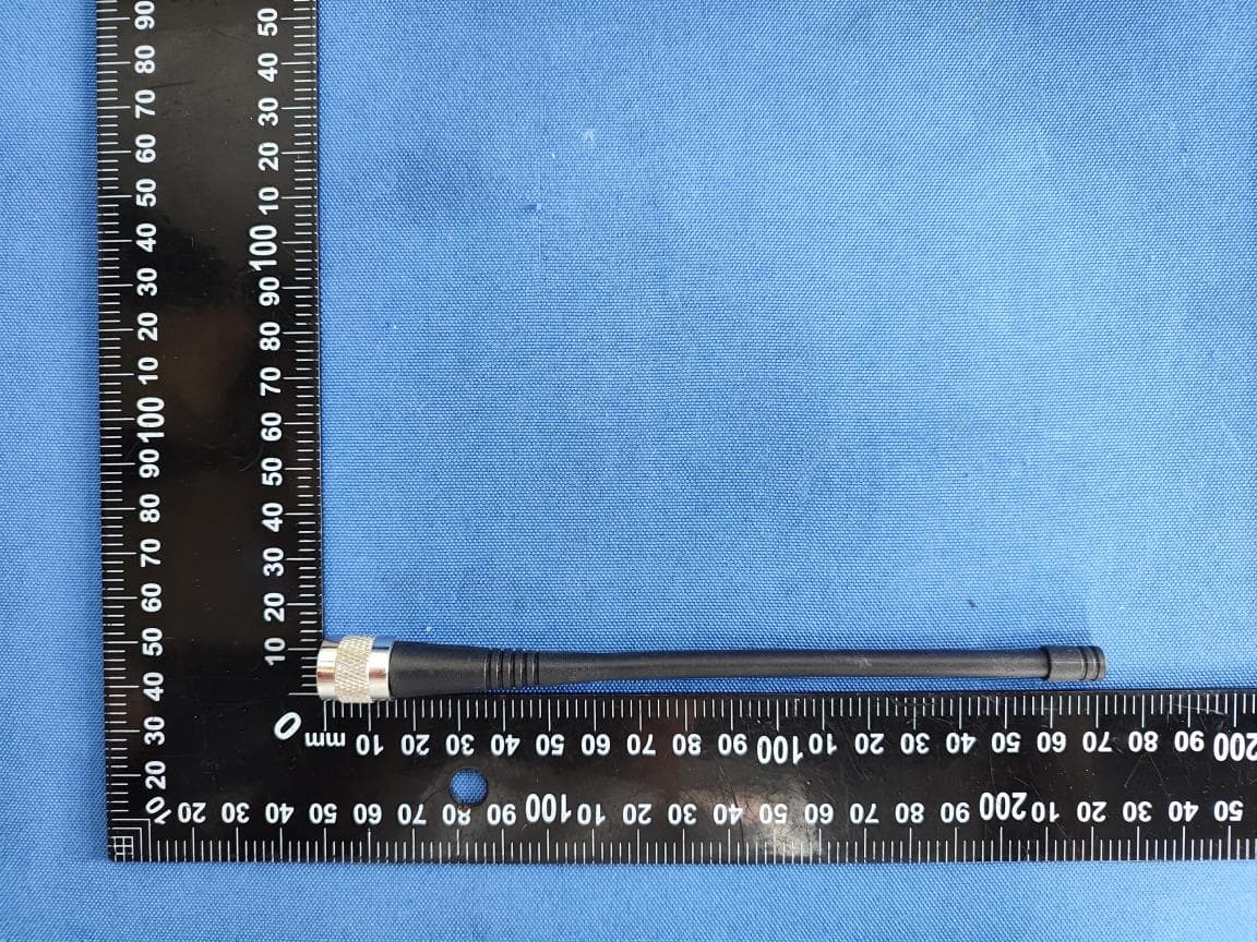
Click to zoom
Application Details
- Equipment Class
- DSS - Part 15 Spread Spectrum Transmitter
- Date of Grant
- Sep 29, 2025
- Application Purpose
- Original Equipment
- Equipment Note
- Geodetic GNSS Receiver
- Frequency Range
- 2402.00000000 - 2480.00000000
- Country
- China
Documents & Files
Document Text
Text extracted from the exhibit documents filed with the FCC. Open a document above to read the original.
Users Manual
Strongersignal,easytofix EFIXF8GNSS USERGUIDE Survey&Engineering|June2023 TableofContent EFIXF8GNSSUSERGUIDE|2023-6Page| 2 TableofContent TableofContent..............................................................................................................2 Preface............................................................................................................................5 Copyright............................................................................................................................5 SafetyWarnings..................................................................................................................5 1Introduction..............................................................................................................6 1.1SafetyInformation........................................................................................................6 1.1.1WarningsandCautions......................................................................................6 1.2RegulationsandSafety.................................................................................................6 1.2.1UseandCare......................................................................................................7 1.3TechnicalSupport.........................................................................................................7 1.4Disclaimer.....................................................................................................................7 1.5YourComments............................................................................................................7 2GettingStartedwithF8.............................................................................................8 2.1AbouttheReceiver.......................................................................................................8 2.2PartsoftheReceiver....................................................................................................8 2.2.1FrontPanel........................................................................................................8 2.2.2FrontCameraandLowerCamera......................................................................9 2.2.3ReceiverPorts..................................................................................................10 2.3BatteriesandPower...................................................................................................11 2.3.1Built-inbatteries..............................................................................................11 2.3.2ChargingtheBattery........................................................................................12 2.3.3BatterySafe.....................................................................................................12 2.3.4ExternalPowerSupply.....................................................................................12 2.4ProductBasicSupplyAccessories...............................................................................13 2.4.1RoverKitBasicSupply.....................................................................................13 2.5ConnectingtoanOfficeComputer.............................................................................14 2.6ConnectingtoaController.........................................................................................14 2.6.1ConnectingviaWi-FiwitheFieldSoftware.....................................................14 2.6.2ConnectingviaBluetoothwitheFieldSoftware..............................................16 2.7DownloadingLoggedData.........................................................................................17 2.7.1FTPDownload..................................................................................................18 2.7.2WebServerDownload.....................................................................................20 2.7.3USBDownload.................................................................................................20 3EquipmentSetupandOperation..............................................................................22 TableofContent EFIXF8GNSSUSERGUIDE|2023-6Page| 3 3.1Post-processingBaseStationSetup...........................................................................22 3.2Real-TimeRoverStationSetup...................................................................................24 3.3WorkingwiththeTiltCompensation.........................................................................25 3.3.1OperationSteps...............................................................................................25 3.3.2Notesofusingtiltmeasurement.....................................................................26 3.4WorkingwiththeVisualCamera................................................................................27 3.4.1OperationSteps...............................................................................................27 3.4.1.1VisualStakeout...........................................................................................27 3.4.1.2VisualSurvey................................................................................................31 3.4.1.33DModeling.................................................................................................38 3.4.2NotesofusingVisualCamera..........................................................................42 4ConfiguringThroughaWebBrowser........................................................................43 4.1StatusMenu...............................................................................................................44 4.1.1PositionSubmenu............................................................................................45 4.1.2ActivitySubmenu............................................................................................45 4.1.3GoogleMapSubmenu........................................................................…
Text truncated - open the document above for the full version.
Users Manual
ConfiguringThroughaWebBrowser EFIXF8GNSSUSERGUIDE |2023-6Page|47 4.2.2TrackingInfo.TableSubmenu Thefollowingfigureisanexampleofsatellitetrackdiagrampage.Userscandeterminethe satellitetypesandthecorrespondingSNRofL-bandcarrierstobedisplayedinany combination. 4.2.3TrackingSkyplotSubmenu ThefollowingfigureisanexampleofSkyplotpage. ConfiguringThroughaWebBrowser EFIXF8GNSSUSERGUIDE |2023-6Page|48 4.2.4SatelliteActivationSubmenu Usethismenutoenableordisablesatellites. ConfiguringThroughaWebBrowser EFIXF8GNSSUSERGUIDE |2023-6Page|49 4.3ReceiverConfigurationMenu Usethismenutoconfiguresettingssuchastheantennatypeandheight,elevationmaskand PDOPsetting,thereferencestationcoordinates,receiverresettingandwebinterface language: 4.3.1Description Thissubmenushowsthereceiverinformationandreferencestationinformation,including antennarelatedinformation,elevationmaskangle,referencestationworkmodeand position,etc. 4.3.2AntennaConfigurationSubmenu UsethisscreentoconfigurealltheitemsrelatedtotheGNSSantenna.Youmustenterthe correctvaluesforallantenna-relatedfields,becausethechoicesyoumakeaffectthe ConfiguringThroughaWebBrowser EFIXF8GNSSUSERGUIDE |2023-6Page|50 accuracyforloggeddataandbroadcastcorrectiondatasignificantly: 4.3.3ReferenceStationSettingsSubmenu Usethisscreentoconfiguresettingssuchasthestationcoordinatesandthebroadcast stationidentifiers.Youmustenteraccurateinformationinthesefields,asthisdataaffects theaccuracyofloggeddatafilesandbroadcastcorrectiondatasignificantly: ForReferenceStationMode: Therearethreemodesavailable: a)AutoRover:Thereceiverwillserveasaroverafterthismodeisenabled,andthen receivecorrectiondatathroughtheworkingmodesetlasttime. ConfiguringThroughaWebBrowser EFIXF8GNSSUSERGUIDE |2023-6Page|51 4.3.4ReceiverResetSubmenu Usethisscreentocompletelyorpartiallyresetthereceiver: 4.3.5LanguagesSubmenu Usethisscreentoselectthewebinterfacelanguage: ConfiguringThroughaWebBrowser EFIXF8GNSSUSERGUIDE |2023-6Page|52 4.3.6UserManagementSubmenu 4.3.7USBFunctionSwitch UsethisscreentosetF8workasAPISbase. 1.ConnectF8toPCbyUSBcable,itwillshownindevicemanagerasunknowndevice: RNDIS ConfiguringThroughaWebBrowser EFIXF8GNSSUSERGUIDE |2023-6Page|53 2.InstallthedriverforF8RNDIS a)RightclickRNDIS,andselectupdatedriver,andchooseBrowsemycomputerfor driversoftware. b)SelectLetmepickfromalistofavailabledriversonmycomputer,andclicknext ConfiguringThroughaWebBrowser EFIXF8GNSSUSERGUIDE |2023-6Page|54 c)Thentherewillappearahardwaretypelist.Inthelist,selectNetworkadapters. d)ThenfindMicrosoftintheManufacturerlist,andselectRemoteNDISbased InternetSharingDeviceinthemodellist. ConfiguringThroughaWebBrowser EFIXF8GNSSUSERGUIDE |2023-6Page|55 3.ConfigIPforF8. a)Afterinstallingthedriver,therewillshowanotherEthernetconnectioninNetwork connections. b)Gotoproperties,anddoubleclickIPV4tochangetheIPaddress. ConfiguringThroughaWebBrowser EFIXF8GNSSUSERGUIDE |2023-6Page|56 c)ChangetheIPaddress,SubnetmaskandDefaultgatewayasfollowing: 4.LoginintoF8webpageinChromebyinputting:192.168.253.1,keepsameasthe defaultgateway. ConfiguringThroughaWebBrowser EFIXF8GNSSUSERGUIDE |2023-6Page|57 5.ConfigF8toconnectWifiandworkasAPISbase. a)GotoModuleSetting->WiFi,changeWiFimodetoWiFiTerminal. b)ClickStarttosearchingthewifiandconnect. c)GotoReceiverConfiguration->ReferenceStationSettings.SetF8asautobase, andgetthebasestation. ConfiguringThroughaWebBrowser EFIXF8GNSSUSERGUIDE |2023-6Page|58 d)GotoI/Osettings,inRTKClient,configit. e)ConnectConnectandconfigitasAPISbase,uselocalAPISaddress.Thenclick Confirmtoset. f)AftersendcorrectiondatatoAPISserversuccessfully,theRTKClientoptionwill becomegreenbackground. g)Thensetroveras ConfiguringThroughaWebBrowser EFIXF8GNSSUSERGUIDE |2023-6Page|59 APISrover,anditwillgetfixsolution. 4.3.8HCPPPSettings ReservedforHCPPP. 4.4DataRecordingMenu UsetheDataLoggingmenutosetupthereceivertologstaticGNSSdataandtoviewthe loggingsettings.Youcanconfiguresettingssuchasobservablerate,recordingrate, continuouslogginglimit,andwhethertoautodeleteoldfileswhenmemoryislow.This menualsoprovidesthecontrolsfortheFTPpushfeature: 4.4.1LogSettingsSubmenu Hereshowsthedataloggingstatus,includinginternalandexternalstorageusageanddata loggingstatusofeachsession.Also,userscanconfigurethedataloggingsettingsforeach session,includingrecordingname,storelocation,storagelimit,storeformats,starttime,etc. ConfiguringThroughaWebBrowser EFIXF8GNSSUSERGUIDE |2023-6Page|60 Toeditthesettingsofeachsession,clicktheModifybuttontotherightoftherequired session,andthentheRecordingEditscreenappears: Clickadvancedtoseemoresettings. ConfiguringThroughaWebBrowser EFIXF8GNSSUSERGUIDE |2023-6Page|61 Inthisscreen,youcanconfigureallthedataloggingparameters,anddeterminewhetherthe recordingfileswillbeaffectedbytheFTPPush.Theparametersaremainlyasfollows: AutoRecord:onoroff. SampleInterval:Selecttheobservableratefromthedropdownlist. ElevationMask:Entertheelevationmask. DurationTime:Setthedurationofdatalogging. SiteName:Enterthenameofthesite. AntennaHeight:themeasuredheightvalue. Measureway:AntennaPhaseCenter,VerticalHeight,SlantHeight StorageFormat:Selecttheformatofthedatastore. RINEXVersion:OFF,3.02,2.11 StartDate:SelectYesorNooptiontodeterminewhethertoautorecordstartdate. ApplyTime:SelectYesorNooptiontodeterminewhethertoautorecordapply time. IntegralPointStore:SelectYesorNooptiontodeterminewhethertoallowreceiver tosavedataeveryhour. CirculatingMemory:SelectYesorNooptiontodeterminewhethertoautodelete oldfilesifthestoragespaceisfull. RepeatObservations:SelectYesorNooptiontodeterminewhethertoturnonto recordasingleobservation. StoreLocation:InternalStorage,ExternalStorage. AssignedStorage:Theassignedmemorysizeofcurrentthread(forexample,Record 1)is10000MB Observer:Enterthenameofobserver. ObserverAgency:Enterthenameofobserveragency. FTPPush:DecidewhethertopushthestoredfilestotheFTPserverofyourchoice. TapbuttontosavethesettingsandbacktotheLogSettingsscreen.Also,userscan clicktoabandonthechangedsettingsandbacktoLogSettingsscreen. Note–Tomodifydataloggingparameters,m…
Text truncated - open the document above for the full version.
Attestation Statements
Shanghai EFIX Geomatics Co., Ltd. * the applicant must designate a contact located in the United States for purposes of acting as the applicant’s agent for service of process, regardless of whether the applicant is a domestic or foreign entity. An applicant located in the United States may designate itself as the agent for service of process. U.S. Agent Designation for Service of Process - Certification Attestation Letter 9/12/2025 Nemko North America, Inc. 303 River Road Ottawa K1V 1H2 Canada ATTN.: Reviewing Engineer FCC ID: 2A3MU-F8 FRN: 0031615594 Per section 2.911(d)(7) of the FCC rules, Shanghai EFIX Geomatics Co.,Ltd. (“the applicant”) certifies that the equipment for which authorization is sought is designated to the following U.S. agent* for service of process: Company Name: iGage Mapping Corporation FRN: 0013933296 Physical U.S. Company Address: 1545 S 1100 E STE 1, Salt Lake City, UT 84105-2476, United States Agent name: Mark E Silver Agent Email Address: [email protected] The above contact person accepts the obligation for service of process. The applicant accepts to maintain an agent for no less than one year after the grantee has terminated all marketing and importation or the conclusion of any Commission-related proceeding involving the equipment. Applicant Signed: Agent Signed (if different to Applicant): Signed: Printed name: Glenn Chu Title: Certification Manager Company Name: Shanghai EFIX Geomatics Co., Ltd. Date: 9/12/2025 Signed: Printed name: Mark E Silver Title: President Company Name: iGage Mapping Corporation Date: 9/12/2025
Attestation Statements
Shanghai EFIX Geomatics Co., Ltd. Covered Equipment Certification Attestation Letter 9/13/2025 Nemko North America, Inc. 303 River Road Ottawa K1V 1H2 Canada ATTN.: Reviewing Engineer FCC ID: 2A3MU-F8 Shanghai EFIX Geomatics Co., Ltd. (“ the applicant”) certifies that the equipment for which authorization is sought is not “covered” equipment prohibited from receiving an equipment authorization pursuant to section 2.903 of the FCC rules. Note: If the equipment for which the applicant seeks authorization is produced by any of the entities identified on the current Covered List, the applicant should include an explanation on why the equipment is not “covered” equipment. Shanghai EFIX Geomatics Co., Ltd. (“ the applicant”) certifies that, as of the date of the filing of the application, the applicant is not identified on the Covered List as an entity producing “covered” equipment. Shanghai EFIX Geomatics Co., Ltd. (“the applicant”) certifies that the equipment for which authorization is sought does not include cybersecurity or anti-virus software produced or provided by Kaspersky Lab, Inc. or any of its successors and assignees, including equipment with integrated Kaspersky Lab, Inc. (or any of its successors and assignees) cybersecurity or anti-virus software pursuant to DA-24-886 and KDB 986446 D01 Covered Equipment Guidance section B(2a). Signed: Printed name: Glenn Chu Title: Certification Manager Company Name: Shanghai EFIX Geomatics Co., Ltd. Date: 9/13/2025
Cover Letter(s)
Shanghai EFIX Geomatics Co., Ltd. September 13, 2025 Equipment Autorisation Division Federal Communications Commission 7435 Oakland Mills Road Columbia, MD 21046 FCC ID: 2A3MU-F8 Product Name: Geodetic GNSS Receiver Request for Confidentiality Pursuant to Sections 0.457 and 0.459 of the commissions rules, we hereby request that the following documents be held confidential: Schematics Long-term confidential Block diagram Long-term confidential Operation description Long-term confidential Tune-up Long-term confidential These materials contain trade secrets and proprietary information and are not customarily released to the public. The public disclosure of this information might be harmful to the company and provide unjustified benefits to our competitors. Signature: Name Glenn Chu Company Name Shanghai EFIX Geomatics Co., Ltd. Address Room 1137, Area D, 11th Floor, Building 1, No. 158, Shuanglian Road, Qingpu District, Shanghai Tel +86 755 29766001 Fax +86 755 29766001 Email [email protected]
External Photos
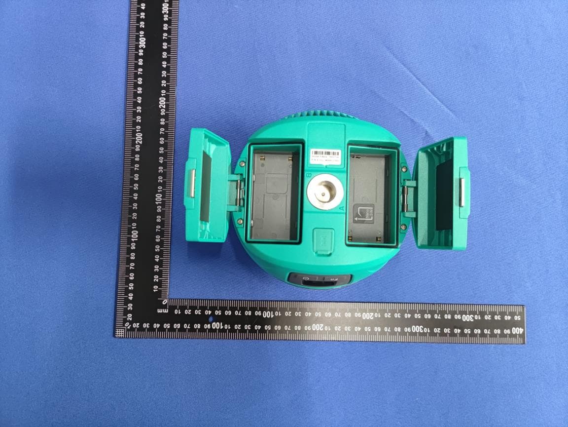
FCCID: 2A3MU-F8 FCCID: 2A3MU-F8 UHF ANT FCCID: 2A3MU-F8 FCCID: 2A3MU-F8 FCCID: 2A3MU-F8 FCCID: 2A3MU-F8
ID Label/Location Info
4.5cm 2.5cm Label Location FCC ID: 2A3MU-F8 Shanghai EFIX Geomatics Co., Ltd. Product name: Geodetic GNSS Receiver Model No.: F8 This device complies with Part 15 of the FCC Rules. Operation is subject to the following two conditions: (1) this device may not cause harmful interference, and (2) this device must accept any interference received, including interference that may cause undesired operation.
Internal Photos
FCCID: 2A3MU-F8 EDR ANT FCCID: 2A3MU-F8 WIFI ANT FCCID: 2A3MU-F8 FCCID: 2A3MU-F8 FCCID: 2A3MU-F8 FCCID: 2A3MU-F8 FCCID: 2A3MU-F8 FCCID: 2A3MU-F8 FCCID: 2A3MU-F8 FCCID: 2A3MU-F8 FCCID: 2A3MU-F8 FCCID: 2A3MU-F8 FCCID: 2A3MU-F8 FCCID: 2A3MU-F8 FCCID: 2A3MU-F8 FCCID: 2A3MU-F8 FCCID: 2A3MU-F8 FCCID: 2A3MU-F8 FCCID: 2A3MU-F8
RF Exposure Info
FCC ID: 2A3MU-F8 Prediction of MPE at a given distance 1. Limits The criteria listed in the following table shall be used to evaluate the environment impact of human exposure to radio frequency (RF) radiation as specified in 1.1307(b) 2. Test Procedure Equation from page 18 of OET Bulletin 65, Edition 97-01 Where: S = power density P = power input to the antenna G = numeric gain of the antenna in the direction of interest relative to an isotropic radiator R = distance to the centre of radiation of the antenna FCC ID: 2A3MU-F8 3. Result Worse case is as below: Mode Frequency (MHz) Prediction distance (cm) RF output power MPE (mW/cm 2 ) Limit (mW/cm 2 ) MPE Test Exclusion dBm mW EDR 2402 50 2.138 1.6361 0.00006 1 Yes 2.4GWIFI 2462 50 18.562 71.8125 0.00218 1 Yes 5GWIFI BAND1 5210 50 8.696 7.4063 0.00038 1 Yes UHF 440.000 50 30.227 1053.6588 0.08425 0.3133 Yes Maximum Simultaneous transmission MPE Ratios for EDR+2.4GWIFI+UHF: Max MPE ratio EDR /Limit Max MPE ratio WIFI /Limit Max MPE ratio UHF /Limit ∑MPE ratios Limit Result 0.00006 0.00218 0.08425 0.08649 1 PASS EDR Antenna Gain: 0.5dBi, 1.12(numeric) 2.4GWIFI Antenna Gain: -0.2dBi, 0.95(numeric) 5GWIFI Antenna Gain: 2.1dBi, 1.62(numeric) UHF Antenna Gain: 4dBi, 2.51(numeric) Meet MPE requirements, RF Exposure evaluation is not required.
Test Report
OEM GNSS Antenna HX-CSX178A Key Features Supports GPS, GLONASS, Beidou, Galileo, QZSS Supports WiFi (2.4G/5.8G) /BT Anti-electromagnetic interference, tracking in complex environments Powerful system compatibility, easy for machine integration HX-CSX178A is a embedded full frequency GNSS antenna covering GPS, GLONASS, BDS, GALILEO, and QZSS. It is also compatible with the WiFi and bluetooth, meeting the demand for multi-system compatibility in current survey devices. It can be widely used in various applications such as geodetic surveying, marine surveying, channel surveying, dredging surveying, seismic monitoring, bridge deformation monitoring, landslide monitoring, and port container operations. HIGHLY INTEGRATED ANTENNA FOR EASY INTEGRATION HX-CSX215A integrates GNSS antenna and WiFi/BT into one compact enclosure, greatly simplifying RTK integration. Deep optimization has been carried out for the isolation between antennas of various systems, systematically addressing the electromagnetic compatibility issues that have long troubled RTK receivers. RELIABLE STRUCTURE FOR STABLE PERFORMANCE This antenna uses air dielectric and low-loss microwave board materials. The overall weight is reduced, the structure is more robust, and the electrical performance becomes more stable and reliable. STRONG ANTI-INTERFERENCE PERFORMANCE The advanced LNA (Low Noise Amplifier) excels in improved signal filtering and out-of-band rejection, perfectly restraining unwanted electromagnetic interferences. With strong multi-path reduction capacity for strong anti-interference performance, consistent and reliable GNSS signals can be achieved even under complicated environments such as power grids, communication base stations and broadcast stations. STABLE PHASE CENTER FOR ROBUST POSITIONING PERFORMANCE It features multi-point feeding capability, guaranteeing a reliable phase center for millimeter positioning accuracy. TRACKING IN COMPLEX ENVIRONMENTS This antenna exhibits superior high gain performance with ultralow signal loss, ensuring reliable satellite signal tracking. It also delivers wide beam width that covers wide frequencies with high marginal gain. These features guarantee robust signal availability even in low elevation, making the antenna a perfect option for complex environments with blockage, such as forests and buildings. Applicant: Shanghai EFIX Geomatics Co., Ltd. Address: Room 1137, Area D, 11th Floor, Building 1, No. 158, Shuanglian Road, Qingpu District, Shanghai OEM GNSS Antenna HX-CSX178A PERFORMANCE Signal Received GPS L1/L2/L5/L-Band BDS B1/B2/B3 GLONASS L1/L2 GALILEO E1/E2/E5a/E5b QZSS:L1/L2/L5/L6 BT1/WiFi1:2.4G BT2/WIFI2:2.4G/5.8G Nominal Impedance 50 Ω Polarization RHCP Axial Ratio ≤3dB Azimuth Coverage 360° Azimuth Coverage ≤2.0 Peak Gain GNSS: 5.6dBi BT:0.5dBi 2.4GWIFI:-0.2dBi 5GWIFI:2.1dBi Phase Center Deviation ±2mm LOW NOISE AMPLIFIER LNA Gain 30±2dB Noise Figure ≤2dB VSWR ≤2.0 Passband Ripple ±2dB Passband Ripple +3.3~+12VDC Operation Current ≤45mA Group Delay Ripple ≤5ns MECHANICAL Dimensions Φ115*H15.4mm Connector GNSS: MMCX WiFi: IPEX ENVIRONMENTAL Operating Temperature -40°C~+85°C Storage Temperature -55°C~+85°C Humidity 95% non-condensing Specifications OEM GNSS Antenna HX-CSX178A GNSS Antenna Performance Frequency (MHz) 1176 1206 1227 1268 1542 1561 1575 1606 Gain (dBi) 2.3 3.9 4.7 4.7 4.5 5.6 5.6 4.8 1176MHz 1227MHz 1268MHz 1542MHz OEM GNSS Antenna HX-CSX178A 1561MHz 1575MHz 1606MHz BT Antenna Performance Frequency (MHz) 2400 2410 2420 2430 2440 2450 2460 2470 2480 2490 2500 Gain (dBi) -5.1 -3.6 -1.1 -0.2 0.2 0.5 -0.1 -1.3 -2.8 -5.8 -6.1 OEM GNSS Antenna HX-CSX178A BT Antenna VSWR 2450MHz OEM GNSS Antenna HX-CSX178A WIFI Antenna Performance Frequency (MHz) 2410 2420 2430 2440 2450 2460 2470 2480 2490 2500 Gain (dBi) -4.8 -4.2 -2.3 -1.7 -0.2 -1.0 -2.0 -4.9 -5.5 -6.4 Frequency (MHz) 5100 5200 5300 5400 5500 5600 5700 5800 5900 6000 Gain (dBi) 0.7 2.1 3.8 4.3 1.8 0.2 -1.3 -2.4 -2.2 -0.9 WIFI Antenna VSWR OEM GNSS Antenna HX-CSX178A 2450MHz 5550MHz OEM GNSS Antenna HX-CSX178A TOP VIEW SIDE VIEW BOTTOM VIEW S/N:C20119000162 Model:HX-CSX178A Harxon Corporation Survey Antenna Products Structure& Phase Center Drawing (mm)(Undeclared Tolerance:±0.3mm) Label Label size: 15*30mm, the content of the label is shown as below.
Test Report
ALPHA's reports is using a digital certificate that is trusted on Adobe's official server. If there is no digital certificate or the digital certificate shows damaged in your report. Please do not accept the report. E-mail: [email protected] Tel: 4008-3008-95 Website: http://www.a-lab.cn FCC TEST REPORT FCC ID: 2A3MU-F8 On Behalf of Shanghai EFIX Geomatics Co., Ltd. Geodetic GNSS Receiver Model No.: F8 Prepared for : Shanghai EFIX Geomatics Co., Ltd. Address : Room 1137, Area D, 11th Floor, Building 1, No. 158, Shuanglian Road, Qingpu District, Shanghai Prepared By : Shenzhen Alpha Product Testing Co., Ltd. Address : Building i, No.2, Lixin Road, Fuyong Street, Bao’an District, 518103, Shenzhen, Guangdong, China Report Number : A2506320-C01-R01 Date of Receipt : July 20, 2025 Date of Test : July 20, 2025 – September 9, 2025 Date of Report : September 12, 2025 Version Number : V0 Test Result : Pass Page 2 of 102 Report No.: A2506320-C01-R01 TABLE OF CONTENTS Description Page 1. Summary of Standards And Results ..................................................................................... 6 1.1. Description of Standards and Results ............................................................ 6 2. General Information ................................................................................................................. 7 2.1. Description of Device (EUT) .......................................................................... 7 2.2. Accessories of Device (EUT) ......................................................................... 8 2.3. Tested Supporting System Details ................................................................. 8 2.4. Block Diagram of connection between EUT and simulators .......................... 8 2.5. Test Mode Description ................................................................................... 8 2.6. Test Conditions .............................................................................................. 9 2.7. Test Facility .................................................................................................... 9 2.8. Measurement Uncertainty .............................................................................. 9 2.9. Test Equipment List...................................................................................... 10 3. Maximum Peak Output power............................................................................................... 12 3.1. Limit ............................................................................................................. 12 3.2. Test Procedure ............................................................................................. 12 3.3. Test Setup .................................................................................................... 12 3.4. Test Result ................................................................................................... 12 4. Bandwidth ............................................................................................................................... 13 4.1. Limit ............................................................................................................. 13 4.2. Test Procedure ............................................................................................. 13 4.3. Test Result ................................................................................................... 13 5. Carrier Frequency Separation .............................................................................................. 24 5.1. Limit ............................................................................................................. 24 5.2. Test Procedure ............................................................................................. 24 5.3. Test Result ................................................................................................... 24 6. Number Of Hopping Channel................................................................................................ 26 6.1. Limit ............................................................................................................. 26 6.2. Test Procedure ............................................................................................. 26 6.3. Test Result ................................................................................................... 26 7. Dwell Time............................................................................................................................... 28 7.1. Test Limit ...................................................................................................... 28 7.2. Test Procedure ............................................................................................. 28 7.3. Test Result ................................................................................................... 28 8. Radiated emissions ............................................................................................................... 38 8.1. Limit ............................................................................................................. 38 8.2. Block Diagram of Test Setup ........................................................................ 39 8.3. Test Procedure ............................................................................................. 40 8.4. Test Result ................................................................................................... 40 9. RF Conducted Spurious Emissions ..................................................................................... 46 9.1. Block Diagram of Test Setup ....................................................................... 46 Page 3 of 102 Report No.: A2506320-C01-R01 9.2. Limits ........................................................................................................... 46 9.3. Test Procedure ................................…
Text truncated - open the document above for the full version.
Test Report
Page 59 of 102 Report No.: A2506320-C01-R01 Test Mode: 8DPSKLow Hopping-off Test Mode: 8DPSK-High Hopping-off Test Mode: 8DPSK-Low Hopping-on Test Mode: 8DPSK-High Hopping-on Page 60 of 102 Report No.: A2506320-C01-R01 11. BAND EDGE (CONDUCTED) 11.1.Block Diagram of Test Setup 11.2.Test Limits In any 100 kHz bandwidth outside the frequency band in which the spread spectrum or digitally modulated intentional radiator is operating, the radio frequency power that is produced by the intentional radiator shall be at least 20 dB below that in the 100 kHz bandwidth within the band that contains the highest level of the desired power, based on either an RF conducted or a radiated measurement, provided the transmitter demonstrates compliance with the peak conducted power limits. If the transmitter complies with the conducted power limits based on the use of RMS averaging over a time interval, as permitted under paragraph (b)(3) of this section, the attenuation required under this paragraph shall be 30 dB instead of 20 dB. 11.3.Test Procedure Details see the KDB 558074 D01 15.247 Meas Guidance v05r02 Place the EUT on the table and set it in transmitting mode. 11.3.1. Place the EUT on the table and set it in transmitting mode. 11.3.2. Remove the antenna from the EUT and then connect a low loss RF cable from the antenna port to the spectrum analyzer. 11.3.3. Set the spectrum analyzer as RBW=100KHz, VBW=300KHz, Sweep = auto. 11.3.4. Repeat above procedures until all frequency …
Text truncated - open the document above for the full version.
Contact Information
Applicant
Glenn Chu(Certificate manager)
[email protected]Fax: +86 755 29766001
Test Firm
Shenzhen Alpha Product Testing Co., LTD.Real Yak
Technical Specifications
| # | Rule Parts | Frequency Range | Power Output |
|---|---|---|---|
| 1 | 15C | 2.40 GHz - 2.48 GHz | 1.64 mW |
Other Applications from Shanghai EFIX Geomatics Co., Ltd
2A3MU-NBASE
Jul 13, 2026Geodetic GNSS Receiver
Equipment Class
TNB - Licensed Non-Broadcast Station Transmitter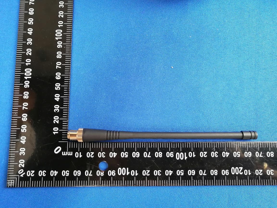
2A3MU-N50
May 13, 2026Geodetic GNSS Receiver
Equipment Class
TNB - Licensed Non-Broadcast Station Transmitter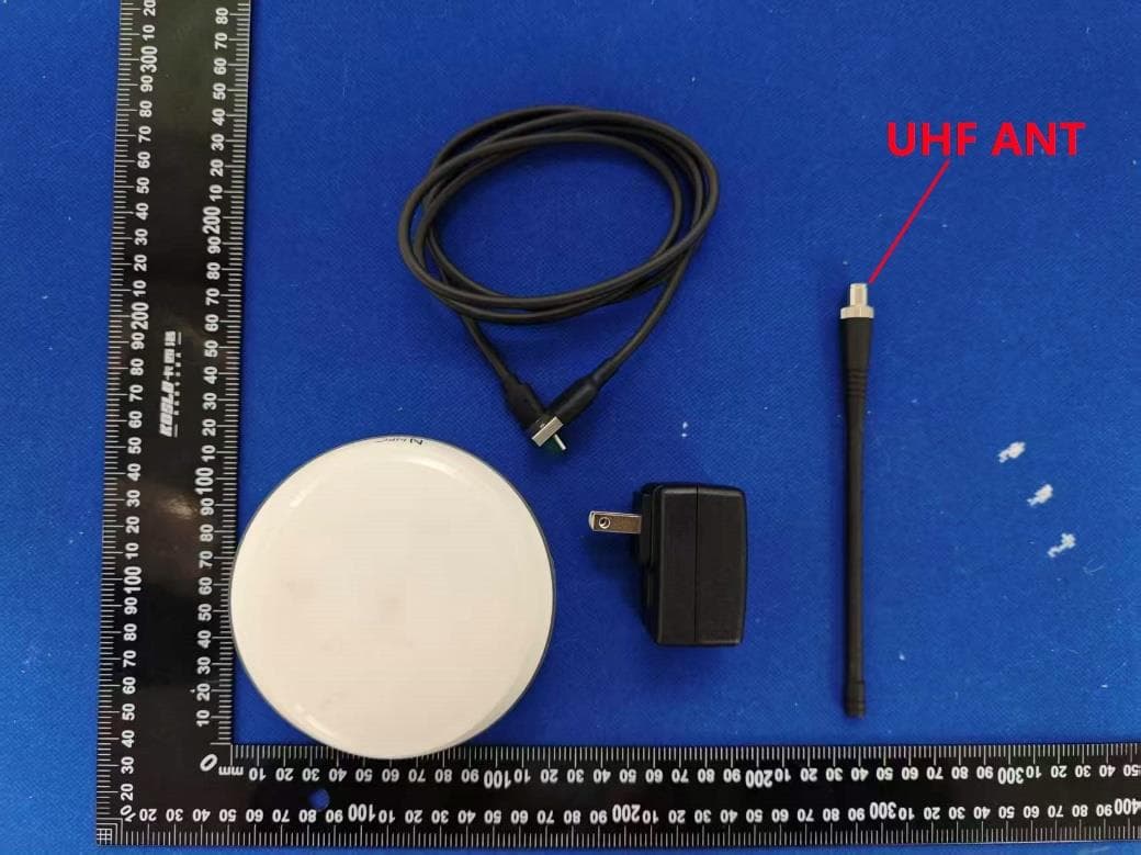
2A3MU-N30
Apr 30, 2026Geodetic GNSS Receiver
Equipment Class
DXX - Part 15 Low Power Communication Device Transmitter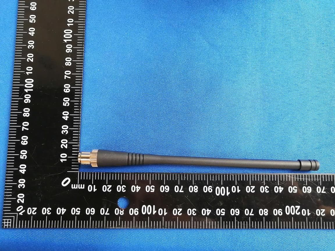
2A3MU-F8L
Sep 11, 2025Geodetic GNSS Receiver
Equipment Class
DSS - Part 15 Spread Spectrum Transmitter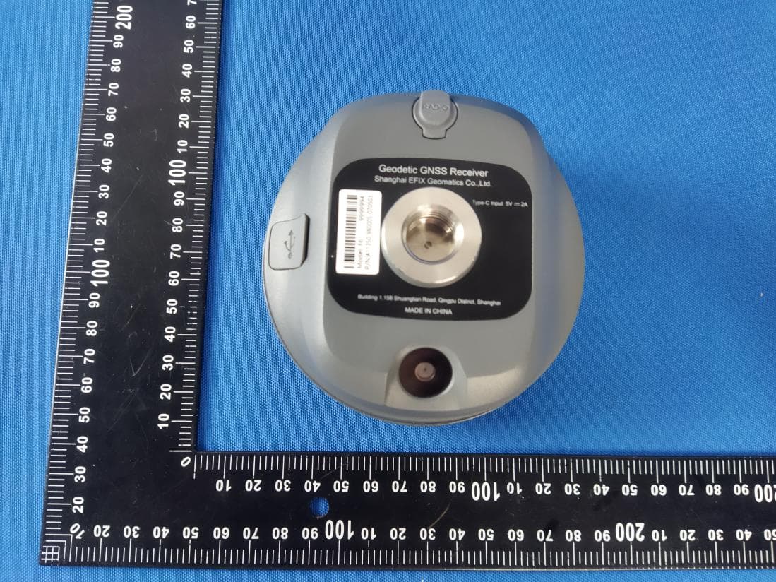
2A3MU-F6
Sep 11, 2024Geodetic GNSS Receiver
Equipment Class
DTS - Digital Transmission System