2A3NL-AIMIC-M6PROAI Conference Speakerphone
AI Speech Co.,Ltd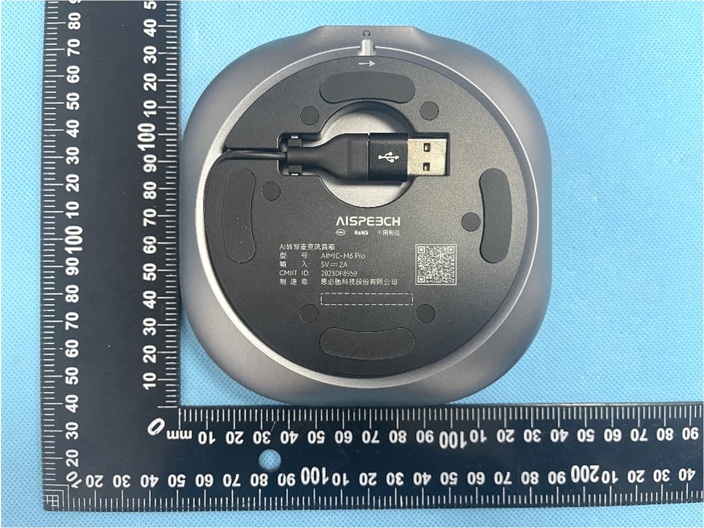
Click to zoom
Application Details
- Equipment Class
- DTS - Digital Transmission System
- Date of Grant
- Sep 16, 2023
- Application Purpose
- Original Equipment
- Date of Application
- Sep 16, 2023
- Equipment Note
- AI Conference Speakerphone
- Frequency Range
- 2402.00000000 - 2480.00000000
- Company
- AI Speech Co.,Ltd
- Country
- China
Documents & Files
Document Text
Text extracted from the exhibit documents filed with the FCC. Open a document above to read the original.
Users Manual
AI Conference Speakerphone User Manual Product introduction AIMIC-M6 Pro is an intelligent conference microphone speaker launched by AISPEECH. It’s specially designed for small collaboration rooms, small meeting rooms, open spaces, and remote office scenarios. This product integrates audio collection, amplification capabilities. It adopts a 6-unit omnidirectional microphone array and proprietary audio algorithms to achieve functions such as omnidirectional pickup within 4 meter radius, directional pickup, AI noise reduction, echo cancellation and two-way communication. It solves common pain points in meetings, such as un- clear remote communication and difficult meeting summary preparation. The directional pickup function of this product provides users with ex- clusive pickup zones, effectively blocking all sound interference from other angles,and improving remote communication efficiency. Applicable scenarios: small collaboration rooms, small meeting rooms, open spaces, and remote office. Product introduction SpeakerphoneStorage Bag User Manual Bluetooth dongle Accessories List Product introduction Buttons and indicator lights instructions Volume/Battery indicator Maximum volume Minimum volume onoff Battery>90% Battery Volume indicator Battery indicator (short press power button) ≤20% Directional Voice Pickup Press to enable/disable Status indicator light Light on: enabled Light off: disabled 1 meter 90° Product introduction Buttons and indicator lights instructions Vlume down Press to reduce volume Volume up Press to increase volume Microphone Mute Press to switch microphone status AI Button Click to start or end AI tra- n scription Tip:AI transcription function needs to be used with the Mile Memo soft- ware while the device is connected to the computer via USB. Product introduction Buttons and indicator lights instructions Bluetooth Press and hold 2 seconds to pair or disconnected Power Press and hold 3 seconds to power on or power off Status indicator light Red light breathing:bettery low White light breathing:charging White light on:bettery full or not charging *The indicator light stays on when the battery is fully charged. Status indicator light Blue light flashing:bluetooth pairing Blue light on:Bluetooth connected Headphone jack When headphone is plugged in, the device will switch audio output from the speaker to the headphone Instruction for use Ligth color instructions StatusLight color Partial green light on Power on Powen offLight off MutedRed light on Start/End AIPartial green light flashing UpgradingGreen light breathing 1.Device connection 1)Mobile phone connection The device's initial Bluetooth name is“AIMIC-M6 Pro****(the last four figures of S/N)” * Bluetooth connection After powering on device and activating Bluetooth, then turn on the Bluetooth function on your mobile phone and search for Bluetooth device named "AIMIC-M6 Pro****" for pairing and connection. Or you can enable the NFC function on your phone and tap the NFC logo area on the device to connect. The Bluetooth indicator light staying on indicates a successful connection. Instruction for use * USB connection Connect the device to computer via type-C USB data cable and you will hear a prompt tone when connected.Choose “AIMIC-M6 Pro” as input /output audio device in system setting or in the online meeting software. Tip: This device does not support direct connection to the phone using an OTG data cable. 2)Computer connection After powering on device and activating Bluetooth, then open the Bluetooth settings page on your computer system. Select this device to pair and connect. The device's Bluetooth indicator light staying on indicates a successful connection. 3)Bluetooth Dongle connection Plug in the Bluetooth dongle into the PC, conference host, or con- ference display. After powering on the device activating Bluetooth function,then open the Bluetooth settings page on the computer system. Select this device for pairing. The Bluetooth indicator light staying on indicates a successful connection. ≤ Instruction for use 3.Charging Instructions 2.Directional Pickup Note: Output power of the power supply adapter should be less than 15W.It is recommended to charge the device one hour before using it for the first time to ensure sufficient battery power. * Charging 1) When connected to computer via USB cable, the device enters charging mode regardless of whether it is powered on or off. 2) If consumers use a power adapter for power supply, please purchase one which has obtained corresponding certification. * Battery Level Check While the device is powered on, press the power button shortly to check the current battery level. 1)Battery<20%,the power button indicator light breath in red. 2)Battery 20%,the power button indicator light remain in white. 1)Press the "Directional Pickup" button to enable this function and status light will turn to green. Point the directional pickup button towards the speaker, and it will suppress all sounds out- side the directional pickup fan-shaped area, prioritizing the voice within the area. The directional pickup area has an angle of +/- 45° with the button as the center and 1meter radius. 2) Press the "Directional Pickup" button to disable this function. The light will turn off, indicating function is deactivated. Basic parameter AI Conference SpeakerphoneProduct name 5W*2Speaker 6 omnidirectional microphones Microphone 5000mAhBattery capacity Charging input5V 2A InterfaceHeadphone jack Bluetooth V5.1Bluetooth 125mm*125mm*35.5mmProduct dimensions 4 metersVoice pickup distance AI MIC-M6 ProProduct model 2)消费者若使用电源适配器供电,则应购买配套使用获得CCC认证 并 满足标准要求的电源适配器。 Brand Owner: AISpeech Technology Co., LTD. Email: RF exposure statement This equipment complies with the FCC radiation exposure limits set forth for an uncontrolled environment. This transmitter must not be co-located or operating in conjunction with any other antenna or transmitter. FCC Warning This device complies with Part 15 of the FC…
Text truncated - open the document above for the full version.
External Photos
Reference No.: WTX23X06143378W001/002 Page 2 of 14 Waltek Testing Group (Shenzhen) Co., Ltd. Http://www.waltek.com.cn EXHIBIT 2 - EUT EXTERNAL PHOTOGRAPHS EUT View 1 EUT View 2 Reference No.: WTX23X06143378W001/002 Page 3 of 14 Waltek Testing Group (Shenzhen) Co., Ltd. Http://www.waltek.com.cn EUT View 3 EUT View 4 Reference No.: WTX23X06143378W001/002 Page 4 of 14 Waltek Testing Group (Shenzhen) Co., Ltd. Http://www.waltek.com.cn EUT View 5 EUT View 6 Reference No.: WTX23X06143378W001/002 Page 5 of 14 Waltek Testing Group (Shenzhen) Co., Ltd. Http://www.waltek.com.cn EUT View 7 EUT View 8
ID Label/Location Info
Reference No.: WTX23X06143378W001/002 Page 1 of 14 Waltek Testing Group (Shenzhen) Co., Ltd. Http://www.waltek.com.cn ANNEX EXHIBIT 1 - PRODUCT LABELING Proposed FCC ID Label Format Specifications: The label shall be securely affixed to a permanently attached part of the device, in a location where it is visible or easily accessible to the user, and shall not be readily detachable. The label shall be sufficiently durable to remain fully legible and intact on the device in all normal conditions of use throughout the device’s expected lifetime. Proposed Label Location on EUT FCC ID Label Location
Internal Photos
Reference No.: WTX23X06143378W001/002 Page 6 of 14 Waltek Testing Group (Shenzhen) Co., Ltd. Http://www.waltek.com.cn EXHIBIT 3 - EUT INTERNAL PHOTOGRAPHS EUT Housing and Board View 1 Solder Board-Component View 1 Reference No.: WTX23X06143378W001/002 Page 7 of 14 Waltek Testing Group (Shenzhen) Co., Ltd. Http://www.waltek.com.cn Solder Board-Component View 2 Solder Board-Component View 3 Reference No.: WTX23X06143378W001/002 Page 8 of 14 Waltek Testing Group (Shenzhen) Co., Ltd. Http://www.waltek.com.cn Solder Board-Component View 4 Solder Board-Component View 5 Reference No.: WTX23X06143378W001/002 Page 9 of 14 Waltek Testing Group (Shenzhen) Co., Ltd. Http://www.waltek.com.cn Solder Board-Component View 6 Solder Board-Component View 7 Reference No.: WTX23X06143378W001/002 Page 10 of 14 Waltek Testing Group (Shenzhen) Co., Ltd. Http://www.waltek.com.cn Solder Board-Component View 8 Solder Board-Component View 9 Reference No.: WTX23X06143378W001/002 Page 11 of 14 Waltek Testing Group (Shenzhen) Co., Ltd. Http://www.waltek.com.cn Antenna View BT Ant.
RF Exposure Info
1. RF Exposure Requirements 1.1 General Information Client Information Applicant: AI Speech Co.,Ltd. Address of applicant: NO.14 Building,Ascendas iHub Suzhou, No.388 Xin Ping Street Suzhou,Jiangsu,China Manufacturer: AI Speech Co.,Ltd. Address of manufacturer: NO.14 Building,Ascendas iHub Suzhou, No.388 Xin Ping Street Suzhou,Jiangsu,China General Description of EUT: Product Name: AI Conference Speakerphone Trade Name AISPEECH Model No.: AIMIC-M6 Pro Adding Model(s): AIMIC-M6 Rated Voltage: Battery DC 3.7V Battery Capacity: 5000mAh Adapter Model: / FCC ID: 2A3NL-AIMIC-M6PRO Equipment Type: Portable device Technical Characteristics of EUT: Bluetooth(BLE mode) Bluetooth Version: V5.1 (BLE mode) Frequency Range: 2402-2480MHz RF Output Power: -1.11dBm (Conducted) Data Rate: 1Mbps Modulation: GFSK Quantity of Channels: 40 Channel Separation: 2MHz Type of Antenna: Chip antenna Antenna Gain: 1.75dBi Bluetooth(BR/EDR mode) Bluetooth Version: V5.1 (BR/EDR mode) Frequency Range: 2402-2480MHz RF Output Power: 0.68dBm (Conducted) Data Rate: 1Mbps, 2Mbps, 3Mbps Modulation: GFSK, π/4 DQPSK, 8DPSK Quantity of Channels: 79 Channel Separation: 1MHz Type of Antenna: Chip antenna Antenna Gain: 1.75dBi 1.2 RF Exposure Exemption According to §1.1307(b)(3) and KDB 447498 D04 Interim General RF Exposure Guidance v01, system operating under the provisions of this section shall be operating in a manner that the public is not exposed to radio frequency energy level in excess limit for maximum permissible exposure. Option A: FCC Rule Part 1.1307 (b)(3)(i)(A):The available maximum time-averaged power is no more than 1mW, regardless of separation distance. Option B: FCC Rule Part 1.1307 (b)(3)(i)(B): The available maximum time-averaged power or effective radiated power (ERP), whichever is greater, is less than or equal to the threshold P th (mW) described in the following formula. P th is given by: Option C: FCC Rule Part 1.1307 (b)(3)(i)(C): The minimum separation distance (R in meters) from the body of a nearby person for the frequency (f in MHz) at which the source operates, the ERP (watts) is no more than the calculated value prescribed for that frequency. R must be at least λ/2π, where λ is the free-space operating wavelength in meters. Single RF Sources Subject to Routine Environmental Evaluation RF Source frequency (MHz) Threshold ERP (watts) 0.3-1.34 1,920 R 2 1.34-30 3,450 R 2 /f 2 30-300 3.83 R 2 300-1,500 0.0128 R 2 f 1,500-100,000 19.2R 2 For Multiple RF sources: FCC Rule Part 1.1307(b)(3)(ii): (A) The available maximum time-averaged power of each source is no more than 1 mW and there is a separation distance of two centimeters between any portion of a radiating structure operating and the nearest portion of any other radiating structure in the same device, except if the sum of multiple sources is less than 1 mW during the time-averaging period, in which case they may be treated as a single source (separation is not required). (B) In the case of fixed RF sources operating in the same time-averaging period, or of multiple mobile or portable RF sources within a device operating in the same time averaging period, if the sum of the fractional contributions to the applicable thresholds is less than or equal to 1 as indicated in the following equation. 1.3 Calculated Result Radio Access Technology Prediction Frequency Output Power Antenna Gain Duty Cycle Tune-Up Time-Averaged Power ERP (MHz) (dBm) (dBi) (%) (dBm) (dBm) Bluetooth 2402 0.68 1.75 100 1.00 0.60 Frequency Option Min. Distance Max. Power Exposure Limit Ratio Result (MHz) (cm) (dBm) (mW) (mW) Pass/Fail 2402 B 0.5 1.00 1.26 2.788 0.45 Pass Note: 1. Time-Averaged Power=Output Power * Duty Cycle; ERP= Time-Averaged Power+ Antenna gain-2.15dB 2. Option A, B and C refers as clause 1.2. 3. For option B, Max (time-averaged power, effective radiated power (ERP)) converts to Max. Power. For option C, ERP converts to Max. Power; 4. For option B, P th (mW) converts to Exposure Limit (mW); For option C, ERP (W) converts to Exposure Limit (mW). 5. Ratio= Tune-Up ERP (mW)/ Exposure Limit (mW) Mode for Simultaneous Multi-band Transmission: Radio Access Technology Ratio 1 Ratio 2 Simultaneous Ratio Limit Result Pass/Fail -- -- -- -- -- -- Result: Pass
Test Report
Waltek Testing Group (Shenzhen) Co., Ltd. Http://www.waltek.com.cn Page 1 of 38 TEST REPORT Reference No. ....................: WTX23X06143378W002 FCC ID ............................... .: 2A3NL-AIMIC-M6PRO Applicant .......................... .: AI Speech Co.,Ltd. Address ............................ .: NO.14 Building,Ascendas iHub Suzhou, No.388 Xin Ping Street Suzhou, Jiangsu,China Manufacturer .................... .: The same as Applicant Address ............................ .: The same as Applicant Product Name .................. .: AI Conference Speakerphone Model No.. ......................... .: AIMIC-M6 Pro Standards ......................... .: FCC Part 15.247 Date of Receipt sample ... .: 2023-06-30 Date of Test....................... .: 2023-06-30 to 2023-09-06 Date of Issue .................... .: 2023-09-06 Test Report Form No. ...... . : WTX_Part 15_247W Test Result ........................ .: Pass Remarks: The results shown in this test report refer only to the sample(s) tested, this test report cannot be reproduced, except in full, without prior written permission of the company. The report would be invalid without specific stamp of test institute and the signatures of approver. Prepared By: Waltek Testing Group (Shenzhen) Co., Ltd. Address: 1/F., Room 101, Building 1, Hongwei Industrial Park, Liuxian 2nd Road, Block 70 Bao'an District, Shenzhen, Guangdong, China Tel.: +86-755-33663308 Fax.: +86-755-33663309 Email: [email protected] Tested by: Approved by: Gala Wang Silin Chen Reference No.: WTX23X06143378W002 Waltek Testing Group (Shenzhen) Co., Ltd. Http://www.waltek.com.cn Page 2 of 38 TABLE OF CONTENTS 1. GENERAL INFORMATION .................................................................................................................................... 4 1.1 PRODUCT DESCRIPTION FOR EQUIPMENT UNDER TEST (EUT) ......................................................................... 4 1.2 TEST STANDARDS ................................................................................................................................................. 5 1.3 TEST METHODOLOGY ........................................................................................................................................... 5 1.4 TEST FACILITY ...................................................................................................................................................... 5 1.5 EUT SETUP AND TEST MODE .............................................................................................................................. 6 1.6 MEASUREMENT UNCERTAINTY ............................................................................................................................. 7 1.7 TEST EQUIPMENT LIST AND DETAILS ................................................................................................................... 8 2. SUMMARY OF TEST RESULTS ......................................................................................................................... 11 3. ANTENNA REQUIREMENT ................................................................................................................................. 12 3.1 STANDARD APPLICABLE ..................................................................................................................................... 12 3.2 EVALUATION INFORMATION ................................................................................................................................ 12 4. POWER SPECTRAL DENSITY ........................................................................................................................... 13 4.1 STANDARD APPLICABLE ..................................................................................................................................... 13 4.2 TEST SETUP BLOCK DIAGRAM ........................................................................................................................... 13 4.3 TEST PROCEDURE .............................................................................................................................................. 13 4.4 SUMMARY OF TEST RESULTS/PLOTS ................................................................................................................. 13 5. DTS BANDWIDTH ................................................................................................................................................. 14 5.1 STANDARD APPLICABLE ..................................................................................................................................... 14 5.2 TEST SETUP BLOCK DIAGRAM ........................................................................................................................... 14 5.3 TEST PROCEDURE .............................................................................................................................................. 14 5.4 SUMMARY OF TEST RESULTS/PLOTS ................................................................................................................. 14 6. RF OUTPUT POWER ............................................................................................................................................ 15 6.1 STANDARD APPLICABLE ..................................................................................................................................... 15 6.2 TEST SETUP BLOCK DIAGRAM ........................................................................................................................... 15 6.3 TEST PROCEDURE .............................................................................................................................................. 15 6.4 SUMMARY OF TEST RESULTS/PLOTS ................................................................................................................. 15 7. FIELD STRENGTH OF SPURIOUS EMISSIONS ...........................................…
Text truncated - open the document above for the full version.
Test Report
SPECIFICATION FOR APPROVAL CUSTOMER : CUSTOMER’S P/N : PART NUMBER : WAN3216F245C04 DESCRIPTION : Chip Antenna 3216 L Ant 2.45G Type 04 VERSION : V1.5 ISSUE DATE : 2023/09/14 CUSTOMER APPROVED R&D CENTER APPROVAL CHECKED DRAWN Ray Tennyson Snow OneWave Electronic Co., Ltd. 1F, No. 151, Li Gong Street, Beitou District, Taipei City 11261, Taiwan TEL:+886 2 2898-2220 FAX:+886 2 2898-5055 2/11 ONEWAVE TECHNOLOGY CO., LTD. 3216 Chip antenna For Bluetooth / WLAN Applications Dimension (mm) L 3.23 ± 0.20 W 1.66 ± 0.20 T 0.45 ± 0.20 P/N: WAN3216F245C04 3/11 ONEWAVE TECHNOLOGY CO., LTD. Part Number Information WAN 3216 F 245 C 04 A B C D E F A Product Series Antenna B Dimension L x W 3.2 x 1.6mm (±0.2mm) C Material High K material D Working Frequency 2.4 ~ 2.5GHz E Feeding mode PIFA & Single Feeding F Antenna type Type = 04 1. Electrical Specification Remark : Bandwidth & Peak Gain was measured under evaluation board of next page Specification Part Number WAN3216F245C04 Central Frequency 2450 MHz Bandwidth 120 (Min.) MHz Return Loss -6.5 (Max) dB Peak Gain 1.75 dBi Impedance 50 Ohm Operating Temperature -40~+110 °C Maximum Power 4 W Resistance to Soldering Heats 10 ( @ 260°C) sec. Polarization Linear Azimuth Beamwidth Omni-directional Termination Cu / Sn (Leadless) 4/11 ONEWAVE TECHNOLOGY CO., LTD. 2. Recommended PCB Pattern Evaluation Board Dimension 2 nd Evaluation Board Dimension Suggested Matching Circuit Important information: It is recommended to use highly accurate inductors ±0.1~0.3nH and capacitance ±0.1pF for matching components. 5/11 ONEWAVE TECHNOLOGY CO., LTD. Layout Dimensions in Clearance area( Size=5.9*5.0mm) FootPrint (Unit : mm) ◆ 2 nd Layout Dimensions in Clearance area( Size=8.0*3.0mm) Matching Circuit 50 ohm transmission Line 6/11 ONEWAVE TECHNOLOGY CO., LTD. 3. Measurement Results Return Loss 7/11 ONEWAVE TECHNOLOGY CO., LTD. Radiation Pattern Efficiency Peak Gain Directivity 2400MHz 82.36 % 1.69 dBi 2.53 dBi 2450MHz 85.65 % 1.75 dBi 2.42 dBi 2500MHz 83.88 % 1.71 dBi 2.47 dBi Chamber Coordinate System X Z Y 8/11 ONEWAVE TECHNOLOGY CO., LTD. 4.Reliability and Test Condictions ITEM REQUIREMENTS TEST CONDITION Solderability 1. Wetting shall exceed 90% coverage 2. No visible mechanical damage Pre-heating temperature:150°C/60sec. Solder temperature:230±5°C Duration:4±1sec. Solder:Sn-Ag3.0-Cu0.5 Flux for lead free: rosin Solder heat Resistance 1. No visible mechanical damage 2. Central Freq. change :within ± 6% 10 ± 0.5 sec. 60 sec . . T E M P ( °C ) 150 °C 2 6 0 °C Pre-heating temperature:150°C/60sec. Solder temperature:260±5°C Duration:10±0.5sec. Solder:Sn-Ag3.0-Cu0.5 Flux for lead free: rosin Component Adhesion (Push test) 1. No visible mechanical damage The device should be reflow soldered(230±5°C for 10sec.) to a tinned copper substrate A dynometer force gauge should be applied the side of the component. The device must with-ST-F 0.5 Kg without failure of the termination attached to component. Component Adhesion (Pull test) 1. No visible mechanical damage Insert 10cm wire into the remaining open eye bend ,the ends of even wire lengths upward and wind together. Terminal shall not be remarkably damaged. Thermal shock 1. No visible mechanical damage 2. Central Freq. change :within ±6% Phase Temperature(°C) Time(min) 1 +110±5°C 30±3 2 Room Temperature Within 3sec 3 -40±2°C 30±3 4 Room Temperature Within 3sec +110°C=>30±3min -40°C=>30±3min Test cycle:10 cycles The chip shall be stabilized at normal condition for 2~3 hours before measuring. Resistance to High Temperature 1. No visible mechanical damage 2. Central Freq. change :within ±6% 3. No disconnection or short circuit. Temperature: +110±5°C Duration: 1000±12hrs The chip shall be stabilized at normal condition for 2~3 hours before measuring. Resistance to Low Temperature 1. No visible mechanical damage 2. Central Freq. change :within ±6% 3. No disconnection or short circuit. Temperature:-40±5°C Duration: 1000±12hrs The chip shall be stabilized at normal condition for 2~3 hours before measuring. Humidity 1. No visible mechanical damage 2. Central Freq. change :within ±6% 3. No disconnection or short circuit. Temperature: 40±2°C Humidity: 90% to 95% RH Duration: 1000±12hrs The chip shall be stabilized at normal condition for 2~3 hours before measuring. 4±1 sec. 60sec TEMP (°C) 150°C 230°C 9/11 ONEWAVE TECHNOLOGY CO., LTD. 5.Soldering and Mounting Mildly activated rosin fluxes are preferred. The minimum amount of solder can lead to damage from the stresses caused by the difference in coefficients of expansion between solder, chip and substrate. The terminations are suitable for all wave and re-flow soldering systems. If hand soldering cannot be avoided, the preferred technique is the utilization of hot air soldering tools. Recommended temperature profiles for re-flow soldering in Figure 1. Products attachment with a soldering iron is discouraged due to the inherent process control limitations. In the event that a soldering iron must be employed the following precautions are recommended. ‧Preheat circuit and products to 150°C ‧Never contact the ceramic with the iron tip ‧Use a 20 watt soldering iron with tip diameter of 1.0mm ‧280°C tip temperature (max) ‧1.0mm tip diameter (max) ‧Limit soldering time to 3 sec. SOLDERING COOLING NATURAL PRE-HEATING TEMPERATURE(°C) 60~120 s 10s max. 30~60s 250~260 230 180 150 TIME(sec.) Reflow Soldering SOLDERING COOLING NATURAL PRE-HEATING TEMPERATURE(°C) within 3s Gradual cooling 150 TIME(sec.) Iron Soldering Over 60s 350 300 10/11 ONEWAVE TECHNOLOGY CO., LTD. 6.Packaging Information Tape Specification: Reel Specification: (7’’, Φ180 mm) Tape Width(mm) A(mm) B(mm) C(mm) D(mm) Chip/Reel(pcs) 8 9.0±0.5 60±2 13.5±0.5 178±2 3000 11/11 ONEWAVE TECHNOLOGY CO., LTD. 7.Storage and Transportation Information Storage Conditions To maintain the solderability of terminal electrodes: 1. Temperature and humidity conditions: -10~ 40°C and 30~70% RH. 2. Recommended products should be used within 6 months from th…
Text truncated - open the document above for the full version.
Test Setup Photos
Reference No.: WTX23X06143378W001/002 Page 12 of 14 Waltek Testing Group (Shenzhen) Co., Ltd. Http://www.waltek.com.cn EXHIBIT 4 - TEST SETUP PHOTOGRAPHS Conducted Emission Test Setup Radiation Emission Test Setup (Below 30MHz) Reference No.: WTX23X06143378W001/002 Page 13 of 14 Waltek Testing Group (Shenzhen) Co., Ltd. Http://www.waltek.com.cn Radiation Emission Test Setup (30MHz to 1GHz) Radiation Emission Test Setup (1GHz to 18GHz) Reference No.: WTX23X06143378W001/002 Page 14 of 14 Waltek Testing Group (Shenzhen) Co., Ltd. Http://www.waltek.com.cn Radiation Emission Test Setup (Above 18GHz) ***** END OF REPORT *****
Contact Information
Applicant
Song He(Senior Project Manager)
Test Firm
Waltek Testing Group (Shenzhen) Co., Ltd.Jandy So
Technical Specifications
| # | Rule Parts | Frequency Range | Power Output |
|---|---|---|---|
| 1 | 15C | 2.40 GHz - 2.48 GHz | 800.00 µW |
Other Applications from AI Speech Co.,Ltd
2A3NL-AINOTE-AIRH
Aug 10, 2026AINOTE Air
Equipment Class
NII - Unlicensed National Information Infrastructure TX