2A3NOT131STour Guide System
ZHENGZHOU YSAIR TECHNOLOGY CO.,LTD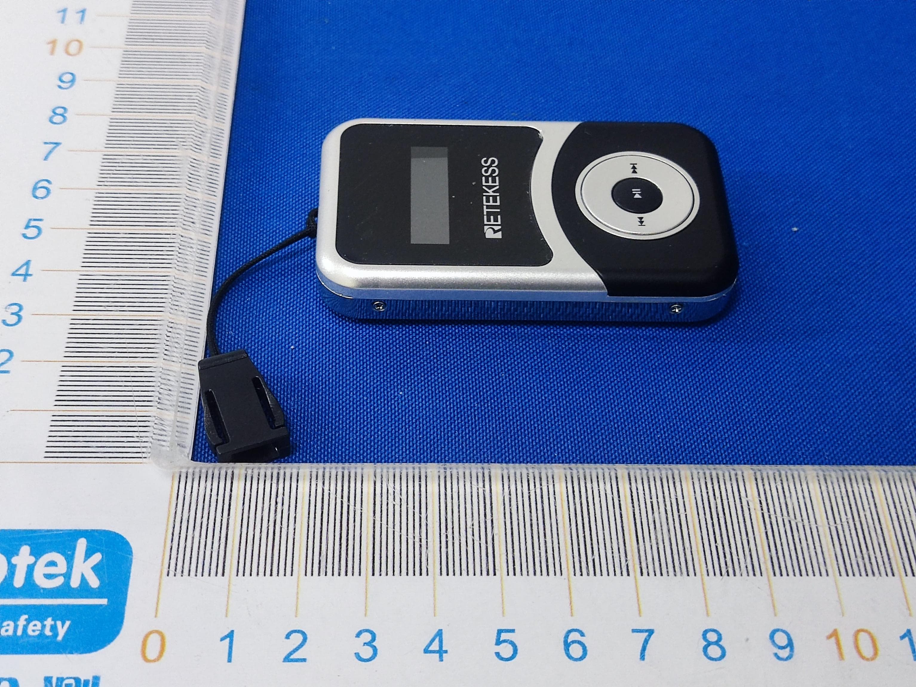
Click to zoom
Application Details
- Equipment Class
- JAB - Part 15 Class B Digital Device
- Date of Grant
- Jan 15, 2023
- Application Purpose
- Original Equipment
- Date of Application
- Jan 15, 2023
- Equipment Note
- Tour Guide System
- Country
- China
Documents & Files
Document Text
Text extracted from the exhibit documents filed with the FCC. Open a document above to read the original.
Users Manual
T130S T131S User Manual CONTENTS Transmitter Power on and power off Mute function One key shutdown function Interface description Channel Setting Receiver Power on and power off Volume setting Channel select Precautions Precautions for using the charging box Specifications Warning DE(10-18) FR(19-27) IT(28-35) ES(36-43) .............................................................................................................. 01 ......................................................................................... 01 .......................................................................................................... 01 ................................................................................... 01 ............................................................................................... 01 .......................................................................................................01 ....................................................................................................................02 ...........................................................................................02 .........................................................................................................02 .........................................................................................................02 ..............................................................................................................02 .................................................................02 ...........................................................................................................03 .....................................................................................................................06 Transmitter 1.Power on and power off Power on: Press and hold ( ) button for 1 second to power on. Power off: Press and hold ( ) for 1 second to power off. 2.Mute function In working mode, press (>) or (+) button, the transmitter enters mute mode icon appears on the transmitter screen and icon disappears. At the same time, icon appears on the receiver screen. Press (>) or (+) button again, the transmitter will return to normal working mode, icon appears on the transmitter screen and icon disappears from receiver screen at the same time. 3.One key shutdown function In working mode, press and hold (>) or (-) button for about 5 seconds until the OFF icon flashes on the transmitter screen and icon disappears, all receivers paired with this transmitter that are within the range will be powered off. Then you can short press any key of the transmitter to exit the one key shutdown mode or long press and hold the ( ) key to power off. 4.Interface description There are two jacks at the bottom of the transmitter, the MIC microphone jack on the left and the AUX audio input jack on the right. Note: Don't insert them into the wrong interface, if you plug the mic into the AUX jack, there will be no sound. 5.Channel Setting When encountering the following situations, you will need to set the channel A.If there are two or more transmitters in use, select different channel for each to avoid interference. B.When you need to add receivers for a group (transmitter and receivers channels must be the same in each group). Channel Setting Operations A.In working mode, press and hold (>) and (<) buttons at the same time until the icon disappears on the transmitter screen, t. B.Release the (>) and (<) buttons, the transmitter will enter channel setting mode C.Press (>), (<), (+) or (-) buttons to select the desired channel ( the value could be set from 01 to 49). D.Press and hold ( ) button for 3 second until the channel ID flashes on the transmitter screen and icon disappears. E.Release the ( ) button, the transmitter enters the wireless channel synchronization mode. 1 F.Put the receivers in the power-on state close to the transmitter (within about 2 meters), the receivers will receive sync signal. Once sync successfully, the receivers channel will be changed to the same channel as the transmitter G.Press the ( ) button on the transmitter to exit channel synchronization mode. Receiver 1.Power on and power off Power on: Press and hold ( ) button for 1 second to power on. Power off: Press and hold ( ) for 1 second to power off. 2.Volume Setting In working mode, press ( ) or ( ) button to adjust the volume (the value could be set from 0 to 9 level). Note: Volume cannot be adjusted while the receiver is in signal seek mode ( icon shows on the receiver screen. If you use T130s transmitter with the old version T131 receivers, you need to use the following method to set the channel ID. 1.Wireless Channel Synchronization Setting Transmitter Setting A.In the power off mode, press and hold (>) button by your left hand, then press ( ) button for about 2s to turn on the transmitter by your right hand B.Release the ( ) button when the transmitter is powered on C.Release the (>) button when the channel ID flashed on the screen, the transmitter enters channel setting mode D.Press (>) or (<) button to select the desired channel E.Press ( ) button to confirm, the transmitter enters the wireless channel synchronization mode Then Set the Receiver F.In power off mode, insert the earphone, press and hold the ( ) button with your left hand, then press the ( ) button with your right hand to turn on the receiver. G.Release the ( ) button when the receiver is powered on H.Release the ( ) button when the channel ID shows 00 in the receiver screen, the receiver will receive sync signal. Once sync successfully, the receivers channel will be changed to the same channel as the transmitter ( Note: this step must be done under the condition that the transmitter is at the wireless channel synchronization mode) I.Turn off the transmitter, then turn on it, the transmitter will work with the paired receivers. 2 2.Manual Set Receiver Channel ID A.In power off mode, press and hold ( ) button with your right hand, …
Text truncated - open the document above for the full version.
External Photos
Code:AB-RF-05-b ExternalPhotograph Code:AB-RF-05-b Code:AB-RF-05-b Code:AB-RF-05-b
ID Label/Location Info
Label &Label location Label Size: 29.5mm*22.5mm
Internal Photos
Code:AB-RF-05-b Internal Photograph Code:AB-RF-05-b Code:AB-RF-05-b
Test Report
Report No.: 18220WC20283701 FCC ID: 2A3NOT131S Page 1 of 20 Code: AB-EMC-04-c FCC Test Report Client Name : ZHENGZHOU YSAIR TECHNOLOGY CO.,LTD Client Address : ROOM 709, SANJIANG BUILDING, NO.170 NANYANG ROAD, HUIJI DISTRICT, ZHENGZHOU HENAN, 450053 CHINA Product Name : Tour Guide System Report Date : Jan. 16, 2023 Shenzhen Anbotek Compliance Laboratory Limited Report No.: 18220WC20283701 FCC ID: 2A3NOT131S Page 2 of 20 Code: AB-EMC-04-c Contents 1. General Information ............................................................................................................................... 4 1.1. Client Information ........................................................................................................................ 4 1.2. Description of Device (EUT) ....................................................................................................... 4 1.3. Auxiliary Equipment Used During Test ........................................................................................ 5 1.4. Description of Test Mode ............................................................................................................ 5 1.5. Test Summary ............................................................................................................................. 5 1.6. Test Equipment List ..................................................................................................................... 6 1.7. Measurement Uncertainty ........................................................................................................... 7 1.8. Description of Test Facility .......................................................................................................... 7 2. Power Line Conducted Emission Test................................................................................................... 8 2.1. Test Standard and Limit .............................................................................................................. 8 2.2. Test Setup ................................................................................................................................... 8 2.3. Test Procedure ............................................................................................................................ 9 2.4. Test Results ................................................................................................................................. 9 3. Radiated Emission Te s t (Below 1 GHz) .............................................................................................. 12 3.1. Test Standard and Limit ............................................................................................................ 12 3.2. Test Setup ................................................................................................................................. 13 3.3. Test Procedure .......................................................................................................................... 13 3.4. Test Results ............................................................................................................................... 14 4. Radiated Emission Te s t (Above 1GHz) ............................................................................................... 17 4.1. Test Standard and Limit ............................................................................................................ 17 4.2. Test Setup ................................................................................................................................. 17 4.3. Test Procedure .......................................................................................................................... 18 4.4. Test Results ............................................................................................................................... 18 APPENDIX I -- TEST SETUP PHOTOGRAPH ....................................................................................... 20 APPENDIX II -- EXTERNAL PHOTOGRAPH ......................................................................................... 20 APPENDIX III -- INTERNAL PHOTOGRAPH ......................................................................................... 20 Report No.: 18220WC20283701 FCC ID: 2A3NOT131S Page 3 of 20 Code: AB-EMC-04-c TEST REPORT Applicant : ZHENGZHOU YSAIR TECHNOLOGY CO.,LTD Manufacturer : ZHENGZHOU YSAIR TECHNOLOGY CO.,LTD Product Name : Tour Guide System Model No. : T131S Trade Mark : RETEKESS Rating(s) : Input: 5V⎓1A(with DC 3.7V, 900mAh Battery inside) Test Standard(s) : FCC 47 CFR Part 15 Subpart B: 2022 Test Method(s) : ANSI C63.4-2014 The device described above is tested by Shenzhen Anbotek Compliance Laboratory Limited To determine the maximum emission levels emanating from the device. The maximum emission levels are compared to the FCC 47 CFR Part 15 Subpart B limits both radiated and conducted emissions. The measurement results are contained in this test report and Shenzhen Anbotek Compliance Laboratory Limited Is assumed full responsibility for the accuracy and completeness of these measurements. This report applies to above tested sample only. This report shall not be reproduced in part without written approval of Shenzhen Anbotek Compliance Laboratory Limited Date of receipt Dec. 14, 2022 Date of Test Dec. 14, 2022 ~Jan. 03, 2023 Prepared By (Nianxiu Chen) Approved & Authorized Signer (Kingkong Jin) Report No.: 18220WC20283701 FCC ID: 2A3NOT131S Page 4 of 20 Code: AB-EMC-04-c 1. General Information 1.1. Client Information Applicant : ZHENGZHOU YSAIR TECHNOLOGY CO.,LTD Address : ROOM 709, SANJIANG BUILDING, NO.170 NANYANG ROAD, HUIJI DISTRICT, ZHENGZHOU HENAN, 450053 CHINA Manufacturer : ZHENGZHOU YSAIR TECHNOLOGY CO.,LTD Address : ROOM 709, SANJIANG BUILDING, NO.170 NANYANG ROAD, HUIJI DISTRICT, ZHENGZHOU HENAN, 450053 CHINA 1.2. Description of Device (EUT) Product Name : Tour Guide System Model …
Text truncated - open the document above for the full version.
Test Setup Photos
Code:AB-RF-05-b TestSetupPhotograph PhotoofPowerLineConductedEmissionTest PhotoofRadiationEmissionTest(Below1GHz) Code:AB-RF-05-b PhotoofRadiationEmissionTest(Above1GHz)
Contact Information
Applicant
Weidong Shen(General Manager)
Test Firm
Shenzhen Anbotek Compliance Laboratory LimitedJeff Zhu
Technical Specifications
| # | Rule Parts | Frequency Range | Power Output |
|---|---|---|---|
| 1 | 15B | - | - |
Other Applications from ZHENGZHOU YSAIR TECHNOLOGY CO.,LTD
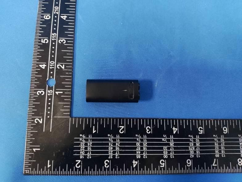
2A3NOTG103
Oct 07, 2024Wireless Lavalier Microphone
Equipment Class
DXX - Part 15 Low Power Communication Device Transmitter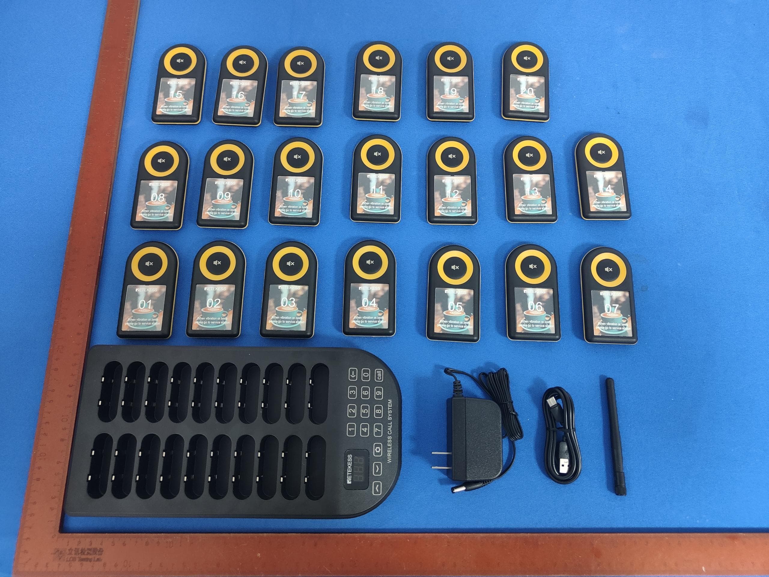
2A3NOTD169
Sep 18, 2024Queue Wireless Calling System
Equipment Class
DSC - Part 15 Security/Remote Control Transmitter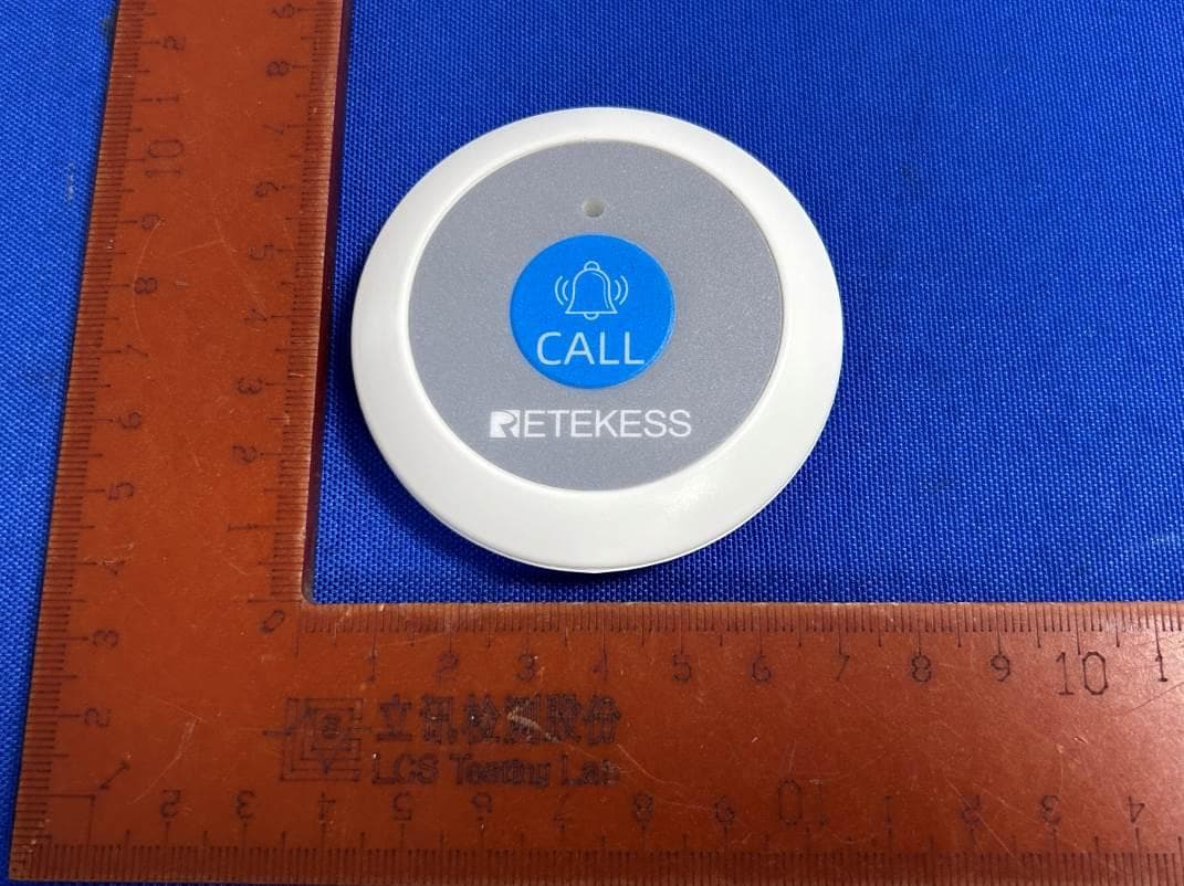
2A3NOTH009
Aug 20, 2024Pager
Equipment Class
DSC - Part 15 Security/Remote Control Transmitter
2A3NOTD113
Aug 16, 2024Paging Watch
Equipment Class
DSC - Part 15 Security/Remote Control Transmitter
2A3NOTR640
Jul 17, 2024Internet Radio
Equipment Class
DTS - Digital Transmission System