2A3O2-PITCHREMOTEPitchRemote
JHCF, LLC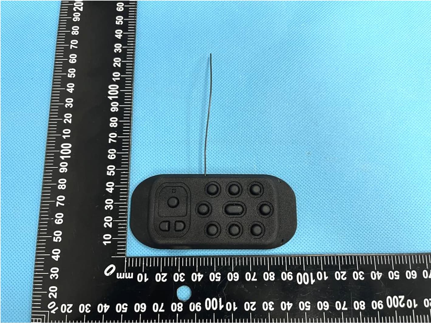
Click to zoom
Application Details
- Equipment Class
- DXX - Part 15 Low Power Communication Device Transmitter
- Date of Grant
- Sep 04, 2023
- Application Purpose
- Original Equipment
- Date of Application
- Sep 04, 2023
- Equipment Note
- PitchRemote
- Frequency Range
- 915.25000000 - 927.75000000
- Company
- JHCF, LLC
- Country
- United States
Documents & Files
Document Text
Text extracted from the exhibit documents filed with the FCC. Open a document above to read the original.
Users Manual
1 PitchCom SystemManual Welcome to the ClockComSystem-the world’s best and most secure baseball communication system for transmitting signals to an official indicating the expiration of a timer. The ClockCom System consists of two components-a transmitter (also, the “PitchRemote”) and a receiver (also, the “PitchClock”). At the end of a timed period, the transmitter receives a signal from the timer and wirelessly transmits a signal to the PitchClock receiver which produces a haptic signal to the wearer of the PitchClock receiver. 2 USING THE PITCHCOM SYSTEM-Basic Component Functions PitchClock Receiver The receiver is shown in Figure 1. The receiver has a micro-USB port for charging and updating firmware. A charge LED glows red when the receiver is charging. The receiver is turned on by depressing an on/off switch, which is covered by shrink wrap. The receiver is turned off by depressing and holding the on/off switch. In operation, after being turned on, upon receiving a signal through the antenna from the transmitter, the receiver activates the vibration motor for a given amount of time. The wearer of the receiver can perceive this activation as a haptic signal or buzz. Micro-USB Port Charge LED On/Off Switch On/Off LED Antenna Figure 1 Vibration Motor 3 Transmitter The PitchRemote transmitter is shown by itself in Figure 2. The transmitter does not have an on/off switch and is always ready to transmit. There are 9 pitch/location buttons, a cancel button, and two catcher volume adjustment buttons. Also, the transmitter has a micro-USB port through which the transmitter is charged and can receive firmware upgrades, an antenna wire, and a status LED above the cancel button. A white LED is also provided. The PitchRemote transmitter is connected to a clock timer. When the clock period reaches a certain time, such as zero seconds, the clock timer sends an expiration signal to the transmitter through a cable connecting the clock timer and the micro-USB port of the transmitter. When the expiration signal is received, the transmitter then wirelessly transmits a signal to the receiver that then activates the vibration motor, as described above. System Maintenance The PitchCom System components are designed to be very low maintenance. The receivers are charged through theirmicro-USB ports. Firmware upgrades and audio tracks are provided through the micro-USB ports. Each battery charge should last at least 6 hours of continuous receiver use. We recommend recharging the receivers after each game in which the units are used. Any micro-USB plug and standard wall transformer can be used to charge the receivers. The PitchRemotetransmitter is charged through the micro-USB port. 1 2 3 4 5 6 7 8 9 Cancel VdnVup Figure 2 Micro-USB 4 PitchClock FCC Compliance Statement This device complies with part 15 of the FCC Rules. Operation is subject to the following two conditions: (1) this device may not cause harmful interference, and (2) this device must accept any interference received, including interference that may cause undesired operation. CAUTION: The grantee is not responsible for any changes or modifications not expressly approved by the party responsible for compliance. Such modifications could void the user’s authority to operate the equipment. NOTE: This equipment has been tested and found to comply with the limits for a Class B digital device, pursuant to part 15 of the FCC Rules. These limits are designed to provide reasonable protection against harmful interference in a residential installation. This equipment generates, uses, and can radiate radio frequency energy, and if not installed and used in accordance with the instructions, may cause harmful interference to radio communications. However, there is no guarantee that interference will not occur in a particular installation. If this equipment does cause harmful interference to radio or television reception, which can be determined by turning the equipment off and on, the user is encouraged to try to correct the interference by one or more of the following measures: – Reorient or relocate the receiving antenna. – Increase the separation between the equipment and receiver. – Connect the equipment into an outlet on a circuit different from that to which the receiver is connected. – Consult the dealer or an experienced radio/TV technician for help. This equipment has been tested and meets applicable limits for radio frequency (RF) exposure. 5 PitchClockCanadian Compliance Statement This device contains license-exempt transmitter(s)/receiver(s) that comply with Innovation, Science and Economic Development Canada license-exempt RSS(s). Operation is subject to the following two conditions: (1) This device may not cause interference. (2) This device must accept any interference, including interference that may cause undesired operation of the device. L'émetteur/récepteur exempt de licencecontenu dans le présentappareilestconformeaux CNRd'Innovation, Sciences et Développementéconomique Canada applicables aux appareils radio exempts de licence. L'exploitationestautorisée aux deux conditions suivantes : 1) L'appareil ne doit pas produire de brouillage; 2) L'appareil doit accepter tout brouillageradioélectriquesubi, mêmesi le brouillageest susceptible d'encompromettre le fonctionnement. NOTE: This equipment has been tested and meets the applicable limits for radio frequency (RF) exposure under RSS-102. REMARQUE: Cetéquipement a ététesté et respecte les limitesapplicables pour l'exposition aux radiofréquences (RF) sous RSS-102. 6 PitchRemote FCC COMPLIANCE STATEMENT This device complies with part 15 of the FCC Rules. Operation is subject to the following two conditions: (1) this device may not cause harmful interference, and (2) this device must accept any interference received, including interference that may cause undesired operation. CAUTION: The grantee is not responsible for any changes or modifications not expressly approved by the party responsible f…
Text truncated - open the document above for the full version.
Attestation Statements
JHCF, LLC 6133 E. Exeter Blvd Scottsdale, AZ 85251 Date: 07/13/23 Federal Communications Commission Authorization and Evaluation Division 7435 Oakland Mills Road Columbia, MD 21046 FCC ID: 2A3O2-PITCHREMOTE Attestation Statements Part 2.911(d)(5)(ii) Filing To whom it may concern, JHCF, LLC certifies that, as of the date of the filing of the application, JHCF, LLC is not identified on the Covered List (as a specifically named entity or any of its subsidiaries or affiliates) as an entity producing “covered” equipment. Sincerely,
Attestation Statements
JHCF, LLC 6133 E. Exeter Blvd Scottsdale, AZ 85251 Date: 07/13/23 Federal Communications Commission Authorization and Evaluation Division 7435 Oakland Mills Road Columbia, MD 21046 FCC ID: 2A3O2-PITCHREMOTE FRN: 0031643414 US Agent – Attestation Statement / Part 2.911(d)(7) To whom it may concern, JHCF, LLC certifies that, as of the date of the filing of the application, we designate ourselves as the U.S. agent for service of process. Designated U.S. Agent Information: Name: JHCF, LLC FRN: 0031643414 Address: 6133 E. Exeter Blvd, Scottsdale, AZ 85251 Contact Person: Craig Filicetti Tel.: 602-316-8100 Email: [email protected] Sincerely, Craig Filicetti Owner
External Photos
Reference No.: WTX22X12246828W Page 2 of 10 Waltek Testing Group (Shenzhen) Co., Ltd. Http://www.waltek.com.cn EXHIBIT 2 - EUT EXTERNAL PHOTOGRAPHS EUT View 1 EUT View 2 Reference No.: WTX22X12246828W Page 3 of 10 Waltek Testing Group (Shenzhen) Co., Ltd. Http://www.waltek.com.cn EUT View 3 EUT View 4 Reference No.: WTX22X12246828W Page 4 of 10 Waltek Testing Group (Shenzhen) Co., Ltd. Http://www.waltek.com.cn EUT View 5 EUT View 6 Reference No.: WTX22X12246828W Page 5 of 10 Waltek Testing Group (Shenzhen) Co., Ltd. Http://www.waltek.com.cn EUT View 7
ID Label/Location Info
Reference No.: WTX22X12246828W Page 1 of 10 Waltek Testing Group (Shenzhen) Co., Ltd. Http://www.waltek.com.cn ANNEX EXHIBIT 1 - PRODUCT LABELING Proposed FCC ID Label Format Specifications: Label is on the product and on the product packaging. Proposed Label Location on EUT FCC ID Label Location Label on Product Packaging Label on the Product
Internal Photos
Reference No.: WTX22X12246828W Page 5 of 9 Waltek Testing Group (Shenzhen) Co., Ltd. Http://www.waltek.com.cn EXHIBIT 3 - EUT INTERNAL PHOTOGRAPHS EUT Housing and Board View 1 Solder Board-Component View 1 Reference No.: WTX22X12246828W Page 6 of 9 Waltek Testing Group (Shenzhen) Co., Ltd. Http://www.waltek.com.cn Solder Board-Component View 2 Solder Board-Component View 3 Reference No.: WTX22X12246828W Page 7 of 9 Waltek Testing Group (Shenzhen) Co., Ltd. Http://www.waltek.com.cn Solder Board-Component View 4 Antenna View
RF Exposure Info
1. RF Exposure Requirements 1.1 General Information Client Information Applicant: JHCF, LLC Address of applicant: 6133 E. Exeter Blvd, Scottsdale, AZ, 85251 Manufacturer: JHCF, LLC Address of manufacturer: 6133 E. Exeter Blvd, Scottsdale, AZ, 85251 General Description of EUT: Product Name: PitchRemote Trade Name: / Model No.: PitchRemote 2.0 Adding Model: / Rated Voltage: Charging port:DC5V Battery:DC3.7V Battery capacity: 100mAh Power Adaptor: / FCC ID: 2A3O2-PITCHREMOTE Equipment Type: Portable device Technical Characteristics of EUT: Frequency Range: 915.25-927.75MHz Max. Field Strength: 92.53dBuV/m Modulation: FSK Quantity of Channels: 51 Channel Separation: 250kHz Antenna Type: Wire Antenna Antenna Gain: 0dBi 1.2 RF Exposure Exemption According to §1.1307(b)(3) and KDB 447498 D04 Interim General RF Exposure Guidance v01, system operating under the provisions of this section shall be operating in a manner that the public is not exposed to radio frequency energy level in excess limit for maximum permissible exposure. Option A: FCC Rule Part 1.1307 (b)(3)(i)(A):The available maximum time-averaged power is no more than 1mW, regardless of separation distance. Option B: FCC Rule Part 1.1307 (b)(3)(i)(B): The available maximum time-averaged power or effective radiated power (ERP), whichever is greater, is less than or equal to the threshold P th (mW) described in the following formula. P th is given by: Option C: FCC Rule Part 1.1307 (b)(3)(i)(C): The minimum separation distance (R in meters) from the body of a nearby person for the frequency (f in MHz) at which the source operates, the ERP (watts) is no more than the calculated value prescribed for that frequency. R must be at least λ/2π, where λ is the free-space operating wavelength in meters. Single RF Sources Subject to Routine Environmental Evaluation RF Source frequency (MHz) Threshold ERP (watts) 0.3-1.34 1,920 R 2 1.34-30 3,450 R 2 /f 2 30-300 3.83 R 2 300-1,500 0.0128 R 2 f 1,500-100,000 19.2R 2 For Multiple RF sources: FCC Rule Part 1.1307(b)(3)(ii): (A) The available maximum time-averaged power of each source is no more than 1 mW and there is a separation distance of two centimeters between any portion of a radiating structure operating and the nearest portion of any other radiating structure in the same device, except if the sum of multiple sources is less than 1 mW during the time-averaging period, in which case they may be treated as a single source (separation is not required). (B) In the case of fixed RF sources operating in the same time-averaging period, or of multiple mobile or portable RF sources within a device operating in the same time averaging period, if the sum of the fractional contributions to the applicable thresholds is less than or equal to 1 as indicated in the following equation. 1.3 Calculated Result Radio Access Technology Prediction Frequency Max. Field Strength Antenna Gain Output Power Tune-Up Power ERP (MHz) (dBuV/m) (dBi) (dBm) (dBm) (dBm) SRD 915.25 92.53 0 -2.72 -2.00 -4.15 Frequency Option Min. Distance Max. Power Exposure Limit Ratio Result (MHz) (cm) (dBm) (mW) (mW) Pass/Fail 915.25 B 0.5 -2.00 0.63 8.13 0.08 Pass Note: 1. EIRP= E-104.8+20logD; Output Power=EIRP- Antenna Gain; ERP=EIRP-2.15dB 2. Option A, B and C refers as clause 1.2. 3. For option B, Max (time-averaged power, effective radiated power (ERP)) converts to Max. Power. For option C, ERP converts to Max. Power; 4. For option B, P th (mW) converts to Exposure Limit (mW); For option C, ERP (W) converts to Exposure Limit (mW). 5. Ratio= Tune-Up ERP (mW)/ Exposure Limit (mW) Mode for Simultaneous Multi-band Transmission: Radio Access Technology Ratio 1 Ratio 2 Ratio 3 Simultaneous Ratio Limit Result Pass/Fail / / / / / / / Result: Pass
Test Report
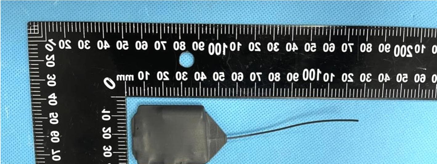
Antenna size Antenna unit 87*0.95*0.45mm
Test Report
Waltek Testing Group (Shenzhen) Co., Ltd. Http://www.waltek.com.cn Page 1 of 35 TEST REPORT Reference No. .................... : WTX22X12246828W FCC ID ................................ : 2A3O2-PITCHREMOTE Applicant ........................... : JHCF, LLC Address ............................. : 6133 E. Exeter Blvd, Scottsdale, AZ, 85251 Manufacturer ..................... : The same as Applicant Address ............................. : The same as Applicant Product Name ................... : PitchRemote Model No... ......................... : PitchRemote 2.0 Standards .......................... : FCC Part 15.249 Date of Receipt sample .... : 2022-12-07 Date of Test........................ : 2022-12-07 to 2023-02-16 Date of Issue ..................... : 2023-02-16 Test Report Form No. ....... : WTX_Part 15_249W Test Result ......................... : Pass Remarks: The results shown in this test report refer only to the sample(s) tested, this test report cannot be reproduced, except in full, without prior written permission of the company. The report would be invalid without specific stamp of test institute and the signatures of approver. Prepared By: Waltek Testing Group (Shenzhen) Co., Ltd. Address: 1/F., Room 101, Building 1, Hongwei Industrial Park, Liuxian 2nd Road, Block 70 Bao'an District, Shenzhen, Guangdong, China Tel.: +86-755-33663308 Fax.: +86-755-33663309 Email: [email protected] Tested by: Approved by: Mike Shi Silin Chen Reference No.: WTX22X12246828W Waltek Testing Group (Shenzhen) Co., Ltd. Http://www.waltek.com.cn Page 2 of 35 TABLE OF CONTENTS 1. GENERAL INFORMATION .................................................................................................................................... 4 1.1 PRODUCT DESCRIPTION FOR EQUIPMENT UNDER TEST (EUT) ......................................................................... 4 1.2 TEST STANDARDS ................................................................................................................................................. 5 1.3 TEST METHODOLOGY ........................................................................................................................................... 5 1.4 TEST FACILITY ...................................................................................................................................................... 5 1.5 EUT SETUP AND TEST MODE .............................................................................................................................. 6 1.6 MEASUREMENT UNCERTAINTY ............................................................................................................................. 7 1.7 TEST EQUIPMENT LIST AND DETAILS ................................................................................................................... 8 2. SUMMARY OF TEST RESULTS ......................................................................................................................... 11 3. ANTENNA REQUIREMENTS .............................................................................................................................. 12 3.1 STANDARD APPLICABLE ..................................................................................................................................... 12 3.2 TEST RESULT ...................................................................................................................................................... 12 4. RADIATED EMISSIONS ....................................................................................................................................... 13 4.1 STANDARD APPLICABLE ..................................................................................................................................... 13 4.2 TEST PROCEDURE .............................................................................................................................................. 13 4.3 CORRECTED AMPLITUDE & MARGIN CALCULATION ........................................................................................... 16 4.4 SUMMARY OF TEST RESULTS/PLOTS ................................................................................................................. 16 5. OUT OF BAND EMISSIONS ................................................................................................................................ 25 5.1 STANDARD APPLICABLE ..................................................................................................................................... 25 5.2 TEST PROCEDURE .............................................................................................................................................. 25 5.3 SUMMARY OF TEST RESULTS/PLOTS ................................................................................................................. 25 6. EMISSION BANDWIDTH ...................................................................................................................................... 28 6.1 STANDARD APPLICABLE ..................................................................................................................................... 28 6.2 TEST PROCEDURE .............................................................................................................................................. 28 6.3 SUMMARY OF TEST RESULTS/PLOTS ................................................................................................................. 28 7. DUTY CYCLE ......................................................................................................................................................... 30 7.1 STANDARD APPLICABLE ..................................................................................................................................... 30 7.2 TEST PROCEDURE ..........................................................................................................................…
Text truncated - open the document above for the full version.
Test Setup Photos
Reference No.: WTX22X12246828W Page 8 of 9 Waltek Testing Group (Shenzhen) Co., Ltd. Http://www.waltek.com.cn EXHIBIT 4 - TEST SETUP PHOTOGRAPHS Radiation Emission Test Setup (Below 30MHz) Radiation Emission Test Setup (30MHz to 1GHz) Reference No.: WTX22X12246828W Page 9 of 9 Waltek Testing Group (Shenzhen) Co., Ltd. Http://www.waltek.com.cn Radiation Emission Test Setup (1GHz to 18GHz) ***** END OF REPORT *****
Contact Information
Applicant
Craig Filicetti(Owner)
Test Firm
Waltek Testing Group (Shenzhen) Co., Ltd.Jandy So
Technical Specifications
| # | Rule Parts | Frequency Range | Power Output |
|---|---|---|---|
| 1 | 15C | 915.25 MHz - 927.75 MHz | - |
Other Applications from JHCF, LLC
2A3O2-PITCHCLOCK
Sep 04, 2023PitchClock
Equipment Class
DXX - Part 15 Low Power Communication Device Transmitter