2A3PC-DX01Wireless Microphone
Shen Zhen Dong Hua Xiang Technology Co.,Ltd.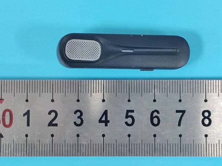
Click to zoom
Application Details
- Equipment Class
- DSS - Part 15 Spread Spectrum Transmitter
- Date of Grant
- Mar 02, 2022
- Application Purpose
- Original Equipment
- Date of Application
- Mar 02, 2022
- Equipment Note
- Wireless Microphone
- Frequency Range
- 2402.00000000 - 2480.00000000
- Country
- China
Documents & Files
Document Text
Text extracted from the exhibit documents filed with the FCC. Open a document above to read the original.
Users Manual
1 CATALOGUE GUIDE 1. ProductIntroduction ...................................................................................... 2 2. ProductSpecification ..................................................................................... 2 3. Packing List 4.How touse .......................................................................................3 .......................................................................................4 5.UI Functions ....................................................................................... 6 6.Trouble Shooting ....................................................................................... 8 7.How to Care ....................................................................................... 10 8.Product Warranty ....................................................................................... 11 WirelessKTVMicrophone UserManual 2 1. ProductIntroduction Thanks for purchasing wireless microphone, please read the following instructions carefully before use. • The product is a smart wireless microphone that provides professional- grade recording output. Plug and play, no app required. • The clip-on transmitter has a great sounding built-in mic and it is small and light enough to clip to shirts andclothing. • It can be used in different circumstances such as Live, Video Recording, Interviewing, online Teaching, KTV and others. 2. ProductSpecification SYSTEM SPECIFICATIONS Frequency range:2400~2483.5MHz Frequency Response :75Hz ~ 35kHz +/- 3dB Signal to noise ratio :-90dB Transmission delay :9mS The sampling rate :48KHz The bit depth :24bit Transfer longest distance: 49-65ft (barrier-free working distance) 32-49ft(obstacle distance or the noise is loud) Charging input voltage: DC 4.8~5.4V TRANSMITTER 3 Microphone type: built-in polymer battery Built-in battery capacity: 100mAh 3.7V Working Hour : 4 - 5 hours after fullycharged ChargingTime :About 1 hour (5V/1A) CHARGING CASE PowerCapacity :450mAh ChargingTime :1hour Note: After using the mic set, please put it in the storage and charging box in time to avoid the loss. 3. PackingList Number Product picture Text explanation 1 Charging box 2 Power button Charging port/ Monitor earphone port Microphone transmitter 3 TYPE-C charging cable 4 The TYPE-C charges the microphone at this Port 1..Press the powerkey 2..then blue light flashes PlugAnalog earphone to monitor at this Port + 4 TYPE-C audio conversion line or Lighting audio conversion line 4. How touse Step1: Preparation before the first use, Charge the charging box and transmitter for 1hours Small icon display on the phone 5 Note: As shown in the figure above, this product has the monitor function,ifthe does not need to monitor, it can plug in the charging cable to quickly charge the mobile phone at the same time This product has three selection of scene mode. Please select different scene mode according to the actual situation and your need. Operation In the connection state, short press the power buttonofthe transmitter The indicator flashes once in red and then turns blue —the Original mode .the sound quality of the recording is the best when used in a quiet environment The indicator flashes twice in red and then turns blue—the Noise reduction mode.It will reduce the noise when used in a noisy environment The indicator flashes three times in red and then turns blue—the KTV mode When you need to sing(The effect is better when the microphone is within 5cm from the mouth) 5. UIFunctions Microphone Transmitter Function Operation Light Poweron Long press the power button for 3s to turn o n Blue light flashes slowly Pairing Automatically search for pairing once starting up Blue light flashes During live broadcasting, charge the mobile phone quickly at the same time 6 Paired Auto pairing Red light on Poweroff Long press the power button for 3s or Automatic turn off after 1 min without connection / Three selection of scene mode Short press the switch when connected The flashes times of the Red light reprise different scene mode, then turn blue Clear the pa iring and Re set Turn on the Transmitter, then press the power button twice quickly, then Press power button for 3-5s immediately, don't release until the light turns from purple to blue. Blue light flashes slowly, then Blue turns purple; then purple turns blue Lowbattery alarm Battery is below 20% Red light on 7 Charging box FunctionFunction Operation Light Charging box with type-C Plug the TYPE-C Charging cable The blue light flashes, and the four running lights represent 25 / 50 / 75 / 100 power The charging box is fully charged / All four blue lights are on The charging box charges the microphone Put the microphoneinto the charging BOX the blue light in the charging BOX is always on, and the red light of the microphone is always on The microphone is fully charged / the blue light in the charging BOX is off, and the red light of the microphone is off. 8 6. TroubleShooting If the problem still cannot be solved, Please contact customer service NO. Common issues Possible Cause Solutions 1 The signal cuts in andout other devices are working at the same frequency If you have more than one microphones or some other devices, please make sure other sets are powered off to avoid interferences. Or try to pair again. 2 The lapel mic has to be very close to mouth in order to pick up myvoice KTV reverberation mode may be enabled Suggested to close to mouth and point the lapel mic to your mouth. 3 There is always harsh sound or loopback. Don’t be too close to the audio device. harshsound orloopback. 4 Can I use two sets together? Is there any interference with eachother? Yes. But please stagger the pairing time of the two sets of mic. Otherwise it will interfere with each other and need to reset and pair again 5 The Transmitter/ Charging box can’t charge May have triggered the battery protection mechanism. Need to activate battery. First, it must be charged for 10 minutes, then unplug and…
Text truncated - open the document above for the full version.
External Photos
Shenzhen Accurate Technology Co., Ltd. Project No.: SZNS1211118-59480E-RF Page 1 of 7 External Photos Shenzhen Accurate Technology Co., Ltd. Project No.: SZNS1211118-59480E-RF Page 2 of 7 Shenzhen Accurate Technology Co., Ltd. Project No.: SZNS1211118-59480E-RF Page 3 of 7 Shenzhen Accurate Technology Co., Ltd. Project No.: SZNS1211118-59480E-RF Page 4 of 7 Shenzhen Accurate Technology Co., Ltd. Project No.: SZNS1211118-59480E-RF Page 5 of 7 Shenzhen Accurate Technology Co., Ltd. Project No.: SZNS1211118-59480E-RF Page 6 of 7 Shenzhen Accurate Technology Co., Ltd. Project No.: SZNS1211118-59480E-RF Page 7 of 7
ID Label/Location Info
Label and location
Internal Photos
Shenzhen Accurate Technology Co., Ltd. Project No.: SZNS1211118-59480E-RF Page 1 of 2 Internal photos Antenna Shenzhen Accurate Technology Co., Ltd. Project No.: SZNS1211118-59480E-RF Page 2 of 2
Test Report
Note: This report may contain data that are not covered by the A2LA accreditation and are marked with an asterisk “ ★ ”. Shenzhen Accurate Technology Co., Ltd. is not responsible for the authenticity of any test data provided by the applicant. Data included from the applicant that may affect test results are marked with an asterisk ’*’. Customer model name, addresses, names, trademarks etc. are not considered data. This report cannot be reproduced except in full, without prior written approval of the Company. Unless otherwise stated the results shown in this test report refer only to the sample(s) tested. This report is valid only with a valid digital signature. The digital signature may be available only under the Adobe software above version 7.0. Shenzhen Accurate Technology Co., Ltd. 1/F., Building A, Changyuan New Material Port, Science & Industry Park, Nanshan District, Shenzhen, Guangdong, P.R. China Tel: +86 755-26503290 Fax: +86 755-26503396 Web: www.atc-lab.com Version 11: 2021-11-09 Page 1 of 69 FCC-BT TEST REPORT Applicant Name : Shen Zhen Dong Hua Xiang Technology Co., Ltd. Address : 4th Floor, Building B, Jinye Industrial Zone, 31 Queshan Road, Dalang Street, Longhua District, Shenzhen Report Number : SZNS1211118-59480E-RF FCC ID: 2A3PC-DX01 Test Standard (s) FCC PART 15.247 Sample Description Product Type: Wireless microphone Model No.: DX01 Multiple Model(s) No.: DX02, DX06, DX08, DX09, DX10, DX12, DX18, H6, H8, H1 Trade Mark: N/A Date Received: 2021-11-18 Date of Test: 2021-11-26 to 2021-11-29 Report Date: 2021-11-30 Test Result: Pass* * In the configuration tested, the EUT complied with the standards above. Prepared and Checked By: Approved By: Black Ding Candy Li EMC Engineer EMC Engineer Shenzhen Accurate Technology Co., Ltd. Report No.: SZNS1211118-59480E-RF Version 11: 2021-11-09 Page 2 of 69 FCC-BT TABLE OF CONTENTS GENERAL INFORMATION ....................................................................................................................................... 4 PRODUCT DESCRIPTION FOR EQUIPMENT UNDER TEST (EUT) ..................................................................................... 4 OBJECTIVE ................................................................................................................................................................... 4 TEST METHODOLOGY .................................................................................................................................................. 4 MEASUREMENT UNCERTAINTY .................................................................................................................................... 5 TEST FACILITY ............................................................................................................................................................. 5 SYSTEM TEST CONFIGURATION .......................................................................................................................... 6 DESCRIPTION OF TEST CONFIGURATION ...................................................................................................................... 6 EUT EXERCISE SOFTWARE .......................................................................................................................................... 6 SPECIAL ACCESSORIES ................................................................................................................................................. 6 EQUIPMENT MODIFICATIONS ....................................................................................................................................... 6 SUPPORT EQUIPMENT LIST AND DETAILS .................................................................................................................... 6 EXTERNAL I/O CABLE.................................................................................................................................................. 6 BLOCK DIAGRAM OF TEST SETUP ................................................................................................................................ 7 SUMMARY OF TEST RESULTS ............................................................................................................................. 10 TEST EQUIPMENT LIST ......................................................................................................................................... 11 FCC§15.247 (i), §1.1307 (b) (1) &§2.1093 – RF EXPOSURE .................................................................................. 12 APPLICABLE STANDARD ............................................................................................................................................ 12 TEST RESULT: ............................................................................................................................................................ 12 FCC §15.203 – ANTENNA REQUIREMENT .......................................................................................................... 13 APPLICABLE STANDARD ............................................................................................................................................ 13 ANTENNA CONNECTOR CONSTRUCTION .................................................................................................................... 13 FCC §15.207 (a) – AC LINE CONDUCTED EMISSIONS ..................................................................................... 14 APPLICABLE STANDARD ............................................................................................................................................ 14 EUT SETUP ................................................................................................................................................................ 14 EMI TEST RECEIVER SETUP ...................................................................................................................................…
Text truncated - open the document above for the full version.
Test Setup Photos
Shenzhen Accurate Technology Co., Ltd. Project No.: SZNS1211118-59480E-RF Page 1 of 4 Photo of Power Line Conducted Emission Measurement Test mode 1 Shenzhen Accurate Technology Co., Ltd. Project No.: SZNS1211118-59480E-RF Page 2 of 4 Test mode 2 Shenzhen Accurate Technology Co., Ltd. Project No.: SZNS1211118-59480E-RF Page 3 of 4 Photo of Radiated Emission Measurement Below 1GHz Test mode 1 Test mode 2 Shenzhen Accurate Technology Co., Ltd. Project No.: SZNS1211118-59480E-RF Page 4 of 4 Photo of Radiated Emission Measurement Above 1GHz
Contact Information
Applicant
Yuan Fang Cui
Test Firm
Shenzhen Accurate Technology Co., Ltd.Lisa Zhang
[email protected]+86-755-26503290
Technical Specifications
| # | Rule Parts | Frequency Range | Power Output |
|---|---|---|---|
| 1 | 15C | 2.40 GHz - 2.48 GHz | 4.00 mW |
Other Applications from Shen Zhen Dong Hua Xiang Technology Co.,Ltd.
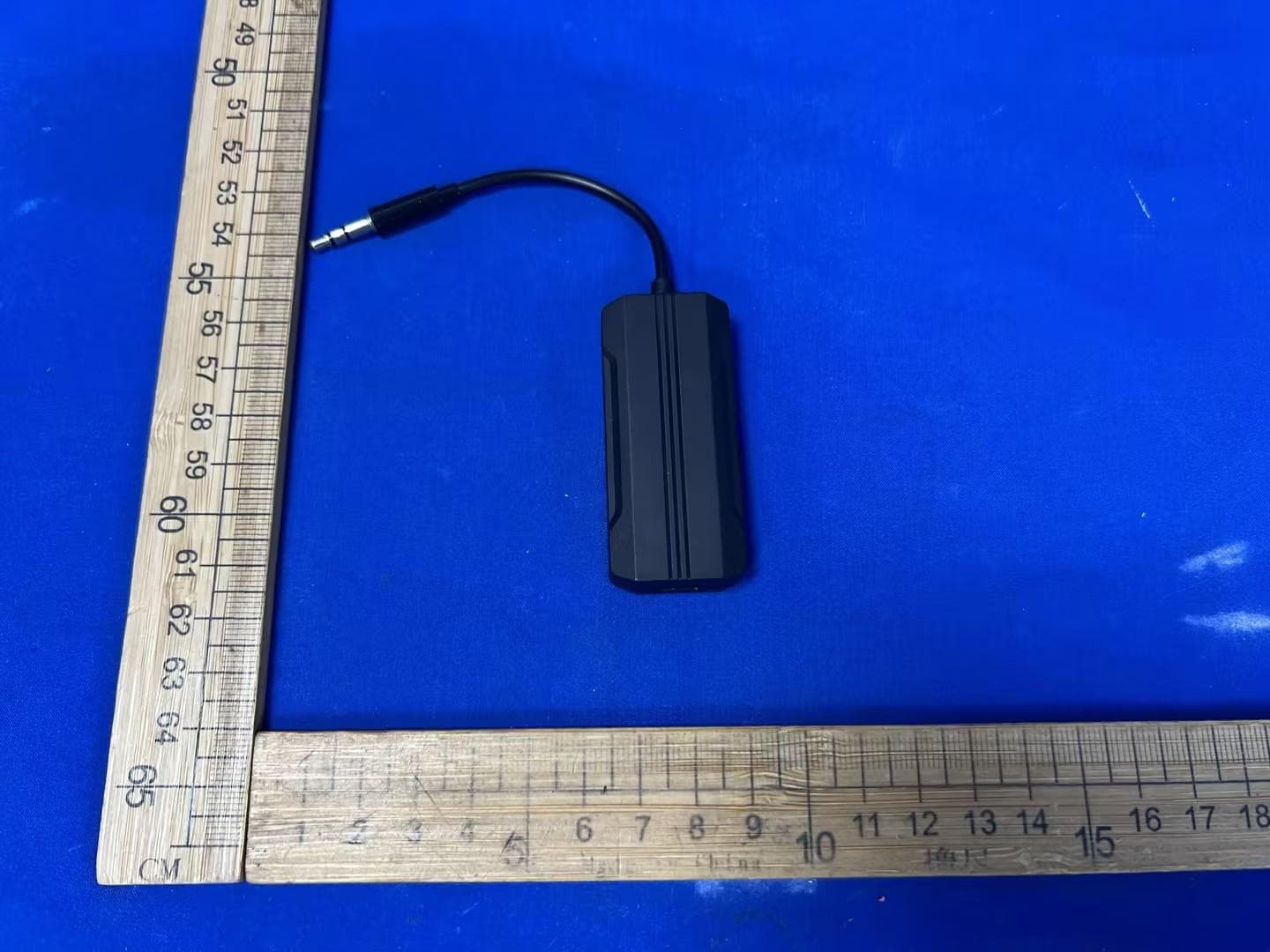
2A3PC-H2
Jun 24, 20262-IN-1 Bluetooth Audio Adapter
Equipment Class
DSS - Part 15 Spread Spectrum Transmitter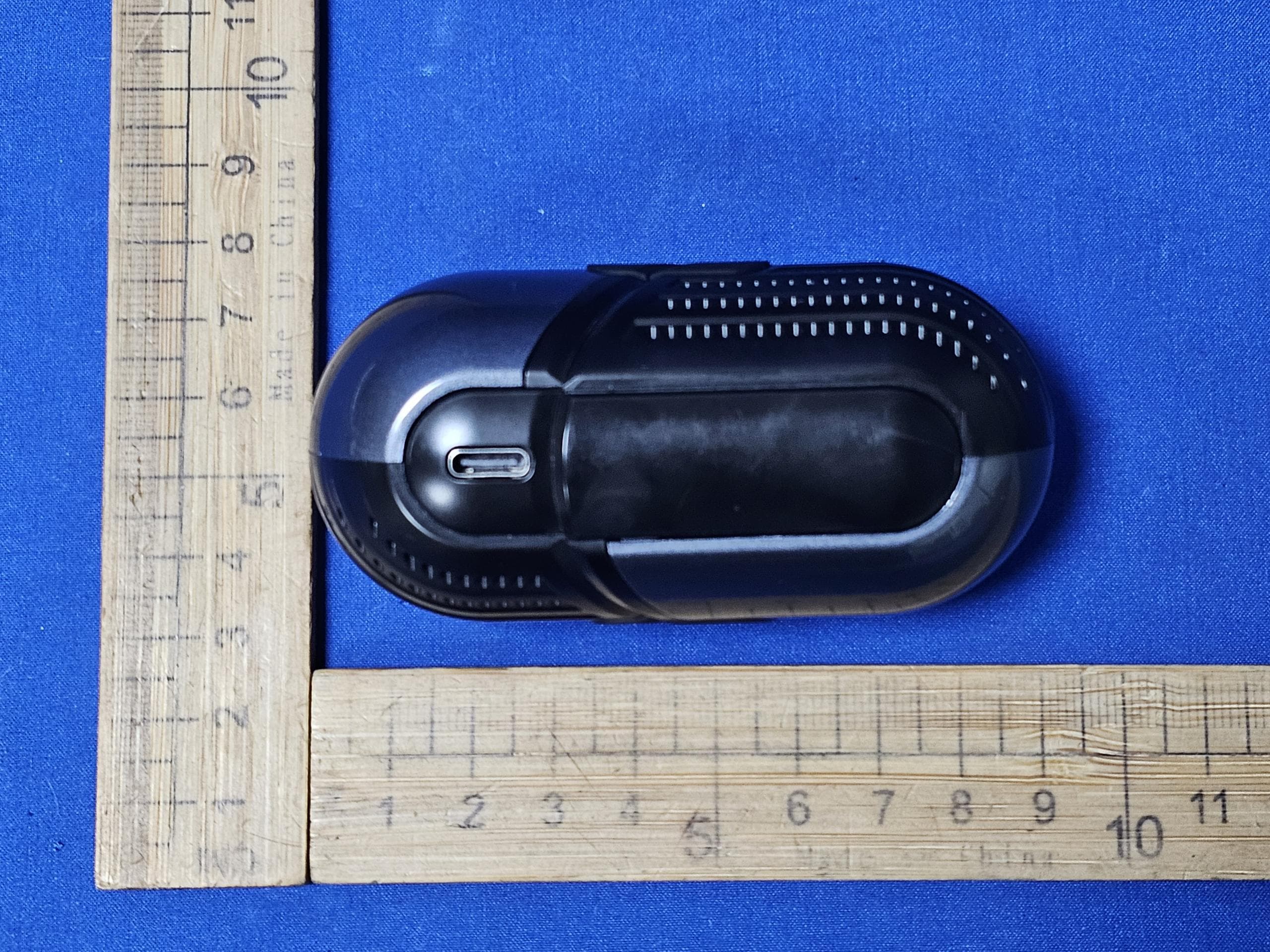
2A3PC-H5
Jun 08, 2026Wireless speaker
Equipment Class
DSS - Part 15 Spread Spectrum Transmitter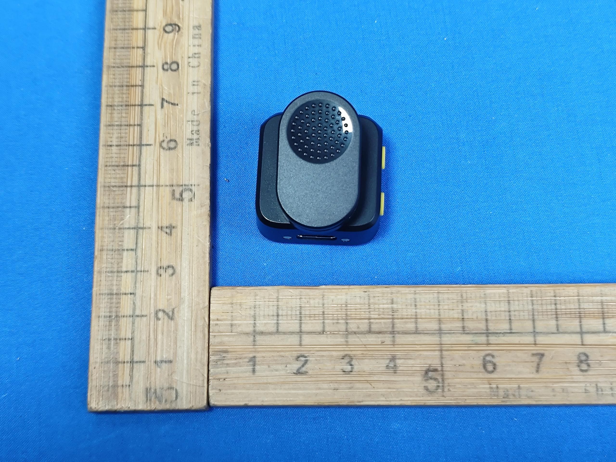
2A3PC-DX12
Mar 12, 2026Wireless Microphone
Equipment Class
DSS - Part 15 Spread Spectrum Transmitter