2A3PG-300215ZVIEW
Zgonic North America LLC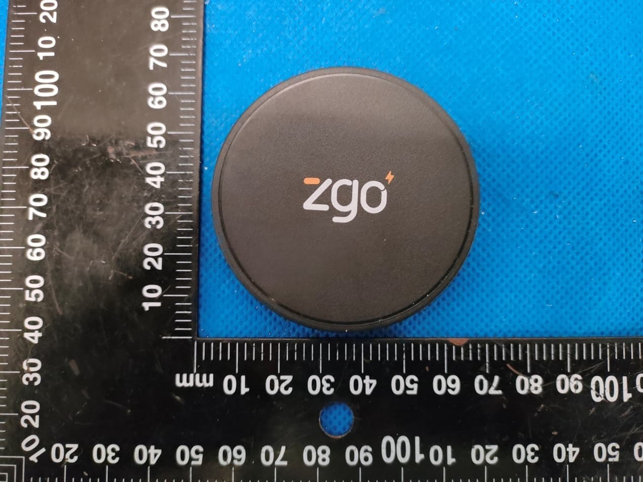
Click to zoom
Application Details
- Equipment Class
- 8CC - Part 18 Consumer Device
- Date of Grant
- Jul 04, 2022
- Application Purpose
- Original Equipment
- Date of Application
- Jul 04, 2022
- Equipment Note
- ZVIEW
- Frequency Range
- 0.11150000 - 0.20500000
- Company
- Zgonic North America LLC
- Country
- United States
Documents & Files
Document Text
Text extracted from the exhibit documents filed with the FCC. Open a document above to read the original.
Users Manual
WIRELESS CHARGER INSTRUCTION MANUAL SPECIFICATIONS SAFETY PRECAUTIONS FCC WARNING STATEMENT Wireless Charger Input: 5V 3A/9V 2.22A/12V/1.67A Charging Mode: 15W Dimensions: φ62 x 10.6mm Type-C Power Cable Type-c to Type-c - 1.8 meter PD + QC 3.0 Adapter Input: 100-240V,50/60Hz,0.8A Output: 5V 3A/9V 2.22A/12V/1.67A The two-part warning label described in FCC 15.19(a)(3), “This device complies with part 15 of the FCC Rules. Operation is subject to the following two conditions: (1) This device may not cause harmful interference, and (2) this device must accept any interference received, including interference that may cause undesired operation.” This equipment has been tested and found to comply with the limits for a Class B digital device, pursuant to Part 15 of the FCC Rules. These limits are designed to provide reasonable protection against harmful interference in a residential installation. This equipment generates, uses, and can radiate radio frequency energy and, if not installed and used in accordance with the instructions, may cause harmful interference to radio or television reception. However, there is no guarantee that interference will not occur in a particular installation. If this equipment does cause interference to radio and television reception, which can be determined by turning the equipment off and on, the user is encouraged to try to correct the interference by one or more of the following measures: - Reorient or relocate the receiving antenna. - Increase the separation between the equipment and receiver. - Connect the equipment into an outlet on a circuit different from that to which the receiver is connected. - Consult the dealer or an experienced radio/TV technician for help. This equipment complies with FCC radiation exposure limits set forth for an uncontrolled environment. This equipment should be installed and operated with minimum distance 20cm between the radiator and your body. This transmitter must not be colocated or operating in conjunction with any other antenna or transmitter. Changes or modifications not expressly approved by the party responsible for compliance could void the user’s authority to operate the equipment. - Use only certified power adapter as provided, non-certified power adapter may cause irregular or no charging. - Do not use products provided for anything other than its intended use. - Use product in location with temperature of 32°F(0°C) - 95°F (35°C), avoid heat source and direct sunlight. - Avoid water contact or any other liquid. If product becomes wet, unplug it from power source immediately. - Do not use product if dropped or damaged in any way. - Any repairs to products should be performed by a qualified electrician only. - Do not place magnetic cards or similar items near the product. - Use specified power source and voltage only. - Place charger on a flat and sturdy surface during use. - Keep product out of reach of children. Zview-50-0045 Rev 1.0 Slim Case (Within 4mm) Thickness more than 4mm Centrally Placed Crookedly Placed Magnetic PadNo metal objects on pad (Coins, keys, etc..) Metal Ring Case No metal foreign object between device and pad ISED Canada Statement:This device contains licence-exempt trasnsmitter(s)/receiver(s) thatcomply with Innovation, Science and Economic Development Canada 's licence-exempt RSS(s). Operation is subject to the following two conditions:1) this device may not cause interference and2) this device must accept any interference, including interference thatmay cause undesired operation of the device.Radiation Exposure: This equipment complies with Canada radiationexposure limits set forth for an uncontrolled environmentRF Exposure StatementTo maintain compliance with IC's RF Exposure guidelincs, This cquipment should be.installed and operated with minimum distance of 10cm the radiator your body. This device and its antenna(s) must not be co-located or operation in conjunction with any other antenna or transmitter Déclaration de l'ISED Canada :Cet appareil contient des émetteurs / récepteurs exempts de licencese conformer à l'innovation, la science et le développement économiqueLes RSS du Canada exemptes de licence. Leur fonctionnementsuivant deux conditions:1) cet appareil ne peut pas causer d'interférences et2) ce dispositif doit accepter toute interférence, y comprispeut provoquer le fonctionnement indésirable de l'appareil.Exposition aux rayonnements : Cet équipement est conforme aux radiations du Canadalimites d'exposition pour un environnement incontr ô lé noncé d'exposition RF Pour maintenir le respect des guides d'exposition RF d'IC,cquipment doit être.installé et actionné avec une distance minimale de 10cm le radiateur de votre corps. Cet appareil et ses antennes ne doivent pas être co- localisé ou en opération en conjonction avec toute autre antenne ou émetteur
Cover Letter(s)
Office o Federa 7435 O Columb USA Subjec t FCC ID To Wh o Pursua are req u docume These d propriet might b It is ou r corresp docume authoriz Sincer e Signat u Name: Title: E n of Engineeri l Communic Oakland Mills bia, MD 210 t; Request f D: 2A3PG-30 om It May C nt to the pro uesting the ents from pu documents tary informa be harmful to Schema Block D Parts Lis Operatio r understand pondence du ents and thi zation is iss ely, ure: Jacob Glic k ngineering ing Techno cations Com s Road 046 for Confiden 00215 Concern, ovisions of t Commissio ublic disclos contain det ation in ope o our comp atic Diagram iagram st onal Descri ding that all uring the ce s informatio sued. kstein Manage r Zgonic logy mmission ntiality the Commis on to withho sure indefin tailed syste ration of th e any and wo m ption l measurem ertification re on will be av c North Am ssion’s rule old the follow nitely. m and equi e equipmen ould give co ment test rep eview proce vailable for merica LLC s Title 47 S wing attach pment desc nt. The publ ompetitors a ports, FCC ess cannot public revi e Sections §0. hment(s) as criptions an ic disclosu r an unfair ad ID label for be granted ew once the Date: Jun. 457 and §0 confidentia d are consi re of these d vantage in mat and as confide n e grant of eq 17, 2022 0.459, we al dered as documents the market . ntial quipment .
External Photos
Annex A External Photos Test Model No.: 30-0215 Page 1 of 4 Test Model No.: 30-0215 Page 2 of 4 Test Model No.: 30-0215 Page 3 of 4 Test Model No.: 30-0215 Page 4 of 4
ID Label/Location Info
FCC ID LABEL: Ca. 5mm x 10mm Label Location FCC ID: 2A3PG-300215
Internal Photos
Annex B Internal Photo Test Model No.: 30-0215 Page 1 of 2 Antenna Antenna Test Model No.: 30-0215 Page 2 of 2
RF Exposure Info
Page 1 of 10 Report No.: HK2205302353-2E FCC TEST REPORT Test report On Behalf of Zgonic North America LLC For ZVIEW Model No.: 30-0215 FCC ID: 2A3PG-300215 Prepared For : Zgonic North America LLC 6665 Corners Industrial Court, Suite D Norcross, Georgia 30092 Prepared By : Shenzhen HUAK Testing Technology Co., Ltd. 1-2/F., Building B2, Junfeng Zhongcheng Zhizao Innovation Park, Heping, Fuhai Street, Bao’an District, Shenzhen, Guangdong, China Date of Test: May. 30, 2022 ~ Jun. 10, 2022 Date of Report: Jun. 10, 2022 Report Number: HK2205302353-2E Page 2 of 10 Report No.: HK2205302353-2E Note: 1. For a more detailed features description, please refer to the manufacturer’s specifications or the User's Manual. 2. Channel List Channel Frequency (KHz) Channel Frequency (MHz) Channel Frequency (MHz) Channel Frequency (MHz) 01 122 The EUT antenna is Coil Antenna. No antenna other than that furnished by the responsible party shall be used with the device. 2. SUMMARY OF TEST RESULTS 2.1. Test procedures according to the technical standards: FCC KDB680106 D01 RF Exposure Wireless Charging Apps v03r01 FCC CFR 47 Standard Section Test Item Judgment Remark FCC CFR 47 part1, 1.1310 KDB680106 D01v03r01 (3)(3) Electric Field Strength (E) (V/m) PASS Magnetic Field Strength (H) (A/m) PASS 2.2. Measurement Uncertainty The reported uncertainty of measurement y ±U, where expended uncertainty U is based on a standard uncertainty multiplied by a coverage factor of k=2, providing a level of confidence of approximately 95 %. No. Item Uncertainty 1 All emissions, radiated(<30M)(9KHz-30MHz) ±3.90dB 2 Temperature ±0.5°C 3 Humidity ±2% Page 3 of 10 Report No.: HK2205302353-2E 2.3. Test Mode EUT Mode Description Charging Cell phone setting 15W 2.4. Test Instruments Description Brand Model No. Frequency Range Calibrated Date Calibrated Until Exposure Level Te s t e r narda ELT-400 N-0231 Feb. 18, 2022 Feb. 17, 2023 Magnetic field probe 100cm 2 narda ELT probe 100cm2 M0675 Feb. 18, 2022 Feb. 17, 2023 NOTE: 1. The calibration interval of the above test instruments is 12 months. Page 4 of 10 Report No.: HK2205302353-2E 3. MAXIMUM PERMISSIBLE EXPOSURE Limit of Maximum Permissible Exposure Limits for Occupational / Controlled Exposure Frequency Range (MHz) Electric Field Strength (E) (V/m) Magnetic Field Strength (H) (A/m) Power Density (S) (mW/ cm²) Averaging Time |E|²,|H|² or S (minutes) 0.3-3.0 614 1.63 (100)* 6 3.0-30 1842 / f 4.89 / f (900 / f)* 6 30-300 61.4 0.163 1.0 6 300-1500 F/300 6 1500-100,000 5 6 Limits for General Population / Uncontrolled Exposure Frequency Range (MHz) Electric Field Strength (E) (V/m) Magnetic Field Strength (H) (A/m) Power Density (S) (mW/ cm²) Averaging Time |E|²,|H|² or S (minutes) 0.3-1.34 614 1.63 (100)* 30 1.34-30 824/f 2.19/f (180 / f)* 30 30-300 27.5 0.073 0.2 30 300-1500 F/1500 30 1500-100,000 1 30 Note 1: f = frequency in MHz ; *Plane-wave equivalent power density. Note 2: For the applicable limit, see FCC 1.1310, 680106 D01 RF Exposure Wireless Charging Apps v03r01. Note 3: Emissions between 100 kHz to 300 kHz should be assessed versus the limits at 300 kHz in Table 1 of Section 1.1310: 614 V/m and 1.63A/m. A KDB inquiry is required to determine the applicable exposure limits below 100 kHz. Page 5 of 10 Report No.: HK2205302353-2E 4. TEST PROCEDURE a. For devices designed for typical desktop applications, such a wireless charging pads, RF exposure evaluation should be conducted assuming a user separation distance of (H-field & E- field strengths for all sides is 15cm, H-field strengths of top side is 20cm). E and H field strength measurements or numerical modeling may be used to demonstrate compliance. Measurements should be made from all sides and the top of the primary/client pair, with the 15 cm measured from the center of the probe(s) to the edge of the device. 4.1 Test Setup 4.2 Result Of Maximum Permissible Exposure Page 6 of 10 Report No.: HK2205302353-2E All test modes are tested, and the report shows only the worst mode: 15W. For Full load mode: H-Field Strength at 15 cm (E top side: 20cm) from the edges surrounding the EUT (A/m) Field strength Test Position A Test Position B Test Position C Test Position D Test Position E Limits (A/m) uT 0.458 0.341 0.526 0.469 0.531 / A/m 0.366 0.273 0.421 0.375 0.425 1.63 Note. Calculation: A/m=uT/1.25 For Half Load mode: H-Field Strength at 15 cm (E top side: 20cm) from the edges surrounding the EUT (A/m) Field strength Test Position A Test Position B Test Position C Test Position D Test Position E Limits (A/m) uT 0.425 0.351 0.619 0.341 0.422 / A/m 0.340 0.281 0.495 0.273 0.338 1.63 Note. Calculation: A/m=uT/1.25 For No load mode: H-Field Strength at 15 cm (E top side: 20cm) from the edges surrounding the EUT (A/m) Field strength Test Position A Test Position B Test Position C Test Position D Test Position E Limits (A/m) uT 0.481 0.338 0.360 0.427 0.541 / A/m 0.385 0.270 0.288 0.342 0.433 1.63 Note. Calculation: A/m=uT/1.25 Page 7 of 10 Report No.: HK2205302353-2E Remark: According KDB 680106 D01 RF Exposure Wireless Charging App v03r01, section 5, b). The aggregate H-field strengths at 15 cm surrounding the device and 20 cm above the top surface from all simultaneous transmitting coils are demonstrated to be less than 50% of the MPE limit. The E- field evaluation conducted assuming a user separation distance of 15 cm according to the KDB 680106 D01 RF Exposure Wireless Charging App v03r01 section 3, c). Result: The device comply with the RF exposure requirement according to 680106 D01 v03r01, section 5, b): (1) Power transfer frequency is less than 1 MHz. -The device operate in the frequency range for 111.5KHz~205KHz (2) Output power from each primary coil is less than or equal to 15 watts. - The maximum output power of cell phone is 15W (3) The system may consist of more than one source primary coils, charging one or more clients. If more than one primary coil is present, the coil pairs can be powered on at the same time - The tran…
Text truncated - open the document above for the full version.
Test Report
Page 1 of 21 Report No.: HK2205302353-1E FCC TEST REPORT Test report On Behalf of Zgonic North America LLC For ZVIEW Model No.: 30-0215 FCC ID: 2A3PG-300215 Prepared For : Zgonic North America LLC 6665 Corners Industrial Court, Suite D Norcross, Georgia 30092 Prepared By : Shenzhen HUAK Testing Technology Co., Ltd. 1-2/F., Building B2, Junfeng Zhongcheng Zhizao Innovation Park, Heping, Fuhai Street, Bao’an District, Shenzhen, Guangdong, China Date of Test: May. 30, 2022 ~ Jun. 10, 2022 Date of Report: Jun. 10, 2022 Report Number: HK2205302353-1E Page 2 of 21 Report No.: HK2205302353-1E TEST RESULT CERTIFICATION Applicant’s name ................. : Zgonic North America LLC Address.................................. : 6665 Corners Industrial Court, Suite D Norcross, Georgia 30092 Manufacture's Name ............ : Oxti Pte Ltd Address.................................. : 22 Boon Lay Way #01-62 Tradehub21 S609968 Product description Trade Mark: N/A Product name ............................ : ZVIEW Model and/or type reference : 30-0215 Standards ............................. : FCC CFR 47 PART 18 This publication may be reproduced in whole or in part for non-commercial purposes as long as the Shenzhen HUAK Testing Technology Co., Ltd. is acknowledged as copyright owner and source of the material. Shenzhen HUAK Testing Technology Co., Ltd. takes no responsibility for and will not assume liability for damages resulting from the reader's interpretation of the reproduced material due to its placement and context. Date of Test ............................................ : Date (s) of performance of tests ............. : May. 30, 2022 ~ Jun. 10, 2022 Date of Issue ........................................... : Jun. 10, 2022 Test Result ............................................... : Pass Testing Engineer : (Gary Qian) Technical Manager : (Eden Hu) Authorized Signatory : (Jason Zhou) Page 3 of 21 Report No.: HK2205302353-1E Table of Contents Page 1 . TEST SUMMARY 5 1.1 . Test Procedures And Results 5 1.2 . Information of the Test Laboratory 5 1.3 . Measurement Uncertainty 5 2. GENERAL INFORMATION 6 2.1. General Description of EUT 6 2.2. Carrier Frequency of Channels 7 2.3. Operation of EUT during testing 7 2.4. Test Mode 7 2.5. Description of Test Setup 8 2.6. Measurement Instruments List 9 3. CONDUCTED EMISSION TEST 10 3.1. Block Diagram of Test Setup 10 3.2. Conducted Power Line Emission Limit 10 3.3. Test Procedure 10 4. RADIATED EMISSIONS 13 4.1. Block Diagram of Test Setup 13 4.2. Rules and specifications 13 4.3. Test Procedure 14 4.4. Test Result 14 5. ANTENNA REQUIREMENT 18 6. PHOTOGRAPH OF TEST 19 7. PHOTOS OF THE EUT 21 Page 4 of 21 Report No.: HK2205302353-1E ** Modified History ** Revision Description Issued Data Remark Revision 1.0 Initial Test Report Release Jun. 10, 2022 Jason Zhou Page 5 of 21 Report No.: HK2205302353-1E 1. TEST SUMMARY 1.1. Test Procedures And Results DESCRIPTION OF TEST SECTION NUMBERRESULT CONDUCTED EMISSIONS TEST 18.307 COMPLIANT RADIATED EMISSION TEST 18.305 COMPLIANT Note: 1. PASS: Test item meets the requirement. 2. Fail: Test item does not meet the requirement. 3. N/A: Test case does not apply to the test object. 4. The test result judgment is decided by the limit of test standard. 1.2. Information of the Test Laboratory Shenzhen HUAK Testing Technology Co., Ltd. Add.: 1-2/F., Building B2, Junfeng Zhongcheng Zhizao Innovation Park, Heping, Fuhai Street, Bao’an District, Shenzhen, Guangdong, China Testing Laboratory Authorization: A2LA Accreditation Code is 4781.01. FCC Designation Number is CN1229. Canada IC CAB identifier is CN0045. CNAS Registration Number is L9589. 1.3. Measurement Uncertainty Measurement Uncertainty Conducted Emission Expanded Uncertainty =2.71dB, k=2 Radiated emission expanded uncertainty(9kHz-30MHz) = 3.90dB, k=2 Radiated emission expanded uncertainty(30MHz-1000MHz)= 3.90dB, k=2 Radiated emission expanded uncertainty(Above 1GHz) = 4.28dB, k=2 Page 6 of 21 Report No.: HK2205302353-1E 2. GENERAL INFORMATION 2.1. General Description of EUT Equipment: ZVIEW Model Name: 30-0215 Series Models: N/A Model Difference: N/A Trade Mark: N/A FCC ID: 2A3PG-300215 Antenna Type: Coil Antenna Antenna Gain: 0dBi Operation frequency: 111.5KHz~205KHz Test frequency: 122KHz Number of Channels: 1 Modulation Type: ASK Power Source: Input: 5V, 3A/9V, 2.22A/12V, 1.67A Wireless Output:15W Power Rating: Input: 5V, 3A/9V, 2.22A/12V, 1.67A Wireless Output:15W Page 7 of 21 Report No.: HK2205302353-1E 2.2. Carrier Frequency of Channels Operation Frequency each of channel Channel Frequency 1 122KHz 2.3. Operation of EUT during testing Operating Mode The mode is used: Transmitting mode 2.4. Test Mode EUT Mode Description Charging Cell phone setting 15W Page 8 of 21 Report No.: HK2205302353-1E 2.5. Description of Test Setup Operation of EUT during conducted testing: AC Plug Operation of EUT during radiation testing: AC Plug Adapter information Model: MK-P202USC Input: 100-240V, 50-60Hz, 0.5A Output:5V, 3A/9V, 2.22A/12V, 1.67A Mobile phone information Model: Iphone XR The sample was placed (0.8m (30MHz~1GHz), 0.8m (9KHz~30MHz) ) above the ground plane of 3m chamber. Measurements in both horizontal and vertical polarities were performed. During the test, each emission was maximized by: having the EUT continuously working, investigated all operating modes, rotated about all 3 axis (X, Y & Z) and considered typical configuration to obtain worst position, manipulating interconnecting cables, rotating the turntable, varying antenna height from 1m to 4m in both horizontal and vertical polarizations. The emissions worst-case are shown in Test Results of the following pages. The worst case is X position. Adapter EUT load Adapter EUT Mobile phone Page 9 of 21 Report No.: HK2205302353-1E 2.6. Measurement Instruments List Item Equipment Manufacturer Model No.Serial No. Last Cal. Cal. Interval 1. L.I.S.N. Artificial Mains Network R&S ENV216 HKE-002 Feb. 18, 20221 Year 2. Receiver R&S …
Text truncated - open the document above for the full version.
Test Setup Photos
Radiated Emissions Conducted Emissions
Contact Information
Applicant
Jacob Glickstein(Engineering Manager)
Technical Contact
Test Firm
Shenzhen HUAK Testing Technology Co., Ltd.Jason Zhou
[email protected]86-755-23029901
Technical Specifications
| # | Rule Parts | Frequency Range | Power Output |
|---|---|---|---|
| 1 | 18 | 0.1115 MHz - 0.205 MHz | - |