2A3Q9-UWTCHV3UGen Watch
Xperience Robotics Inc. d/b/a UGen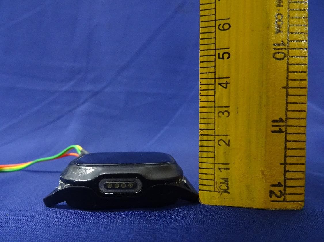
Click to zoom
Application Details
- Equipment Class
- DXX - Part 15 Low Power Communication Device Transmitter
- Date of Grant
- Dec 18, 2022
- Application Purpose
- Original Equipment
- Date of Application
- Dec 08, 2022
- Equipment Note
- UGen Watch
- Frequency Range
- 2402.00000000 - 2480.00000000
- Country
- United States
Documents & Files
Document Text
Text extracted from the exhibit documents filed with the FCC. Open a document above to read the original.
Users Manual
www.ugen.health 10:25 PM Stop Exersice? YESNO When done, double tap to stop exercise? Tap ‘Yes’ to stop Start Exercise Double tap on any exercise to start Tap ‘Yes” to start Green dot means you can now start doing your exercise. 10:25 PM Start Exersice? YESNO 10:25 PM Blue light pointing down and f ront facing Exercises • St. Hip Flexion • St. Hip Extension • Squat • Mini Squat Device at Thigh 3 Instruction for users Turn the watch & the sensor ON before wearing them. It will help with wearing them correctly. 1 Blue light pointing down and f ront facing Exercises • Long arc quad • SLR Flexion • Heel Slide Device at Knee 2 Soulder Exercises Blue light pointing down and f ront facing How to Wear the Sensor Place your arms to your side & stand upright & still until you feel the Vibration & hear a sound (take 5-7 second) It will now take you to your exercise automatically 10:25 PM Calibration in Process 10:25 PM Calibration Successfull Do Calibration Double Tap Tap Yes If sensor already turned ‘ON’ Do Calibration 10:25 PM 10:25 PM Start Calibration? YESNO 10:25 PM Connect Partner Go Back Compliance Statement This device complies with part 15 of the FCC Rules. Operation is subject to the following two conditions: (1) This device may not cause harmful interference, and (2) This device must accept any interference received, including interference that may cause undesired operation Cet appareil est conforme à la partie 15 des règles de la FCC. Le fonctionnement est soumis aux deux conditions suivantes : (1) Cet appareil ne doit pas causer d’interférences nuisibles, et (2) Cet appareil doit accepter toute interférence reçue, y compris les interférences pouvant provoquer un fonctionnement indésirable. Disclaimer This product is an electronic monitoring product and is not intended as a medical reference. We reserve the right to modify or to improve any of the functions described in this manual without any prior notice. At the same time, we hold the right to continuously update the product content. Caution Statements Information to the User • Any changes or modifications not expressly approved by the party responsible for compliance could void the user’s authority to operate this equipment. • Do not puncture or harm the exterior surface of the product in any way. This equipment has been tested and found to comply with the limits for a Class B digital device, pursuant to part 15 of the FCC Rules. These limits are designed to provide reasonable protection against harmful interference in a residential installation. This equipment generates, uses and can radiate radio f requency energy and, if not installed and used in accordance with the instructions, may cause harmful interference to radio communications. However, there is no guarantee that interference will not occur in a particular installation. If this equipment does cause harmful interference to radio or television reception, which can be determined by turning the equipment off and on, the user is encouraged to try to correct the interfer- ence by one or more of the following measures: • Reorient or relocate the receiving antenna. • Increase the separation between the equipment and receiver. • Connect the equipment into an outlet on a circuit different f rom that to which the receiver is connected. • Consult the dealer or an experienced radio/TV technician for help. You & I Work Together Bluetooth Real Time Feedback Movement Tracking Touchscreen Water & Dust Resistant www.ugen.health Technical Description The main purpose of the document to provide design information for the Hardware of UGen wearable device. The UGen wearable device will be used for monitor and tracking the body movements for prescribed exercise. The UGen wearable device has an IMU, which will detect motion of device along with movements. This movements will be checked using the software algorithm. Movements of devices is measured and compared using algorithm and if it’s not correct it will give user an indication using Vibrations/ buzzer. Device will be used to store some specified movement used in Exercise. Device will send information to BLE server for tracking/monitoring the data. Watch The Watch device contains LCD Touch display in it. By using Watch device only, we can start the exercise or calibration with Sensor. To start the Watch device, first we must press and hold the user button until the user does not feel the vibration of the device. The device has vibration motor in its architecture for better prospect of application. The device will start, and it has been indicated by one beep sound and display will indicate the welcome message and its particular MAC ID on which the device will work. To do the Hard reset of the device, user need to press and hold the user button for 14 to 15 seconds. www.ugen.health Back view master Back view slave FCC: 2A3Q9-USNSRV3 FCC: 2A3Q9-UWTCHV3
Cover Letter(s)
Address: 291 Independence Blvd, Suite 522, Virginia beach, Virginia-23462 Contact: +17572549888 Email: [email protected] TUV Rheinland of North America, Inc. 1279 Quarry Lane., Suite. A Pleasanton, CA 94566 To Whom It May Concern: I appoint Mr. Raghavendra Kulkarni of TUV Rheinland India Ltd. 27/B, 2nd cross, Electronic City, Phase 1 Bangalore – 560 100. INDIA to act as our agent in the preparation of this application for equipment certifi- cation. I certify that submitted documents properly describe the device or system for which equipment certification is sought. I also certify that each unit manufactured, imported or marketed, as defined in the FCC or Industry Canada’s regulations will have affixed to it a label identical to that submitted for approval with this application. For instances where our authorized agent signs the application for certification on our behalf, I acknowl- edge that all responsibility for complying with the terms and conditions for Certification, as specified by TUV Rheinland Group, still resides with Mahesh K, Honeywell International Inc, 512 Virginia Dr Fort Washington, Pennsylvania United States 19034. For TCB applications, We certify that we are not subject to denial of federal benefits, that includes FCC benefits, pursuant to Section 5301 of the Anti-Drug Abuse Act of 1988, 21 U.S.C. 862. Further, no party, as defined in 47 CFR 1.2002 (b), to the application is subject to denial of federal benefits, that includes FCC benefits. Thank you, Agency Agreement Date: ___________________ Agreement is valid for 12 months from the above date. By: __________________________ __________________________ (Signature) (Print name) ___________________________ __________________________ (Title) (Telephone) On behalf of: __________________________ (Company Name) Authority to Act as Agent Date: ______________ Xperience Robotics Inc. d/b/a Ankit Shah CEO +17572549888 UGen October 20, 2022 October 20, 2022
Cover Letter(s)
1. UGen Watch ETU Photo 2.4G Antenna Figure 1 Antenna Figure 2 2. 2.4GHz Antenna(BT840L) Antenna Gain 2400 2450 2500 Unit -4.96 -3.89 -3.52 dBi 3. Polar Diagram(BT840L) 1) 2.4GHz Antenna 2) 2.45GHz Antenna 3) 2.45GHz Antenna
External Photos
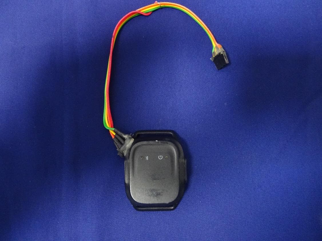
Produkte Products www.tuv.com EUT External Photos Reference Test Report No: ULR-TC568822300000002F Seite 1 von 4 Page 1 of 4 EUT External Photos Figure 1: Front view of the EUT Figure 2: Rear view of the EUT Produkte Products www.tuv.com EUT External Photos Reference Test Report No: ULR-TC568822300000002F Seite 2 von 4 Page 2 of 4 Figure 3: Side view of the EUT Figure 4: Side view of the EUT Produkte Products www.tuv.com EUT External Photos Reference Test Report No: ULR-TC568822300000002F Seite 3 von 4 Page 3 of 4 Figure 5: Dimensional view of the EUT Figure 6: Dimensional view of the EUT Produkte Products www.tuv.com EUT External Photos Reference Test Report No: ULR-TC568822300000002F Seite 4 von 4 Page 4 of 4 Figur 7: Dimension view of the EUT ****End of EUT External Photos****
ID Label/Location Info
Sticker Material :- White Polyester TC/S333/50#SCK D E F C 1234 B A 3215 C D 4678 A B PATENT NO: APPROVED BY CHECKED BY DATE DRAWN BY NAME "Hi_Move_Main Assembly A3 SHEET 1 OF 1 THE INFORMATION CONTAINED IN THIS DRAWING IS THE SOLE PROPERTY OF inventINDIA INNOVATIONS PVT. LTD. ANY REPRODUCTION IN PART OR AS A WHOLE WITHOUT THE WRITTEN PERMISSION OF inventINDIA INNOVATIONS PVT. LTD. IS PROHIBITED. Sticker PROJECT NO: MATERIAL: FINISH: PROJECT NAME: TITLE: SIZE: 0 REV:DRAWING NO.: SURFACE ROUGHNESS: DO NOT SCALE THE DRAWING PROJECTION: UNLESS OTHERWISE SPECIFIED DIMENSIONS ARE IN MM• REMOVE ALL SHARP EDGES • AND BURRS APPLIED PRACTICES UNLESS AND OTHERWISE SPECIFIED TOLERANCES: REFER TOLERANCE TABLE WEIGHT: inventINDIA PROPRIETARY & CONFIDENTIAL FCC: 2A3Q9-UWTCHV3 FCC: 2A3Q9-UWTCHV3 16 x6 mm Side view master Back view master Front view master Side view slave Back view slave Front view slave 16 x6 mm FCC: 2A3Q9-USNSRV3 FCC: 2A3Q9-USNSRV3
Internal Photos
Produkte Products www.tuv.com EUT Internal Photos Reference Test Report No: ULR-TC568822300000002F Seite 1 von 2 Page 1 of 2 EUT Internal Photos Figure 1: EUT Front panel removed Figure 2: Front view of the PCB Produkte Products www.tuv.com EUT Internal Photos Reference Test Report No: ULR-TC568822300000002F Seite 2 von 2 Page 2 of 2 Figure 3: Rear view of PCB ****End of EUT Internal Photos****
RF Exposure Info
Produkte Products www.tuv.com RF Exposure Reference Test Report No: ULR-TC568822300000002F Seite 1 von 2 Page 1 of 2 RF Exposure Report Following FCC KDB 447498 D01 General SAR test exclusion guidelines The corresponding SAR exclusion threshold condition, listed below: 1) The 1-g and 10-g SAR test exclusion thresholds for 100 MHz to 6 GHz at test separation Distances ≤ 50 mm are determined by: [(max. power of channel, including tune-up tolerance, mW)/ (min. test separation distance, mm)] · [√f (GHz)] ≤ 3.0 for 1-g SAR and ≤ 7.5 for 10-g. Extremity SAR, where f(GHz) is the RF channel transmit frequency in GHz Power and distance are rounded to the nearest mW and mm before calculation. The result is rounded to one decimal place for comparison The test exclusions are applicable only when the minimum test separation distance is ≤ 50 mm and for transmission frequencies between 100 MHz and 6 GHz. When the minimum test separation distance is < 5 mm, a distance of 5 mm according to 5) in section 4.1 is applied to determine SAR test exclusion(447498 D01 General RF Exposure Guidance v06) 2) At 100 MHz to 6 GHz and for test separation distances > 50 mm, the SAR test exclusion threshold Is determined according to the following [Power allowed at numeric threshold for 50 mm in step 1) + (test separation distance - 50 mm)·( f(MHz)/150)] mW, at 100 MHz to 1500 MHz [Power allowed at numeric threshold for 50 mm in step 1) + (test separation distance - 50 mm)·10] mW at > 1500 MHz and ≤ 6 GHz 3) At frequencies below 100 MHz, the following may be considered for SAR test exclusion, The power threshold at the corresponding test separation distance at 100 MHz in step 2) is multiplied by [1 + log(100/f(MHz))] for test separation distances > 50 mm and < 200 mm The power threshold determined by the equation in a) for 50 mm and 100 MHz is multiplied by ½ for test separation distances ≤ 50 mm SAR measurement procedures are not established below 100 MHz When SAR test exclusion cannot be applied, a KDB inquiry is required to determine SAR evaluation requirements for any test results to be acceptable. Produkte Products www.tuv.com RF Exposure Reference Test Report No: ULR-TC568822300000002F Seite 2 von 2 Page 2 of 2 SAR Test Exclusion Thresholds Exclusion calculation considering transmitting power level Frequency (GHz) Max.Power (dBm) Tune- up value Max.Power e.i.r.p Including Tune-up Tolarence (dBm) Max.Power Including Tune-up Tolarence (mW) Minimum test separation distance (mm) SAR Test Exclusion Calculation Values 1-g Extremity SAR Test exclusion Threshold 2.480 4 1 5 3.16 2.48 2.008048322 3 From above table calculation the EUT is exempted from routine SAR evaluation Exclusion calculation considering radiated E I R P Frequen cy (GHz) Max.Power (dBm) Tune- up value Antenn a gain (dBi) Max.Power Including Tune-up Tolarence & antenna gain (dBm) Max.Power Including Tune-up Tolarence & antenna gain (mW) Minimu m test separati on distance (mm) SAR Test Exclusion Calculation Values 1-g Extremity SAR Test exclusion Threshold 2.480 4 1 -3.52 1.48 1.40 2.48 0.892841071 3 From above table calculation the EUT is exempted from routine SAR evaluation Note: 1. SAR exclusion threshold is calculated using condition1 formulas. 2. Transmitting power level is taken from the RF test report ULR-TC568822300000002F 3. Antenna gian values are taken from Antenna data sheet. ****END OF TEST REPORT*****
Test Report
Prüfbericht – Produkte Test Report - Products Prüfbericht-Nr.: Test report no.: IN22JC5S 001 ULR-TC568822300000002F Auftrags-Nr.: Order no.: 166582984 001 Seite 1 von 54 Page 1 of 54 Kunden-Referenz-Nr.: Client reference no.: NA Auftragsdatum: Order date: 2021-08-30 Auftraggeber: Client: UGen 291, Independence Blvd, Suite 522 Virginia Beach, VA 23462, USA Prüfgegenstand: Test item: UGen Watch Bezeichnung / Serien-Nr.: Identification / serial no.: Engineering sample Auftrags-Inhalt: Order content: Testing and issue of Test Report and Grant Certificate Prüfgrundlage: Test specification: FCC Part 15 Subpart C 15.205, 15.207, 15.209, 15.215 & 15.249 Wareneingangsdatum: Date of sample receipt: 2021-09-09 Prüfmuster-Nr .: Test sample no .: A003126335-003 Prüfzeitraum: Testing period: 2021-09-23 - 2021-09-29 Ort der Prüfung: Place of testing: Wireless laboratory, Bangalore Prüflaboratorium: Testing laboratory: TÜV Rheinland (India) Pvt. Ltd. 27/B,2nd cross road, Electronic city Phase1, Banglore-560100, India FCC Test Site Registration No: 496599 Prüfergebnis*: Test result*: Pass geprüft von: tested by: genehmigt von: authorized by: Datum: Date: 2021-09-29 Ausstellatum: Issue date: 2022-12-15 Stellung / Position: Yogesh V Engineer Stellung / Position: Lokesh Ramu Manager Sonstiges / Other: FCC ID: 2A3Q9-UWTCHV3 Zustand des Prüfgegenstandes bei Anlieferung: Condition of the test item at delivery: Prüfmuster vollständig und unbeschädigt Test item complete and undamaged * Legende: 1 = sehr gut 2 = gut 3 = befriedigend 4 = ausreichend 5 = mangelhaft P(ass) = entspricht o.g. Prüfgrundlage(n) F(ail) = entspricht nicht o.g. Prüfgrundlage(n) N/A = nicht anwendbar N/T = nicht getestet * Legend: 1 = very good 2 = good 3 = satisfactory 4 = sufficient 5 = poor P(ass) = passed a.m. test specification(s) F(ail) = failed a.m. test specification(s) N/A = not applicable N/T = not tested Dieser Prüfbericht bezieht sich nur auf das o.g. Prüfmuster und darf ohne Genehmigung der Prüfstelle nicht auszugsweise vervielfältigt werden. Dieser Bericht berechtigt nicht zur Verwendung eines Prüfzeichens. This test report only relates to the a. m. test sample. Without permission of the test center this test report is not permitted to be duplicated in extracts. This test report does not entitle to carry any test mark. TÜV Rheinland (India) Pvt. Ltd, Plot No.27/B, 2nd Cross, Electronic city, Industrial Area, Phase I, Hosur Road Bangalore-560 100, India Mail: [email protected] ∙ Web: www.ind.tuv.com Produkte Products www.tuv.com Prüfbericht - Nr.: Test Report No.: ULR-TC568822300000002F Seite 2 von 54 Page 2 of 54 TEST SUMMARY Test Item Applicable Standard Result FCC 20dB Emission Bandwidth FCC 15.215 (c) Pass Spurious Radiated Emissions and Restricted Bands of Operation FCC 15.209 / FCC 15.205 / FCC 15.249 Pass Conducted Emissions on a.c Power Lines FCC 15.207 Pass Note: Limited test cases are performed since the Product uses Certified module FCC ID: X8WBT840 from Fanstel Corporation, Taipei Lab. Product Category: Electronics Testing Test Discipline: EMC Test Facility Produkte Products www.tuv.com Prüfbericht - Nr.: Test Report No.: ULR-TC568822300000002F Seite 3 von 54 Page 3 of 54 REVISION HISTORY OF THIS REPORT Report Number Version Description Issue date ULR-TC568822300000002F 01 Initial issue of report 2022-12-05 ULR-TC568822300000002F 02 Reviewer comments updated 2022-12-15 Produkte Products www.tuv.com Prüfbericht - Nr.: Test Report No.: ULR-TC568822300000002F Seite 4 von 54 Page 4 of 54 Table of Contents 1 GENERAL REMARKS ........................................................................................................................................... 5 1.1 Attachments .................................................................................................................................................. 5 2 TEST SITES .......................................................................................................................................................... 6 2.1 Testing Facilities............................................................................................................................................ 6 2.2 List of Test and Measurement Instruments ................................................................................................... 6 3 GENERAL PRODUCT INFORMATION ................................................................................................................. 7 3.1 Product Function and Intended Use.............................................................................................................. 7 3.2 Ratings and System Details of Equipment under Test ................................................................................. 7 3.3 Measurement Uncertainty: ............................................................................................................................ 8 4 TEST SET-UP AND OPERATION MODE ............................................................................................................. 9 4.1 Principle of Configuration Selection .............................................................................................................. 9 4.2 Test Operation and Test Software ................................................................................................................ 9 4.3 Special Accessories and Auxiliary Equipment .............................................................................................. 9 4.4 Countermeasures to achieve EMC Compliance ........................................................................................... 9 4.5 List of frequencies ......................................................................................................................................... 9 5 TEST METHODOLOGY ...................................................................................................................................... 10 5.1 Cond…
Text truncated - open the document above for the full version.
Test Setup Photos
Produkte Products www.tuv.com Test Setup Photos Reference Test Report No: ULR-TC568822300000002F Seite 1 von 6 Page 1 of 6 Radiated Test setup: Frequency range: 9kHz-30MHz Polarization: Parallel Frequency range: 9kHz-30MHz Polarization: Perpendicular Produkte Products www.tuv.com Test Setup Photos Reference Test Report No: ULR-TC568822300000002F Seite 2 von 6 Page 2 of 6 Frequency range: 30MHz-200MHz Polarization: Vertical Frequency range: 30MHz-200MHz Polarization: Horizontal Produkte Products www.tuv.com Test Setup Photos Reference Test Report No: ULR-TC568822300000002F Seite 3 von 6 Page 3 of 6 Frequency range: 200MHz-1GHz Polarization: Vertical Frequency range: 200MHz-1GHz Polarization: Horizontal Produkte Products www.tuv.com Test Setup Photos Reference Test Report No: ULR-TC568822300000002F Seite 4 von 6 Page 4 of 6 Frequency range: 1GHz-18GHz Polarization: Vertical Frequency range: 1GHz-18GHz Polarization: Horizontal Produkte Products www.tuv.com Test Setup Photos Reference Test Report No: ULR-TC568822300000002F Seite 5 von 6 Page 5 of 6 Frequency range: 1GHz-18GHz Polarization: Vertical Frequency range: 1GHz-18GHz Polarization: Horizontal Produkte Products www.tuv.com Test Setup Photos Reference Test Report No: ULR-TC568822300000002F Seite 6 von 6 Page 6 of 6 Conducted Test setup: Conducted AC power lines setup photo ****End of Test Setup Photos****
Contact Information
Applicant
ankit shah(CEO)
Technical Contact
Glide Technology Pvt. Ltd.Upendra Patel
[email protected]9825160012
A 504-506, Navratna Corporate Park · Ahmedabad · India
Test Firm
TUV Rheinland (India) Pvt. Ltd.B R Guruprasad
[email protected]+91 8046498000
Technical Specifications
| # | Rule Parts | Frequency Range | Power Output |
|---|---|---|---|
| 1 | 15C | 2.40 GHz - 2.48 GHz | - |
Other Applications from Xperience Robotics Inc. d/b/a UGen
2A3Q9-USNSRV3
Dec 18, 2022UGen Sensor
Equipment Class
DXX - Part 15 Low Power Communication Device Transmitter