2A3WGOA70110DataVINETM Mesh Card
Delta Energy & Communications, Inc.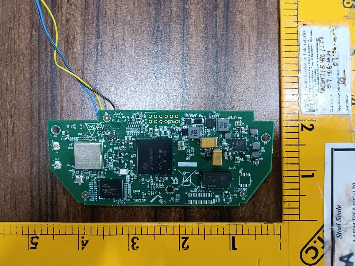
Click to zoom
Application Details
- Equipment Class
- DTS - Digital Transmission System
- Date of Grant
- Apr 13, 2022
- Application Purpose
- Original Equipment
- Date of Application
- Apr 13, 2022
- Equipment Note
- DataVINETM Mesh Card
- Frequency Range
- 2412.00000000 - 2462.00000000
- Country
- United States
Documents & Files
Document Text
Text extracted from the exhibit documents filed with the FCC. Open a document above to read the original.
Users Manual
1 FCC Test Manual for 11n Mesh Card Product Name: 11n Mesh Card for Delta Smart Grid Network Document Revision A0-01 Date 04-Feb-2022 11n Mesh Card FCC Test Manual Rev.A0-01 CONFIDENTIAL 2 TABLE OF CONTENTS 1. Introduction32. Hardware Specifications 33. IC marking of Mesh card 43.1 Top view of the Mesh card 4 3.2 Bottom View of Mesh Card 4 4. Mesh Card Power Supply Connection55. Antenna Port - U.FL Connector 76. UART TO USB Connection for Console 76.1 Connecting Mesh Card UART signals into U2UC Board 8 6.2 Console Using Tera Term Software 9 11n Mesh Card FCC Test Manual Rev.A0-01 CONFIDENTIAL 3 1. Introduction The Mesh Card is designed to interface with the Smart Electricity Meter as an Add- On Board Communication Module to enable the wireless data transfer capability for the Smart meter and also act as a wireless mesh network which is implemented under Wi-Fi 802.11a/b/g/n standard. It has been designed to operate in the dual-band Wi-Fi connectivity which supports IEEE 802.11a/b/g/n standard. The whole solution is implemented with the Texas Instruments AM437x (SoC) Applications processor and WiFi Module WL1837 from TI is used which supports Dual band 2.4GHz/5GHz Wi-Fi. 2. Hardware Specifications Parameter Description Processor and Wi-Fi module ● Processor: AM4378BZDN80 from Texas Instruments ● Wi-Fi Module: WL1837MODGI from Texas Instruments Memory ● DDR3 SDRAM - 128MBytes ● NAND Flash - 256MBytes Wi-Fi ● Dual-band IEEE802.11a/b/g/n ● Wi-Fi Radio Either 2×2 on 2.4GHz (or) 1×1 on 2.4GHz (or) 1x1 on 5GHz ● Wi-Fi Mesh and Wi-Fi hotspot simultaneous operation Power Supply ● In stand alone mode, Board can be powered by 12V DC(1A Current) or 4V DC(2A Current) Supply. Operating Temperature -40°C to 85°C 11n Mesh Card FCC Test Manual Rev.A0-01 CONFIDENTIAL 4 3. IC marking of Mesh card 3.1 Top view of the Mesh card The top side of the Mesh Card contains the Main Processor AM437XZDN, Wi-Fi Module WLAN/BT Module WL1837MODGI, DDR3, and PMIC. 3.2 Bottom View of Mesh Card The Bottom Side of the Mesh Card contains the IO connector (PCB Ref Des J5) used to provide a supply to the board and communicate with the meter over UART serial interface. 11n Mesh Card FCC Test Manual Rev.A0-01 CONFIDENTIAL 5 4. Mesh Card Power Supply Connection The Mesh card needs to be powered with the 4V supply from a Standard bench power supply using the cable assembly with DC Jack which should be connected to the IO Connector J5 on the board as shown in the above image. Note: The Red wire is for 4V and Black wire is for GND. Step:1 Connect the male header to the respective female header(J5) in the board. 11n Mesh Card FCC Test Manual Rev.A0-01 CONFIDENTIAL 6 ● Red color wire (4V supply pin) - PIN: 4 of J5 ● Black color wire (Ground pin) - PIN: 6 of J5 Note: J5 Header is present on the bottom side of the board. Step:2 Connect the 2 wires Red and Black from the Mesh card’s J5 connector using the male jumper to the Power supply. Note: Mesh Card be powered on using either with 12V or 4V supply. When 11n Mesh card is installed in the Vision Meter, the mesh card will be powered from 4V supply S.No Power Input to Mesh Card Connection to J5 Header 1 12V Input J5 Connector: Pin No 2 – 12V Pin No 6 – GND 2 4V Input J5 Connector: Pin No 4 – 4V Pin No 6 – GND LED Indication for Power ON/OFF status of Mesh Card: Note: The LED D16 will glow when Mesh Card is Power ON include one photo with meter as a final configuration 11n Mesh Card FCC Test Manual Rev.A0-01 CONFIDENTIAL 7 5. Antenna Port - U.FL Connector The 11n Mesh card supports WiFi 2.4GHz and 5GHz Radios. The dual band patch antenna is used and needs to be connected with the on-board U.FL connectors highlighted in the above image. S.No PCB Ref Des Frequency (GHz) Patch Antenna Part Number 1 J2 2.4GHz W3334B0150 2 J4 5GHz W3334B0150 6. UART TO USB Connection for Console NOTE: This U2UC console board is only for accessing console logs for testing purposes and this board will not be provided with the final product. 11n Mesh Card FCC Test Manual Rev.A0-01 CONFIDENTIAL 8 6.1 Connecting Mesh Card UART signals into U2UC Board The above image shows the connection of UART to the USB conversion board for accessing console logs. The Tx, Rx and GND pin needs to be connected to the respected marked circles in the H7 connector of the U2UC board. 11n Mesh Card FCC Test Manual Rev.A0-01 CONFIDENTIAL 9 Step 1: The UART signals are taken from the Test points of the Mesh card as follow, Signal Test Point Wire color UART Tx TP88 Blue UART Rx TP87 Yellow Gnd TP100 Black Step 2: The wires from the Mesh cards are connected to the UART to USB console board in header H4 as follows Signal Pin number in H4 Header Wire color Tx 2nd pin Yellow Rx 3rd pin Blue Gnd 4th pin Black Step 3: Short the 2nd and 3rd pin of H7 in UART to USB Console board Step 4: From the J1 connector connect the USB type B cable and connect the other end of the cable to the PC for the console. 6.2 Console Using Tera Term Software Steps to be followed after connecting the USB cable to your PC is given below, 11n Mesh Card FCC Test Manual Rev.A0-01 CONFIDENTIAL 10 STEP 1: After connecting the U2UC windows board to PC as mentioned in the Section 6 above, in the windows PC goto Start and open Open Tera Term. STEP 2: Please ensure that the Serial option is selected. Then Select the serial the COM Port: USB Serial Port is detected, then press OK. 11n Mesh Card FCC Test Manual Rev.A0-01 CONFIDENTIAL 11 STEP 3: Open Setup and select Serial port STEP 4: After clicking the serial port, select the speed as 115200 and then Click the new setting. 11n Mesh Card FCC Test Manual Rev.A0-01 CONFIDENTIAL 12 STEP 5: Please check for the console logs. Once the Mesh Card has booted up, below login credentials need to be provided to proceed further. Login: root Password: delta123 Note: Passwords will not be displayed in the console log screen, so please enter the correct password and press enter to proceed further. 11n Mesh Card FCC Test Manual Rev.A0-01 CONFIDE…
Text truncated - open the document above for the full version.
Cover Letter(s)
CONNECTIVITY simplified™ 29975 Technology Drive, Suite 101 Murrieta, CA 92563 www.deltaglobalnetwork.com Agent Authorization Company: Delta Energy & Communications, Inc. Address: 29975 Technology Drive, Suite 101 Murrieta, CA 92563 Product Name: DataVINE TM Mesh Card Model Number(s): DEC-O-A-701-10 Product Description: DataVINETM Mesh Card for use with Vision Smart Meters and 4V Supply. Ti Wi-Fi module. We authorize MiCOM Labs Inc., 575 Boulder Court, Pleasanton, California 94566, USA, to act on our behalf on all matters concerning the certification of above named equipment. We declare that MiCOM Labs Inc. is allowed to forward all information related to the approval and certification of equipment to the regulatory agencies as required and to discuss any issues concerning the approval application. Any and all acts carried out by MiCOM Labs on our behalf shall have the same effect as acts of our own. Signature: Date: 21-02-2022 Name: Scott M.Foster Title: Chairman/President/Chief Executive Officer Company: Delta Energy & Communications, Inc.
Cover Letter(s)
CONNECTIVITY simplified™ 29975 Technology Drive, Suite 101 Murrieta, CA 92563 www.deltaglobalnetwork.com Scott M.Foster President/CEO Delta Energy & Communications, Inc. Date: Thursday, February 3, 2022 Office of Engineering Technology Federal Communications Commission 7435 Oakland Mills Road Columbia, MD 21046 To: To Whom It May Concern Regarding: Request for Confidentiality, FCC ID: 2A3WGOA70110 Executive Summary Pursuant to the provisions of Sections 0.457 and 0.459 of Commission's rules (47CFR0.457, 0.459), we are requesting the Commission to withhold the following attachment(s) as confidential documents from public disclosure. Exhibits Long-Term Confidentiality Short-Term Confidentiality NOTE 2 ID Label/Location No No Attestation Statement No No External Photos No ☒ Block Diagram ☒ ☐ Schematics ☒ ☐ Test Report No No Test Setup Photos No ☒ User’s Manual ☒ NOTE 1 ☐ Internal Photos ☒ NOTE 1 ☐ Parts List / Tune Up ☒ ☐ United States (Murrieta) +1 951 816 6338 | South Africa (Cape Town) +27 21 276 1251 RF Exposure Info No No Operational Description ☒ ☐ Cover Letter(s) No No SDR Software / Security Info ☒ No NOTE 1: Long-Term Confidentiality may be permitted under special conditions (See II. LONG-TERM CONFIDENTIALITY, Section 3 of KDB 726920, use last in force) NOTE 2: Short-Term Confidentiality can be requested for a maximum of 180 days from the date of the grant. The above mentioned documents contain detailed system and equipment descriptions and are considered as proprietary information in operation of the equipment. The public disclosure of the above documents might be harmful to our company and would give competitors an unfair advantage in the market. In the case of short-term Confidentiality, the applicant requests the exhibits selected above are withheld from public view for a period of 180 days from the date of the Grant of Equipment Authorization and prior to marketing. It is our understanding that all measurement test reports, FCC ID label format and correspondent during certification review process cannot be granted as confidential documents and that information will be available for public review once the grant of equipment authorization is issued. Should you have any questions or comments regarding this matter, please contact me directly. Sincerely yours, Delta Energy & Communications, Inc 29975 Technology Drive, Suite 101 Murrieta, CA 92563 United States of America Scott M.Foster [email protected] +1(951)-816-6338 President/CEO 2
External Photos
Antenna Port Label on EUT
ID Label/Location Info
Label on EUT
Internal Photos
Antenna Port Label on EUT
RF Exposure Info
RF EXPOSURE EVALUATION 1.PRODUCTINFORMATION Product Description DataVINE TM Mesh Card Model Name DEC-O-A-701-10 FCC ID 2A3WGOA70110 2.EVALUATION METHODANDLIMIT Human exposure to RF emissions from mobile devices(47CFR§2.1091) may be evaluated based on the MPE limits adopted by the FCC for electric and magnetic field strength and/or power density, as appropriate, since exposures are assumed to occur at distances of 20 cm or more from persons. LIMITS FOR GENERAL POPULATIONIUNCONTROLLED EXPOSURE Frequency Range (MHz) E-field Strength (E) (V/m) Magnetic Field Strength (H) (A/m) Power Density(S) (mW/cm 2 ) Averaging Time IEl 2 IHl 2 or , S(Minutes) 0.3--1.34 614 1.63 (100)* 30 1.34--30 824/f 2.19/f (180/f 2 )* 30 30--300 27.5 0.073 0.2 30 300--1500 -- -- f/1500 30 1500--100,000 -- -- 1.0 30 *Note: 1.f= Frequency in MHz*Plane-wave Equivalent Power Density 2.The averaging time for General Population/Uncontrolled exposure to fixed transmitters is not applicable for mobile and portable transmitters. (operated in BT/ WIFI) See47CFR§§2.1091 and 2.1093 on source-based time-averaging requirement for mobile and portable transmitters. S=PG/4rrR 2 Where: S=power density P=power input toantenna G=power gain of the antenna in the direction of interest relative to anisotropic radiator R=distance to the center of radiation of the antenna 3.CALCULATION A minimum test separation distance 20cm is required between the antenna and radiating structures of the device and nearby persons to apply mobile device exposure limits. The distance must be at least 20cm and fully supported by the operating and installation configurations of the transmitter and its antenna(s), according to the source-based time-averaged maximum power requirements of §2.1091(d)(2). In cases where cable losses or other attenuations are applied to determine compliance, the most conservative operating configurations and exposure conditions must be evaluated. Antenna Gain (2.4GHz) = 4dBi (Numeric = 2.512), rr = 3.14 Antenna Gain (5GHz) = 2.5dBi (Numeric = 3.162), rr = 3.14 Frequency (MHz) Output Power (dBm) Output Power (mW) Power Density (mW/cm 2) Power Density Limit (mW/cm 2) 2437 (Wi-Fi) 24.03 252.92979964 0.126 1 5180 (Wi-Fi) Band 1 17.63 57.942869643 0.036 1 5785 (Wi-Fi) Band 4 18.41 69.342580602 0.043 1 Note: Only the worst case recorded.
Test Report
Report No.: AAEMT/EMC/220208-01-02 Page | 1 Plot No.174, UdyogVihar Phase 4, Sector -18, Gurgaon -122016, Haryana, India Contact: 0124-4235350, 4145343; e-mail: info @aaemtlabs.com; Website: www.aaemtlabs.com AA Electro Magnetic Test Laboratory Private Limited Certificate#5593.01 FCC Test Report Part 15 Subpart C FCC ID:2A3WGOA70110 Client Information: Applicant: Delta Energy & Communications, Inc Applicant add.: 29975 Technology Drive, Suite 101, Murrieta, CA 92563+19518166338, [email protected] Product Information: EUT Name: DataVINE TM Mesh Card Model No.: DEC-O-A-701-10 Brand Name: Serial Model: N/A Standards: FCC PART 15 Subpart C: 2015 section 15.247 AA Electro Magnetic Test Laboratory Private Limited Add. : Plot No 174, Udyog Vihar - Phase 4, Sector 18, Gurgaon, Haryana, India Date of Receipt: Feb. 08, 2022 Date of Test: Feb. 09 ~ Mar. 03, 2022 Date of Issue: Mar. 15, 2022 Test Result: Pass Declaration of Conformity: This device described above has been tested by AA Electro Magnetic Test Laboratory Private Limited, and the test results show that the equipment under test (EUT) is in compliance with the FCC requirements. And it is applicable only to the tested sample identified in the report. *This test report must not be used by the client to claim product endorsement by any agency of the U.S. government. Prepared By (+ signature) Abhinav Kumar: Reviewed & Approved by: (+ signature) Dr. Lenin Raja (Authorized Representative) (/ lenin83/) Declaration of conformity of the results is based as per the standard limits Report No.: AAEMT/EMC/220208-01-02 Page | 2 Plot No.174, UdyogVihar Phase 4, Sector -18, Gurgaon -122016, Haryana, India Contact: 0124-4235350, 4145343; e-mail: info @aaemtlabs.com; Website: www.aaemtlabs.com AA Electro Magnetic Test Laboratory Private Limited Certificate#5593.01 1 Contents Page COVER PAGE 1 CONTENTS 2 2 VERSION 3 3 TEST SUMMARY 4 3.1 COMPLIANCE WITH FCC PART 15 SUBPART C 4 3.2 MEASUREMENT UNCERTAINTY 5 3.3 TEST LOCATION 5 4 TEST FACILITY 6 4.1 DEVIATION FROM STANDARD 6 4.2 ABNORMALITIES FROM STANDARD CONDITIONS 6 5 GENERAL INFORMATION 7 5.1 GENERAL DESCRIPTION OF EUT 7 5.2 EUT PERIPHERAL LIST 9 5.3 TEST PERIPHERAL LIST 9 6 EQUIPMENTS LIST FOR ALL TEST ITEMS 10 7 TEST RESULT 12 7.1 DESCRIPTION OF TEST CONDITIONS 12 7.2 ANTENNA REQUIREMENT 13 7.3 CONDUCTION EMISSIONS MEASUREMENT 14 7.4 RADIATED EMISSIONS MEASUREMENT 18 7.5 6 DB BANDWIDTH 50 7.6 MAXIMUM PEAK OUTPUT POWER 63 7.7 PEAK POWER SPECTRAL DENSITY 66 7.8 BAND EDGES REQUIREMENT 75 7.9 CONDUCTED SPURIOUS EMISSIONS 89 Report No.: AAEMT/EMC/220208-01-02 Page | 3 Plot No.174, UdyogVihar Phase 4, Sector -18, Gurgaon -122016, Haryana, India Contact: 0124-4235350, 4145343; e-mail: info @aaemtlabs.com; Website: www.aaemtlabs.com AA Electro Magnetic Test Laboratory Private Limited Certificate#5593.01 2 Version Revision Record Version Chapter Date Modifier Remark -- -- -- -- -- -- -- -- -- -- -- -- -- -- -- -- -- -- -- -- Report No.: AAEMT/EMC/220208-01-02 Page | 4 Plot No.174, UdyogVihar Phase 4, Sector -18, Gurgaon -122016, Haryana, India Contact: 0124-4235350, 4145343; e-mail: info @aaemtlabs.com; Website: www.aaemtlabs.com AA Electro Magnetic Test Laboratory Private Limited Certificate#5593.01 3 Test Summary 3.1 Compliance with FCC Part 15 subpart C TEST TEST REQUIREMENT TEST METHOD RESULT Antenna Requirement FCC PART 15 C section 15.247 (c) and Section 15.203 FCC PART 15 C section 15.247 (c) and Section 15.203 PASS Conducted Emissions at Mains Terminals FCC PART 15 C section 15.207 ANSI C63.10: Clause 6.2 PASS Radiated Spurious Emission (30 MHz to 25 GHz) FCC PART 15 C section 15.209 &15.247(d) ANSI C63.10: Clause 6.4, 6.5 and 6.6 PASS 6 dB Bandwidth FCC PART 15 C section 15.247 (a)(2) ANSI C63.10: Clause 6.9.1 PASS Maximum Peak Output Power FCC PART 15 C section 15.247(b)(3) FCC/KDB-558074 D01 v03r01 Clause 9.1.2 PASS Peak Power Spectral Density FCC PART 15 C section 15.247(e) ANSI C63.10: Clause 6.11.2.3 PASS Band Edges Measurement FCC PART 15 C section 15.247 (d) &15.205 FCC/KDB-558074 D01 v03r01 Clause 13.3.1 PASS Conducted Spurious Emission (30MHz to 25GHz) FCC PART 15 C section 15.209 &15.247(d) ANSI C63.10: Clause 6.7 PASS Remark: N/A: not applicable. Refer to the relative section for the details. EUT: In this whole report EUT means Equipment Under Test. Tx: In this whole report Tx (or tx) means Transmitter. Rx: In this whole report Rx (or rx) means Receiver. RF: In this whole report RF means Radio Frequency. ANSI C63.10: the detail version is ANSI C63.10:2013 in the whole report. Report No.: AAEMT/EMC/220208-01-02 Page | 5 Plot No.174, UdyogVihar Phase 4, Sector -18, Gurgaon -122016, Haryana, India Contact: 0124-4235350, 4145343; e-mail: info @aaemtlabs.com; Website: www.aaemtlabs.com AA Electro Magnetic Test Laboratory Private Limited Certificate#5593.01 3.2 Measurement Uncertainty All measurements involve certain levels of uncertainties, the following measurements uncertainty Levels have estimated based on standards, the maximum value of the uncertainty as below: No. Item Uncertainty 1 Conducted Emission Test 2.67dB 2 Radiated Emission Test 3.06dB 3.3 Test Location All tests were performed at: AA Electro Magnetic Test Laboratory Private Limited Plot No 174, Udyog Vihar - Phase 4, Sector 18, Gurgaon, Haryana, India Tel.: +91-0124-4235350 Report No.: AAEMT/EMC/220208-01-02 Page | 6 Plot No.174, UdyogVihar Phase 4, Sector -18, Gurgaon -122016, Haryana, India Contact: 0124-4235350, 4145343; e-mail: info @aaemtlabs.com; Website: www.aaemtlabs.com AA Electro Magnetic Test Laboratory Private Limited Certificate#5593.01 4 Test Facility The test facility is recognized, certified or accredited by the following organizations: ILAC / NABL Accreditation No.: TC-8597 Three 3m Semi-Anechoic Chamber, 1 full-Anechoic chamber and 2 Shielding Rooms of AA Electro Magnetic Test Laboratory Private Limited have been registered by National Accreditation Board for Testing and Calibration Laboratories (NABL). IL…
Text truncated - open the document above for the full version.
Test Setup Photos
Test Setup photograph
Contact Information
Applicant
Scott M Foster(President/CEO)
Technical Contact
Test Firm
AA Electro Magnetic Test LaboratoryJackie Deng
[email protected]911244235350
Technical Specifications
| # | Rule Parts | Frequency Range | Power Output |
|---|---|---|---|
| 1 | 15C | 2.41 GHz - 2.46 GHz | 252.93 mW |