2A42UAYD-H001Constant Temperature And Humidity Heating Plate
HUNAN ANYADA BUILDING MATERIALS TECHNOLOGY CO.,LTD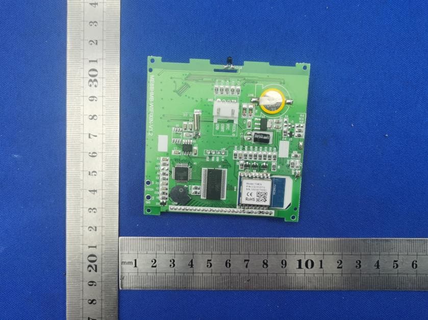
Click to zoom
Application Details
- Equipment Class
- DTS - Digital Transmission System
- Date of Grant
- Mar 02, 2022
- Application Purpose
- Original Equipment
- Date of Application
- Mar 01, 2022
- Equipment Note
- Constant Temperature And Humidity Heating Plate
- Frequency Range
- 2412.00000000 - 2462.00000000
- Country
- China
Documents & Files
Document Text
Text extracted from the exhibit documents filed with the FCC. Open a document above to read the original.
Users Manual
M 88AH Heating Thermostat Manual The thermostat is designed for control of electric heating devices (Built in sensors for measuring room temperature and external sensor for high temperature protection , to prevent heating device burned due to high temperature). Power Key : Touch the On / Off key to turn the system on or off. Mode Key :You can select “period control mode” or “manual mode” by this key. Up / Down key:Touch the Up and Down keys to set the temperature and adjust system parameters. And press Up and Down simultaneously and hold for 5 seconds to enter lock key function. Clock key: You can adjust the time and the week by this key. 1. Temperature sensor : NTC 2. Temperature accuracy : ±1°C 3.Power consumption : <1W4.Voltage: AC230V 50/60Hz 5. Load current : 3A/16A 6.Temperature setting : 5~90°C 7. Key : Touch key Manual mode: Set the temperature manually by this key. Automatic mode: Adjust to the automatic mode, the thermostat will work cyclically by week programming. Programming: 6 –event time and temperature In the shutdown state, long press mode key " " and the clock key " " for 5 seconds to enter programming mode. you can switch parameters by mode key. After entering the programming mode, press mode key to adjust " hour" ,then press mode key to adjust "minute".Press the mode key again to adjust temperature. 1 .Wake-up 2. Leave 3 Return(am) 4.Leave(pm) 5.Return(pm)6.Sleep Advanced setting (qualified person preferred) Press" M "and" "at the same time to enter the mode of advanced setting immediately when thermostat is turned off. The following seven functions can be chosen by" M "key. Anti-frozen function When the room temperature is below 5°C. when the room temperature is above 7°C, the thermostat will turn off the heating device automatically. In the state of shutdown, the thermostat will turn on the heating device automatically 1 2 3 4 -2 1°C ON Symbol Setting Default value or Temperature Switching Sensor mode Anti-frozen Adjust measured temperature range:-9~9°C Adjust switching differential range:1-5°C IN:built-in sensor OU:floor sensor IN Turn on(01)/off(00) Anti-frozen function calibration differential function of time mode 7 01 Kinds of periods 01:5+2 day mode 02:6+1 day mode 5 6 protection Overheating 60°C Adjust range:5°C~60°C 8 Max . temperature 40 Adjust range:30°C~90°C Set the lower limit of temperature 10 Adjust range:5°C~20°C Reset to factory settings 9 03:7 +0day mode 20°C 15°C 15°C 15°C 22°C 15°C Key Event Symbol Time Default value 01 02 03 04 05 06 01 02 Week day Weekend M 06: 00 08:00 11:30 12:30 17:00 22:00 08:00 23:00 Set time 15°C 22°C Set temperature OF : Close Application User Operation Technical data V V E AL:both sensor Mounting steps 1.Connect the power supply box according to the wiring diagram. 2.Push the panel up and take down the panel. 3.Install the fixed plate of thermostat in electrical connection box with screws. 4.Make the panel buckle to the fixed plate and push it down. Mounting Location Recommended The heating thermostat should be mounted on the wall with air flowing freely around. Warning: The mounting location should not be influenced by other heat source(e.g. sunlight), air flow through doors& windows or temperature of outer wall. Common failure handling Failure Handling Crash 1.Check the power supply wiring is correct or not . 2.Check the power key . LCD display garbled Display normal No output Remote failure Check if the remote control battery has enough power , if not replace the battery. Temperature display error Adjust the panel temperature display by the first option in the Advanced tab. Sensor failure 1.The shell is deformed after installation,can be reinstalled. 1. Check whether the wiring between the MPU and the power board is damaged. 2.Check whether the null line of live line is connected wrong. Check the sensor for damage Er1: Built-in sensor disconnected or fault with it. Er2 External sensor disconnected or fault with it. Main control circuit Potential-free output 1 2 3 4 ~ L ~ N ME 88H.03 ~ 3A ~ NO NC 1 2 1 2 3 4 ~ L ~ N ME 88H.16 ~ 16A ~ t°C Sensor β=3950 R25°C=10K 1 2 3 4 ~ L ~ N ME88H.31 ~ 3A ~ NONC 1 2 3A 1 2 t°C Sensor β=3950 R25°C=10K N1 L1 Wiring diagram 1-6 Period Icon description : Time Week Room Temp Touch key Setting Temp Locking key Heating Manual/Automatic Dimension 40mm 14mm 86mm 86mm 1)Thermostat networking steps: 2)Mobile phone networking steps: Before configuring WIFI , please make sure your phone is connected to 2.4GHz WIFI. 1. Use your mobile phone to scan the QR code below to download the”Tuya Smart ”app. China Foreign 2.Open the“Tuya Smart ” app and click “Add Device “as shown below. 3.After clicking”Small Home Appliances”, select “Thermostat”as shown below. 4.Click”confirm indicator rapidly blink”as shown below. 5.After entering the WIFI password, press”Confirm”as shown below. 6.The phone enters the device search and the connection mode is as shown below. 7.The mobile phone adds the device connection successfully, click”Done”as shown below. 8.Click on the”Done”button above to enter the control interface as shown below. 3)Device sharing instructions: 4.After entering the account number 1.Click” “as shown 2.Click”Share Device” 3.Click”Add Sharing” as shown below. as shown below. ,click”Done”as shown below. below. connection is successful. Please note that the router or the corresponding WiFi device is turned on and hear the buzzer ringing 3 sounds, the thermostat enters the distribution network interface. After the screen displays full display(or press the power button to exit)the thermostat has entered the network initialization status .When the WiFi symbol " " of the thermostat does not flash, it indicates that the within 5 meters of the thermostat. state (also the distribution network state). 4)Thermostat and mobile phone Exit the network: Press and hold the up and down button for about 5 seconds while the thermostat is off. When the buzzer sounds 3 times into the distribution network interface, the sc…
Text truncated - open the document above for the full version.
Cover Letter(s)
C5266091_X8_Ed.1 1/1 Letter of Authorization HUNAN ANYADA BUILDING MATERIALS TECHNOLOGY CO.,LTD Company: HUNAN ANYADA BUILDING MATERIALS TECHNOLOGY CO.,LTD Address: Wenchang Rd and Ziyang Blvd, Chang Chun Industrial Park,Yi Yang City,Hunan Prov. China Product Name: Constant Temperature And Humidity Heating Plate Model Number: AYD-H001 FCC Identifier: 2A42UAYD-H001 We authorize LGAI Technological Center S.A., Ronda de la Font del Carme, s/n, 08193 Bellaterra, Spain, to act on our behalf on all matters concerning the above named equipment. Any individual within LGAI Technological Center S.A. is authorized to act on our behalf and take action on the application. We declare that authorize LGAI Technological Center S.A., Ronda de la Font del Carme, s/n, 08193 Bellaterra, Spain, is allowed to forward all information related to the approval project to the Federal Communication Commission and to discuss any issues concerning the approval application. Any and all acts carried out by LGAI Technological Center S.A. on our behalf shall have the same effect as acts of our own. Name: Chen Kang Date: 2022.02.27 Title: GM Assistant Signature of applicant:
Cover Letter(s)
C5266091_X10_Ed.2 1/1 HUNAN ANYADA BUILDING MATERIALS TECHNOLOGY CO., LTD Office of Engineering Technology Federal Communications Commission 7435 Oakland Mills Road Columbia, MD 21046 Date: 2022.02.27 Subject: Request for Confidentiality FCC ID: 2A42UAYD-H001 To Whom It May Concern, Pursuant to the provisions of Sections 0.457 and 0.459 of Commission's rules (47CFR0.457, 0.459), we are requesting the Commission to withhold the following attachment(s) as confidential document from public disclosure. Exhibits Long-Term Confidentiality Short-Term Confidentiality NOTE 2 ID Label/Location No No Attestation Statement No No External Photos No ☐ Block Diagram ☒ ☐ Schematics ☒ ☐ Test Report No No Test Setup Photos No ☐ User’s Manual ☐ NOTE 1 ☐ Internal Photos ☐ NOTE 1 ☐ Parts List / Tune Up ☐ ☐ RF Exposure Info No No Operational Description ☒ ☐ Cover Letter(s) No No SDR Software / Security Info ☐ No NOTE 1: Long-Term Confidentiality may be permitted under special conditions (See II. LONG-TERM CONFIDENTIALITY, Section 3 of KDB 726920, use last in force) NOTE 2: Short-Term Confidentiality can be requested for a maximum of 180 days from the date of the grant. Above mentioned document contains detailed system and equipment description are considered as proprietary information in operation of the equipment. The public disclosure of above documents might be harmful to our company and would give competitor an unfair advantage in the market. In case of short-term Confidentiality, the applicant requests the exhibits selected above are withheld from public view for a period of ____45 __ days from the date of the Grant of Equipment Authorization and prior to marketing. It is our understanding that all measurement test reports, FCC ID label format and correspondent during certification review process cannot be granted as confidential documents and those information will be available for public review once the grant of equipment authorization is issued. C5266091_X10_Ed.2 1/1 Sincerely, Signature: Name: Chen Kang Title: GM Assistant
ID Label/Location Info
Model: AYD-H001 FCC ID: 2A42UAYD-H001 Label Location
Internal Photos
Internal Photos ANT
RF Exposure Info
Shenzhen CTB Testing Co., Ltd. FCC ID: 2A42UAYD-H001 Portable device According to §15.247(e)(i) and §1.1307(b)(1), systems operating under the provisions of this section shall be operated in a manner that ensures that the public is not exposed to radio frequency energy level in excess of the Commission’s guidelines. According to KDB447498 D01 General RF Exposure Guidance V06 The 1-g SAR and 10-g SAR test exclusion thresholds for 100 MHz to 6 GHz at test separation distances ≤ 50 mm are determined by: [(max. power of channel, including tune-up tolerance, mW)/(min. test separation distance, mm)]·[√f(GHZ)] ≤ 3.0 for 1-g SAR and ≤ 7.5 for 10-g extremity SAR, where: • f(GHZ) is the RF channel transmit frequency in GHz • Power and distance are rounded to the nearest mW and mm before calculation • The result is rounded to one decimal place for comparison When the minimum test separation distance is < 5 mm, a distance of 5 mm is applied to determine SAR test exclusion. 2.4wifi: Modulation Channel Freq. (GHz) Conduct ed power (dBm) Conducte d power (mW) Tune-up power (dBm) Max tune-up power (dBm) Max tune-up power (mW) Distance (mm) Result calculatio n SAR Exclusion threshold SAR test exclusion 2.4127.115.147.5±0.58.006.31<51.959833.00YES 2.447.335.417.5±0.58.006.31<51.971173.00YES 2.4627.175.217.5±0.58.006.31<51.980043.00YES 2.4126.614.587±0.57.505.62<51.746703.00YES 2.446.694.677±0.57.505.62<51.756813.00YES 2.4626.824.817±0.57.505.62<51.764713.00YES 2.4126.114.086.5±0.57.005.01<51.556753.00YES 2.446.554.527±0.57.505.62<51.756813.00YES 2.4626.354.326.5±0.57.005.01<51.572803.00YES 2.4125.753.766.0±0.56.504.47<51.387453.00YES 2.445.613.646.0±0.56.504.47<51.395483.00YES 2.4625.713.726.0±0.56.504.47<51.401763.00YES 802.11b 802.11g 802.11n( HT20) 802.11N( HT40) Conclusion: For the max result : 1.98004W/Kg ≤ FCC Limit 3.0 for 1g SAR.
Test Report
Shenzhen CTB Testing Technology Co., Ltd. Report No.: CTB220209007RF Report Tel: 4008-707-283 Web: http://www.ctb-lab.net Page 1 of 70 TEST REPORT Compiled by: Reviewed by: Approved by: Chen Zheng Arron Liu Bin Mei / Director The test report is effective only with both signature and specialized stamp. This result(s) shown in this report refer only to the sample(s) tested. Without written approval of Shenzhen CTB Testing Technology Co., Ltd. this report can’t be reproduced except in full. The tested sample(s) and the sample information are provided by the client. Product Name: Constant Temperature And Humidity Heating Plate FCC ID: 2A42UAYD-H001 Trademark: anyada Model Number: AYD-H001 Prepared For: HUNAN ANYADA BUILDING MATERIALS TECHNOLOGY CO., LTD Address: Wenchang Rd and Ziyang Blvd, Chang Chun Industrial Park,Yi Yang City,Hunan Prov. China Manufacturer: HUNAN ANYADA BUILDING MATERIALS TECHNOLOGY CO., LTD Address: Wenchang Rd and Ziyang Blvd, Chang Chun Industrial Park,Yi Yang City,Hunan Prov. China Prepared By: Shenzhen CTB Testing Technology Co., Ltd. Address: Floor 1&2, Building A, No. 26 of Xinhe Road, Xinqiao Community, Xinqiao Street, Baoan District, Shenzhen, Guangdong China Sample Received Date: Feb. 7, 2022 Sample tested Date: Mar.01.2022 to Mar.01.2022 Issue Date: Mar.01.2022 Report No.: CTB220209007RF Test Standards FCC Part15.247 ANSI C63.10:2013 Test Results PASS Remark: This is WIFI-2.4GHz band radio test report. Shenzhen CTB Testing Technology Co., Ltd. Report No.: CTB220209007RF Report Tel: 4008-707-283 Web: http://www.ctb-lab.net Page 2 of 70 TABLE OF CONTENT Test Report Declaration Page 1. VERSION............................................................ 4 2. TEST SUMMARY ..................................................... 5 3. MEASUREMENT UNCERTAINTY ....................................... 6 4. PRODUCT INFORMATION AND TEST SETUP ........................... 7 4.1 Product Information ..................................................... 7 4.2 Test Setup Configuration ................................................ 7 4.3 Support Equipment ..................................................... 7 4.4 Channel List ........................................................... 8 4.5 Test Mode ............................................................. 8 4.6 Test Environment ....................................................... 8 5. TEST FACILITY AND TEST INSTRUMENT USED ......................... 9 5.1 Test Facility ............................................................ 9 5.2 Test Instrument Used ................................................... 9 6. AC POWER LINE CONDUCTED EMISSION .............................. 12 6.1 Block Diagram Of Test Setup............................................ 12 6.2 Limit ................................................................. 12 6.3 Test procedure ........................................................ 12 6.4 Test Result ........................................................... 14 7. RADIATED SPURIOUS EMISSION ..................................... 16 7.1 Block Diagram Of Test Setup............................................ 16 7.2 Limit ................................................................. 16 7.3 Test procedure ........................................................ 17 7.4 Test Result ........................................................... 18 8. BAND EDGE AND RF COUNDUCTED SPURIOUS EMISSIONS ............ 40 8.1 Block Diagram Of Test Setup............................................ 40 8.2 Limit ................................................................. 40 8.3 Test procedure ........................................................ 40 8.4 Test Result ........................................................... 41 9. COUDUCTED OUTPUT POWER....................................... 49 9.1 Block Diagram Of Test Setup............................................ 49 9.2 Limit ................................................................. 49 9.3 Test procedure ........................................................ 49 9.4 Test Result ........................................................... 50 10. 6DB OCCUPIED BANDWIDTH ........................................ 55 10.1 Block Diagram Of Test Setup .......................................... 55 10.2 Limit ................................................................ 55 10.3 Test procedure ....................................................... 55 10.4 Test Result .......................................................... 55 11. POWER SPECTRAL DENSITY ........................................ 61 11.1 Block Diagram Of Test Setup .......................................... 61 11.2 Limit ................................................................ 61 11.3 Test procedure ....................................................... 61 Shenzhen CTB Testing Technology Co., Ltd. Report No.: CTB220209007RF Report Tel: 4008-707-283 Web: http://www.ctb-lab.net Page 3 of 70 11.4 Test Result .......................................................... 62 12. ANTENNA REQUIREMENT ........................................... 67 13. EUT PHOTOGRAPHS ................................................ 68 14. EUT TEST SETUP PHOTOGRAPHS ................................... 69 (Note: N/A means not applicable) Shenzhen CTB Testing Technology Co., Ltd. Report No.: CTB220209007RF Report Tel: 4008-707-283 Web: http://www.ctb-lab.net Page 4 of 70 1. VERSION Report N o. Issue Date Description Approved CTB220209007RF Mar.01.2022 Original Valid Shenzhen CTB Testing Technology Co., Ltd. Report No.: CTB220209007RF Report Tel: 4008-707-283 Web: http://www.ctb-lab.net Page 5 of 70 2. TEST SUMMARY The Product has been tested according to the following specifications: Test Item Test Requirement Test method Result AC Power Line Conducted Emission 47 CFR Part 15 Subpart C Section 15.207 ANSI C63.10-2013 PASS Radiated Spurious emissions 47 CFR Part 15 Subpart C Section 15.205/15.209 ANSI C63.10-201…
Text truncated - open the document above for the full version.
Test Report
Shenzhen CTB Testing Technology Co., Ltd. Report No.: CTB220209007RF Report Tel: 4008-707-283Web: http://www.ctb-lab.net Page 46 of 70 RF Conducted Spurious Emissions Graphs 802.11g /LCH 802.11g /MCH 802.11g /HCH Shenzhen CTB Testing Technology Co., Ltd. Report No.: CTB220209007RF Report Tel: 4008-707-283 Web: http://www.ctb-lab.net Page 47 of 70 RF Conducted Spurious Emissions Graphs 802.11n (HT20)/ LCH 802.11 n(HT20) /MCH 802.11 n(HT20) /HCH Shenzhen CTB Testing Technology Co., Ltd. Report No.: CTB220209007RF Report Tel: 4008-707-283 Web: http://www.ctb-lab.net Page 48 of 70 RF Conducted Spurious Emissions Graphs 802.11 n(HT40) /LCH 802.11 n(HT40) /MCH 802.11 n(HT40) /HCH Shenzhen CTB Testing Technology Co., Ltd. Report No.: CTB220209007RF Report Tel: 4008-707-283 Web: http://www.ctb-lab.net Page 49 of 70 9. COUDUCTED OUTPUT POWER 9.1 Block Diagram Of Test Setup 9.2 Limit FCC Part15 (15.247) , Subpart C Section Test Item Limit Frequency Range (MHz) Result 15.247(b)(3) Peak Output Power 1 watt or 30dBm 2400-2483.5 PASS 9.3 Test procedure 1. Remove the antenna from the EUT and then connect a low RF cable from the antenna port to the spectrum. 2. Set the spectrum analyzer: RBW =1MHz. VBW = 3MHz. Sweep = auto; Detector Function = Peak. Channel power function is used 3. Keep the EUT in transmitting at lowest, middle and highest channel individually. Record the max value. EUT Radio Test System Shenzhen CTB Testing Technology Co., Ltd. Report No.: CTB220209007RF Report Tel: 4008-707-283 Web: http://www.ctb-lab.net Page 50 of 70 9.4 Test Result Mode Channel. Peak Output Power [dBm] Limit[dBm] Verdict 802.11b LCH 7.11 30 PASS MCH 7.33 30 PASS HCH 7.17 30 PASS 802.11g LCH 6.61 30 PASS MCH 6.69 30 PASS HCH 6.82 30 PASS 802.11n(HT20) LCH 6.11 30 PASS MCH 6.55 30 PASS HCH 6.35 30 PASS 802.11n(HT40) LCH 5.75 30 PASS MCH 5.61 30 PASS HCH 5.71 30 PASS Shenzhen CTB Testing Technology Co., Ltd. Report No.: CTB220209007RF Report Tel: 4008-707-283 Web: http://www.ctb-lab.net Page 51 of 70 Mode Channel. Maximum Output Power [dBm] 802.11b LCH MCH HCH Shenzhen CTB Testing Technology Co., Ltd. Report No.: CTB220209007RF Report Tel: 4008-707-283 Web: http://www.ctb-lab.net Page 52 of 70 802.11g LCH MCH HCH Shenzhen CTB Testing Technology Co., Ltd. Report No.: CTB220209007RF Report Tel: 4008-707-283 Web: http://www.ctb-lab.net Page 53 of 70 802.11n(HT2 0) LCH MCH HCH Shenzhen CTB Testing Technology Co., Ltd. Report No.: CTB220209007RF Report Tel: 4008-707-283 Web: http://www.ctb-lab.net Page 54 of 70 802.11n(HT4 0) LCH MCH HCH Shenzhen CTB Testing Technology Co., Ltd. Report No.: CTB220209007RF Report Tel: 4008-707-283 Web: http://www.ctb-lab.net Page 55 of 70 10. 6DB OCCUPIED BANDWIDTH 10.1 Block Diagram Of Test Setup 10.2 Limit FCC Part15 (15.247) , Subpart C Section Test Item Limit Frequency Range (MHz) Result 15.247(a)(2) Bandwidth >= 500KHz (6dB bandwidth) 2400-2483.5 PASS 10.3 Test procedure 1. Rem1. Set RBW = 100 kHz. 2. Set the video bandwidth (VBW) ≥ 3 x RBW. 3. Detector = Peak. 4. Trace mode = max hold. 5. Sweep = auto couple. 6. Allow the trace to stabilize. 7. Measure the maximum width of the emission that is constrained by the frequencies associated with the two outermost amplitude points (upper and lower frequencies) that are attenuated by 6 dB relative to the maximum level measured in the fundamental emission. EUT Radio Test System Shenzhen CTB Testing Technology Co., Ltd. Report No.: CTB220209007RF Report Tel: 4008-707-283 Web: http://www.ctb-lab.net Page 56 of 70 10.4 Test Result Te s t Mode Frequency 6dB Bandwidth (MHz) Limit(kHz) Result 802.11b LCH 10.166 500 PASS MCH 11.093 500 PASS HCH 11.018 500 PASS 802.11g LCH 16.35 500 PASS MCH 16.344 500 PASS HCH 16.353 500 PASS 802.11n(HT20) LCH 17.593 500 PASS MCH 17.594 500 PASS HCH 17.587 500 PASS 802.11n(HT40) LCH 36.37 500 PASS MCH 36.366 500 PASS HCH 36.381 500 PASS Shenzhen CTB Testing Technology Co., Ltd. Report No.: CTB220209007RF Report Tel: 4008-707-283 Web: http://www.ctb-lab.net Page 57 of 70 Test Graph: Graphs 802.11b /LCH 802.11b /MCH 802.11b/HCH Shenzhen CTB Testing Technology Co., Ltd. Report No.: CTB220209007RF Report Tel: 4008-707-283 Web: http://www.ctb-lab.net Page 58 of 70 802.11g/LCH 802.11g/MCH 802.11g/HCH Shenzhen CTB Testing Technology Co., Ltd. Report No.: CTB220209007RF Report Tel: 4008-707-283 Web: http://www.ctb-lab.net Page 59 of 70 802.11n(HT20)/LC H 802.11n(HT20)/MC H 802.11n(HT20)/HC H Shenzhen CTB Testing Technology Co., Ltd. Report No.: CTB220209007RF Report Tel: 4008-707-283 Web: http://www.ctb-lab.net Page 60 of 70 802.11n(HT40)/LC H 802.11n(HT40)/MC H 802.11n(HT40)/HC H Shenzhen CTB Testing Technology Co., Ltd. Report No.: CTB220209007RF Report Tel: 4008-707-283 Web: http://www.ctb-lab.net Page 61 of 70 11. POWER SPECTRAL DENSITY 11.1 Block Diagram Of Test Setup 11.2 Limit FCC Part15 (15.247) , Subpart C Section Test Item Limit Frequency Range (MHz) Result 15.247 Power Spectral Density 8 dBm (in any 3KHz) 2400-2483.5 PASS 11.3 Test procedure 1. Set analyzer center frequency to DTS channel center frequency. 2. Set the span to 1.5 times the DTS bandwidth. 3. Set the RBW to: 3 kHz ≤ RBW ≤ 100 kHz. 4. Set the VBW ≥ 3 x RBW. 5. Detector = PEAK. 6. Sweep time = auto couple. 7. Trace mode = max hold. 8. Allow trace to fully stabilize. 9. Use the peak marker function to determine the maximum amplitude level within the RBW. 10. If measured value exceeds limit, reduce RBW (no less than 3 kHz) and repeat. EUT Radio Test System Shenzhen CTB Testing Technology Co., Ltd. Report No.: CTB220209007RF Report Tel: 4008-707-283 Web: http://www.ctb-lab.net Page 62 of 70 11.4 Test Result Mode Channel. Power Spectral Density [dBm /3KHz] Limit(8 dBm (in any 3KHz)) Verdict 802.11b LCH -21.931 8 PASS MCH -21.553 8 PASS HCH -22.074 8 PASS 802.11g LCH -25.742 8 PASS MCH -26.134 8 PASS HCH -26.458 8 PASS 802.11n(H T20) LCH -26.389 8 PASS MCH -25.892 8 PASS HCH -26.232 8 PASS 802.11n(H T40) LCH -29.985 8 PASS MCH -29.618 8 PASS HCH -30.83 8 P…
Text truncated - open the document above for the full version.
Test Setup Photos
Radiated Emission Below 1G Above 1G Conducted emissions
Contact Information
Applicant
Kang Chen(GM Assistant)
Technical Contact
Non-Technical Contact
Shenzhen CTB Testing Technology Co., Ltd.Simon Lee
[email protected](86) 13662574496
Test Firm
Shenzhen CTB Testing Technology Co., Ltd.Rita Xiao
[email protected]86-13538218145
Technical Specifications
| # | Rule Parts | Frequency Range | Power Output |
|---|---|---|---|
| 1 | 15C | 2.41 GHz - 2.46 GHz | 5.41 mW |