2A46S-HX160S7Power Bank
Dongguan Haoxun Electronic Technology Co., Ltd.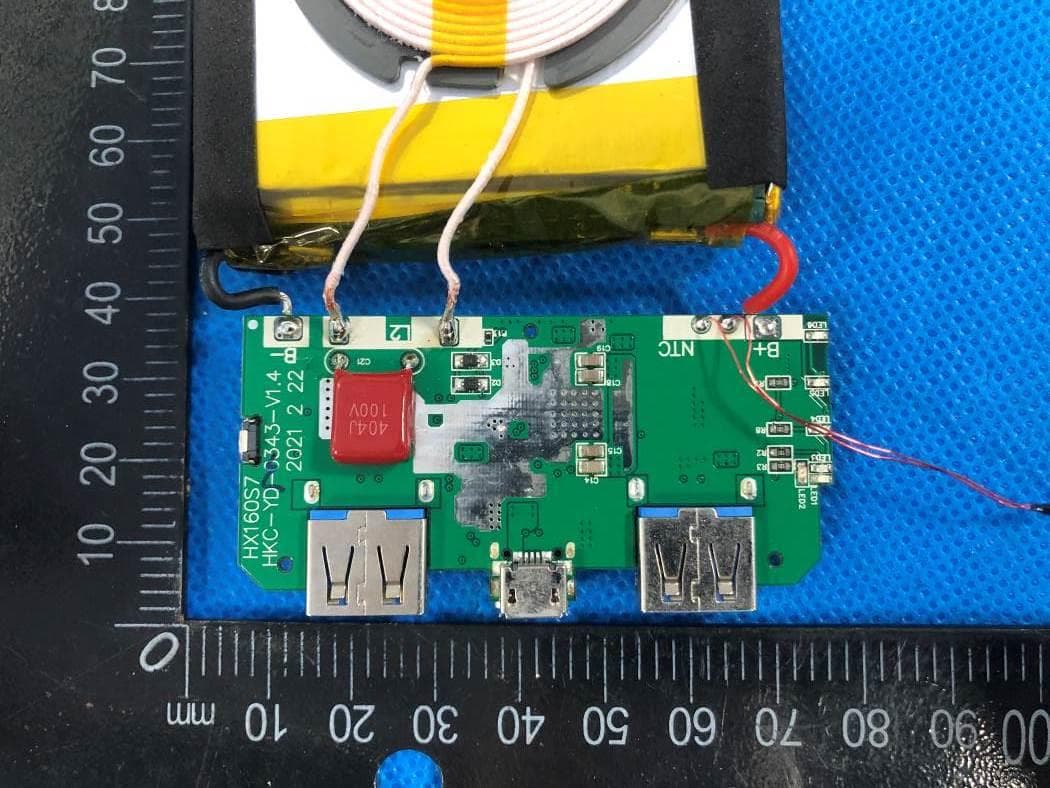
Click to zoom
Application Details
- Equipment Class
- 8CC - Part 18 Consumer Device
- Date of Grant
- Mar 23, 2022
- Application Purpose
- Original Equipment
- Date of Application
- Mar 23, 2022
- Equipment Note
- Power Bank
- Frequency Range
- 0.11000000 - 0.20500000
- Country
- China
Documents & Files
Document Text
Text extracted from the exhibit documents filed with the FCC. Open a document above to read the original.
Users Manual
Operation Instruction for Portable Power Source Please read this operation instruction before using the product. Product Ports Product Features Safety: With multiple protection designs, several abnormal conditions such as overcharge, overdischarge, high temperature and short circuit can be easily handled no matter in charging, discharging or standby state to provide reliable guarantee for your mobile phone and digital device. Efficiency: With quick charging and discharging efficiency, supporting quick charging and discharging, QC3.0、 PD3.0、5V2.1A、Qi 10W wireless charging intelligent output. intelligent output. ,Support smart input such as PD3.0, 5V / 2.1A Compatibility: embedded with intelligent USB charge controller, compatible with main stream mobile phone and digital device, supporting main stream quick charging and discharging device. Quality: high-quality Li-polymer electric core is selected with customized charging and discharging electric chip. Product Introduction Thank you for your selection. This product is a type of high-capacity portable power source with high quality Li-polymer electric core and customized charging and discharging electric chip, which performs well in safety, efficiency and compatibility, etc. Product model: HX160S7 Battery type: Li-polymer electric core Input parameter:Type-c:5V/2.1A,9V/2A,12V/1.5A(Max) Micro:5V/2.1A Output parameter: Type-c:5V/3A,9V/2A,12V/1.5A(Max) USB QC: 5V/3A,9V/2A/12V/1.5A(Max), USB2.1A:5V/2.1A Wireless charging output:5W 7.5W 10W(Max) Dimension: ~21.1×77.8×156.5mm Usage temperature: 0°C~45°C Product Operation Power Indicator Switch After the product stops working, the LED light will automatically turn off in about 35 seconds. To view the current remaining power of the product, you can tap the switch to re-light the LED light to view the current remaining power of the product ,gently and continuously press twice: stop charging . Charging Charge the product with a brand power adapter connection. LED light shows current battery charge while charging capacity Indicator light 0~25% 25~50% 50~75% 75~100% finished charging LED1 flicker bright bright bright bright Output This product uses a smart identification charging design. When the digital product is connected with a USB power cable, the digital product can be intelligently and automatically recognized, and the charging function can be activated. LED light shows current battery charge during charging Wireless charging function: align the position of the receiver of the digital product supporting wireless charging with the position of the wireless charging indicator of the mobile power supply, and start the charging function(The wireless charging is abnormal, there is a foreign object or the LED1 is red when it is fully charged). During the charging process, the LED indicator shows the current battery level. Notice ● Please fully charge this product before first usage. ● During the usage of this product, please lighten the screen of digital product and confirm that the charging connection label is correctly displayed to ensure that the product is in normal working condition. ● During the charging for this product or charging for digital product with this product, please select adaptive connecting line by yourself. ● If the LED light of this product goes out during the charging process of the digital product, it means that the battery of the product is low, please charge it immediately. ● During the wireless charging of the digital product, the red light of LED1 is on to indicate abnormal charging (foreign objects). Check whether the position of the receiver of the digital product corresponds to the position indicated by the mobile power wireless charging and whether there are other metal objects. LED2 flicker bright bright bright LED3 flicker bright bright LED4 bright bright capacity Indicator light low battery 0~25% 25~50% 50~75% 75~100% LED1 flicker bright bright bright bright LED2 bright bright bright LED3 bright bright LED4 bright ● During the connection between the digital product and this product, the digital product has priority to use the electric quantity of this product. ● When the digital product is fully charged, please take out the connecting line in time to avoid loss. ● If the product enters into protection status due to output short circuit or other reasons (LED has no display after pressing buttons), it can be recovered by charging activation via external charger. Warning Since this product contains Li-ion electric core, it’s forbidden to dismantle the product shell arbitrarily to avoid possible damage to electric core or other dangers. It’s forbidden to arbitrarily dismantle, squeeze, puncture this product or put it in short circuit, water, fire or exposed to an environment with a temperature higher than 60°C (140°F). FCC Statement This device complies with Part 18 of the FCC Rules. Operation is subject to the following two conditions: (1)This device may not cause harmful interference. (2)This device must accept any interference received, including interference that may cause undesired operation. 2. Changes or modifications not expressly approved by the party responsible for compliance could void the user’s authority to operate the equipment. Note:This equipment has been tested and found to comply with the limits for a class B digital device,pursuant to Part 18 of the FCC Rules. These limits are designed to provide reasonable protection against harmful interference in a residential installation. This equipment generates uses and can radiate radio frequence energy and,if not installed and used in accordance with the instructions,may cause harmful interference to radio communications.However,there is no guarantee that interference will not occur in a particular installation.if this equipmemt does cause harmful interference to radio or television reception,which can be determined by turning the equipment off and on,the user is encouraged to try to correct the interference …
Text truncated - open the document above for the full version.
Internal Photos
ANTENNA
RF Exposure Info
1 / 10 EUT Specification FCC ID: 2A46S-HX160S7 Characteristics Description Product Name Power Bank Model number HX160S7 Power Supply AC120V/60Hz for adapter Operating Frequency Range 110-205KHz Modulation Technique ASK Antenna Type Induction coil Device category Portable (<20cm separation) Mobile (>20cm separation) Others ___ Exposure classification Occupational/Controlled exposure (S = 5mW/cm2) General Population/Uncontrolled exposure (S=1mW/cm2) Antenna diversity Single antenna Multiple antennas Tx diversity Rx diversity Tx/Rx diversity Evaluation applied MPE Evaluation SAR Evaluation Applicable Standard: FCC Part 1(1.1310) ,Part 2(2.1091) and KDB 680106 D01 RF Exposure Wireless Charging Apps v03 Applicable Requirement: Three different categories of transmitters are defined by the FCC in OET Bulletin 65. These categories are fixed installation, mobile, and portable and are defined as follows: 2 / 10 Fixed Installations: fixed location means that the device, including its antenna, is physically secured at a permanent location and is not able to be easily moved to another location. Additionally, distance to humans from the antenna is maintained to at least 2 meters. Mobile Devices: a mobile device is defined as a transmitting device designed to be used in other than fixed locations and to be generally used in such a way that a separation distance of at least 20 centimeters is normally maintained between the transmitter's radiating structures and the body of the user or nearby persons. Transmitters designed to be used by consumers or workers that can be easily re-located, such as a wireless modem operating in a laptop computer, are considered mobile devices if they meet the 20 centimeter separation requirement. The FCC rules for evaluating mobile devices for RF compliance are found in 47 CFR §2.1091. Portable Devices: a portable device is defined as a transmitting device designed to be used so that the radiating structure(s) of the device is/are within 20 centimeters of the body of the user. Portable device requirements are found in Section 2.1093 of the FCC's Rules (47 CFR§2.1093). The FCC also categorizes the use of the device as based upon the user’s awareness and ability to exercise control over his or her exposure. The two categories defined are Occupational/ Controlled Exposure and General Population/Uncontrolled Exposure. These two categories are defined as follows: Occupational/controlled exposure limits apply in situations in which persons are exposed as a consequence of their employment provided those persons are fully aware of the potential for exposure and can exercise control over their exposure. Limits for occupational/controlled exposure also apply in situations when a person is transient through a location where occupational/controlled limits apply provided he or she is made aware of the potential for exposure. The phrase fully aware in the context of applying these exposure limits means that an exposed person has received written and/or verbal information fully explaining the potential for RF exposure resulting from his or her employment. With the exception oftransient persons, this phrase also means that an exposed person has received appropriate training regarding work practices relating to controlling or mitigating his or her exposure. Such training is not required for transient persons, but they must receive written and/or verbal information and notification (for example, using signs) concerning their exposure potential and appropriate means available to mitigate their exposure. The phrase exercise control means that an exposed person is allowed to and knows how to reduce or avoid exposure by administrative or engineering controls and work practices, such as use of personal protective equipment or time averaging of exposure. General population/uncontrolled exposure limits apply in situations in which the general public may be exposed, or in which persons who are exposed as a consequence of their employment may not be fully aware of the 3 / 10 potential for exposure or cannot exercise control over their exposure. Licensees and applicants are responsible for compliance with both the occupational/controlled exposure limits and the general population/uncontrolled exposure limits as they apply to transmitters under their jurisdiction. Licensees and applicants should be aware that the occupational/controlled exposure limits apply especially in situations where workers may have access to areas in very close proximity to antennas and access to the general public may be restricted. In lieu of evaluation with the general population/uncontrolled exposure limits, amateur licensees authorized under part 97 of this chapter and members of his or her immediate household may be evaluated with respect to the occupational/controlled exposure limits in this section, provided appropriate training and information has been provided to the amateur licensee and members of his/her household. Other nearby persons who are not members of the amateur licensee's household must be evaluated with respect to the general population/uncontrolled exposure limits. Test Procedure 1.EUT was placed on a table, and the measure probe was placed at a measurement distance of 0~10cm from the EUT to the center of the probe. 2.Power on the measuring probe, the EUT was set at the maximum field strength emission state. 3.The EUT was put in different directions (Left, Right, Front, Rear, Top and Bottom) toward to the measure probe.The distance from the EUT to the probe starts from 0cm, and measures every 2cm until the distance is 10cm. 4.Record the worst data of the different directions. Measuring Device And Test Equipment Used Equipment Manufacturer Model No. Serial No. Last Cal. Cal. Interval E-Field Probe(9kHz-30M Hz) Narda EHP-200A 180ZX11012 2022.01.19 1 Year 4 / 10 Description of Support Device adapter : Model number: CD217 Input: AC 100-240V, 50/60Hz Output: DC 9V/3A,DC 12V/2.5A iPhone : Manufacturer: Apple I…
Text truncated - open the document above for the full version.
Test Report
Report No.: E01A22020109F00501 1 of 30 DongGuan Anci Electronic Technology Co., Ltd 1-2 Floor, Building A, No.11, Headquarters 2 Road, Songshan Lake Hi-tech Industrial Development Zone, Dongguan City, Guangdong Pr., China. Phone: 86-769- 8507 5888; Fax: 86-769- 8507 5898 E-mail: [email protected] Rev. 1.0 ELECTROMAGNETIC EMISSIONS COMPLIANCE REPORTUNINTENTIONAL RADIATORS CERTIFICATION TO FCC PART 18 SUBPART C REQUIREMENT OF Power Bank Model No.: HX160S7 Trademark: swyop, aboe, ekrist, iposible, trswyop, HRTOJ FCC ID: 2A46S-HX160S7 Report No.: E01A22020109F00501 Issue Date: Mar. 01, 2022 Prepared for Dongguan Haoxun Electronic Technology Co., Ltd. Room 301, Building 1, No. 4, Shigu Longkou Road, Tangxia Town dongguan, Guangdong Province Prepared by Dong Guan Anci Electronic Technology Co., Ltd. 1-2 Floor, Building A, No.11, Headquarters 2 Road, Songshan, Lake Hi-tech Industrial Development Zone, Dongguan City, Guangdong Pr., China. This report shall not be reproduced, except in full, without the written approval of Dong Guan Anci Electronic Technology Co., Ltd. Report No.: E01A22020109F00501 2 of 30 TRF NO. FCC18/A Report No.: E01A22020109F00501 Ver.1.0 TABLE OF CONTENT Test Report Description Page 1. SUMMARY OF TEST RESULTS ................................................................................................................... 5 2. GENERAL INFORMATION ............................................................................................................................ 6 2.1. Description of Device (EUT) ........................................................................................................................... 6 2.2. Input / Output Ports......................................................................................................................................... 7 2.3. Independent Operation Modes ....................................................................................................................... 7 2.4. Test Manner .................................................................................................................................................... 7 2.5. Description of Test Facility .............................................................................................................................. 7 2.6. Test Software .................................................................................................................................................. 7 2.7. Description of Support Device ........................................................................................................................ 8 2.8. Measurement Uncertainty .............................................................................................................................. 8 3. MEASURING DEVICE AND TEST EQUIPMENT ......................................................................................... 9 3.1. For Power Line Conducted Emission Measurement ...................................................................................... 9 3.2. For Radiated Emission Measurement ............................................................................................................ 9 4. POWER LINE CONDUCTED EMISSION MEASUREMENT ...................................................................... 10 4.1. Block Diagram of Test Setup ........................................................................................................................ 10 4.2. Measuring Standard ..................................................................................................................................... 10 4.3. Power Line Conducted Emission Limits ....................................................................................................... 10 4.4. EUT Configuration on Measurement ............................................................................................................. 11 4.5. Operating Condition of EUT .......................................................................................................................... 11 4.6. Test Procedure ............................................................................................................................................. 12 4.7. Measuring Results ........................................................................................................................................ 12 5. RADIATED EMISSION MEASUREMENT ................................................................................................... 15 5.1. Block Diagram of Test Setup ........................................................................................................................ 15 5.2. Measuring frequency range .......................................................................................................................... 16 5.3. Radiated Emission Limits ............................................................................................................................. 16 5.4. EUT Configuration on Measurement ............................................................................................................ 17 5.5. Operating Condition of EUT ......................................................................................................................... 17 5.6. Test Procedure ............................................................................................................................................. 17 5.7. Measuring Results ........................................................................................................................................ 18 6. PHOTOGRAPHS ......................................................................................................................................... 23 6.1. Photos of Conducted Emission Measurement ............................................................................................. 23 6.2. Photos…
Text truncated - open the document above for the full version.
Contact Information
Applicant
Xie WeiPing
Technical Contact
DongGuan Anci Electronic Technology Co., Ltd.Kingbo Hu
[email protected]86-769- 8507 5888
1-2 Floor, Building A, No. 11, Headquarters 2 Road · Dongguan, Guangdong · China
Test Firm
Guangdong GTG Testing Technology Co., Ltd.Kingbo Hu
[email protected]86-769- 8507 5888
Technical Specifications
| # | Rule Parts | Frequency Range | Power Output |
|---|---|---|---|
| 1 | 18 | 0.11 MHz - 0.205 MHz | - |