2A4BRSWEDFITFit testing device for earplugs
SwedSafe AB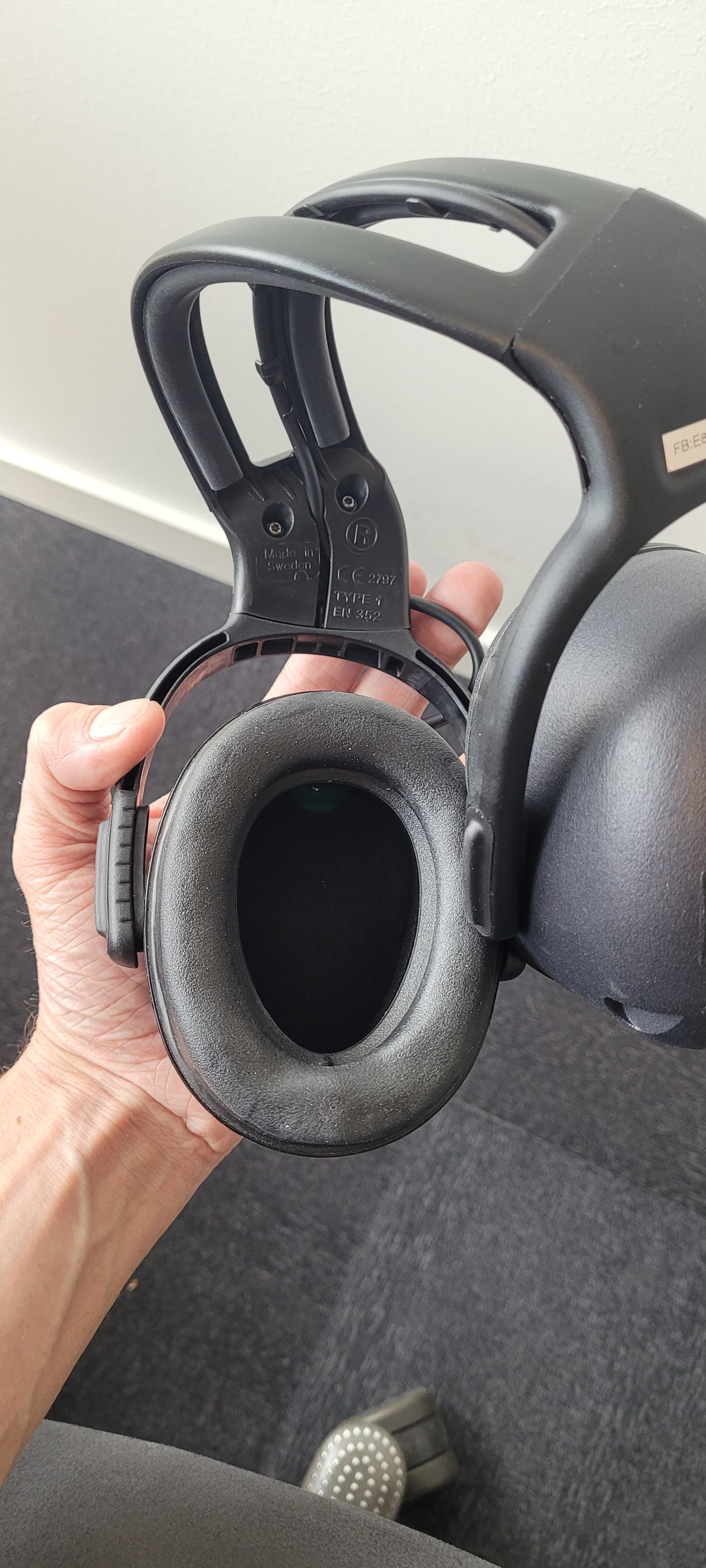
Click to zoom
Application Details
- Equipment Class
- DTS - Digital Transmission System
- Date of Grant
- May 10, 2023
- Application Purpose
- Original Equipment
- Date of Application
- May 09, 2023
- Equipment Note
- Fit testing device for earplugs
- Frequency Range
- 2402.00000000 - 2480.00000000
- Company
- SwedSafe AB
- Country
- Sweden
Documents & Files
Document Text
Text extracted from the exhibit documents filed with the FCC. Open a document above to read the original.
Users Manual
1 User instruction 2 Table of Contents Components .......................................................................................................................... 3 Packaging ............................................................................................................................... 4 Get started ............................................................................................................................. 6 Connecting to Wi-Fi ............................................................................................. 7 Location ............................................................................................................... 9 SwedFit app ......................................................................................................................... 10 Sign into the app ............................................................................................................ 11 Test selection ................................................................................................................. 14 Company ........................................................................................................... 14 Test person ........................................................................................................ 15 Work area .......................................................................................................... 16 Product to test ................................................................................................... 17 Scan for device................................................................................................... 19 How to wear the equipment .......................................................................................... 22 Practice .......................................................................................................................... 24 Testing ........................................................................................................................... 27 Result page .................................................................................................................... 31 Re-fit .................................................................................................................. 31 Generate report ................................................................................................. 32 Home ................................................................................................................. 35 Browse results ............................................................................................................... 35 FCC and IC Information .................................................................................................. 39 ISED (Innovation, Science and Economic Development Canada) ................................... 39 FAQ ................................................................................................................................ 40 Dictionary ...................................................................................................................... 41 Issue history................................................................................................................... 43 3 Tablet 1x Tablet charger 1x Headset 1x Extra battery for headset 1x set of 2 Universal travel adapter 1x 4 5 1 Start by taking out the tablet and flip front side of the case. 6 2 3 Unlock the sceen Press settings 7 4 5 Press ”Connections” Click on ”Wi-Fi” 8 6 7 Turn on Wi-fi and the tablet will start searching for available networks. Choose the network you want to connect to. Type in the network password and wait until it says “connected” and you see in the upper right corner. 9 8 9 Scroll down on the left side of the screen, until you see “Location”. Make sure “location” is turned on. 10 10 11 Return to the home screen by swiping from the bottom of the tablet upwards. Click on the SwedFit app. 11 12 13 Press: “Brand:” and choose Uvex or HexArmor. Choose Uvex or HexArmor 12 14 15 Press the row saying “Username” and type in your email address and the “Password” NOTICE! You need to get a login and password from SwedSafe. Press “Done” 13 16 Before signing in, press the “Remember me” button. After that, press “SIGN IN” 14 17 18 You are now in the “Test selection” page where you should fill in needed information. Start with “Select Company” First time using the app you need to create a new group. Press “NEW” and type in your company or work group. 15 19 20 “Select Test Person” → “NEW” 1. Add new person: Type the test person’s name, employee no. or unique ID. 2. “Notes” can be if the test person has a hearing loss or something else that ́s relevant. 3. Select which company employs the person.
Users Manual
16 21 22 1. Type in an existing work area. 2. Exposure level: The level of sound exposure in this work area. 3. Safety limit: Maximum sound exposure allowed under the protector. (Company or region exposure limit) 4. Required protection: If the exposure level and safety limit not are available it is possible to add “required protection level”. 17 23 Select the plug/product you want to test. The whole Uvex and HexArmor range are already added. 18 You can scroll down the list, or you can start typing the name of the product and it shows up. 19 24 Press “SCAN FOR DEVICE” to pair the headphones with the tablet. There will be a row saying “Swedfit” followed by a code for the headphones. 20 25 Connect to the headphones by selecting “Swedfit” and press “CONNECT”. Skip to the next step (26). If a “Swedfit” device do not appear; do the following steps: Check the batteries inside the left cup. Make sure the batteries are properly positioned. If so and you still do not see "Swedfit" device as an option, replace with new batteries. 21 To remove the batteries, pull the textile strap until they pop out. When you are going to place the batteries in the headphone, make sure the textile strap is underneath the batteries. (See picture) Start with the battery closest to you. (See picture) 22 26 Bring out the headphones 23 27 28 When step 13 – 23 is done, you can continue. Place the headphones on your ears. There is a left and right side to the headphones. Check for proper positioning by referencing the "L" and "R" labels on the outside of the cups. Place the tablet in front of you. Now you are ready to start. 24 29 30 A practice test must be performed for all new test subjects in order to determine their hearing threshold. To complete this test, select “Practice”. Now you should change the level of the sound by pressing “Decrease” and “Increase” to a level where you find your hearing threshold (the point at which the sound is just audible). 25 31 When you ́ve found your hearing threshold, press “Next” to continue. Press “OK”. Repeat practice test a second time. 26 32 33 The result of the practice is now shown on the screen. This result should be ± 4 dB. If you are outside of this range, you need to do another practice. Press: “OK” to continue. Find your hearing threshold one more time. Then press “Next”. 27 34 After the practice you should understand how the test works and are ready for testing. “Start without earplugs”: Find your hearing threshold without earplugs → insert earplugs and find the threshold again. “Start with earplugs inserted”: Find your hearing threshold with earplugs inserted → remove the earplugs and find the threshold again. 28 35 Find your hearing threshold without earplugs, like in the practice. When that’s done, press “NEXT”. 29 36 Insert earplugs. Follow the instructions. NOTE: If using foam earplugs, please allow 45 seconds for them to fully expand. 30 37 38 Find your hearing threshold with earplugs inserted. When that’s done, press “NEXT”. If you can ́t hear the signal, press increase. Wait for the earplugs to expand properly before going to the next step. For next step, press anywhere on the screen. 31 39 40 DONE! If you ́re not satisfied with your result you can re-fit the plug. Press “RE-FIT”. This will take you on step back, let you insert the plug again and find the threshold one more time. 32 41 42 When a test is done you ́re able to generate a report, based on the test. NOTE: You’re not able to generate a report later on. All reports that are generated on this tablet will be saved in the folder “SwedFit” on the home screen. 33 43 By going into the folder on the home screen, you can see all reports that have been saved. Choose the one you want to see. If you want to print the report, use the charging cable for the tablet and plug it in to your computer. Find the tablet on the computer and go into the folder “Swedfit”. 34 44 35 45 46 If you go back to the SwedFit application you will still be on the result page. Press “HOME” to get back to the home page in the app. If you want to see all previous tests done. Press “BROWSE RESULTS” 36 47 48 You should now see all previous tests which have been saved. To show more detailed information about a specific test. Press . 37 49 You are now able to see all relevant information about the selected test. You can delete the test by pressing “Delete test”. If you want to go back, press the “X” button. 38 50 51 To filter test results, press "Filter". Press on the row you want to use as filter. Type or choose from the list and press the button to apply the chosen filter. 39 FCC AND IC INFORMATION This equipment has been tested and found to comply with the limits for a Class B digital device, pursuant to Part 15 of the FCC Rules. These limits are designed to provide reasonable protection against harmful interference in a residential installation. This equipment generates uses and can radiate radio frequency energy and, if not installed and used in accordance with the instructions, may cause harmful interference to radio communications. However, there is no guarantee that interference will not occur in a particular installation. If this equipment does cause harmful interference to radio or television reception, which can be determined by turning the equipment off and on, the user is encouraged to try to correct the interference by one of the following measures: • Reorient or relocate the receiving antenna. • Increase the separation between the equipment and receiver. • Connect the equipment into an outlet on a circuit different from that to which the receiver is connected. • Consult the dealer or an experienced radio/TV technician for help. This device contains licence-exempt transmitter(s)/receiver(s) that comply with Innovation, Science and Economic Development Canada’s licence-exempt RSS(s). Operation is subject to the following two conditions: 1. This device may not cause interference. 2. This device must accept any interference, including i…
Text truncated - open the document above for the full version.
Attestation Statements
Covered Equipment Certification Attestation Letter 4/28/2023 Nemko North America, Inc. 303 River Road Ottawa K1V 1H2 Canada ATTN.: Reviewing Engineer FCC ID: 2A4BR-SwedFit SwedSafe AB (“the applicant”) certifies that the equipment for which authorization is sought is not “covered” equipment prohibited from receiving an equipment authorization pursuant to section 2.903 of the FCC rules. Note: If the equipment for which the applicant seeks authorization is produced by any of the entities identified on the current Covered List, the applicant should include an explanation on why the equipment is not “covered” equipment. SwedSafe AB (“the applicant”) certifies that, as of the date of the filing of the application, the applicant is not identified on the Covered List as an entity producing “covered” equipment. Signed: Printed name: Peter Franzen Title: Senior Technical Specialist Company Name: SwedSafe AB Date: 4/28/2023
Attestation Statements
* the applicant must designate a contact located in the United States for purposes of acting as the applicant’s agent for service of process, regardless of whether the applicant is a domestic or foreign entity. An applicant located in the United States may designate itself as the agent for service of process. U.S. Agent Designation for Service of Process - Certification Attestation Letter May 9, 2023 Nemko North America, Inc. 303 River Road Ottawa K1V 1H2 Canada ATTN.: Reviewing Engineer FCC ID: 2A4BRSWEDFIT Per section 2.911(d)(7) of the FCC rules, SwedSafe AB (“t he applicant”) certifies that the equipment for which authorization is sought is designated to the following U.S. Designated agent* for service of process: Company Name: HexArmor Physical U.S. Company Address: 640 Leffingwell AVE NE, Grand Rapids, Michigan 49505, USA Agent name: Lana Schuiteman Agent Email Address: [email protected] FRN: 0031860976 The above contact person accepts the obligation for service of process. The applicant accepts to maintain an agent for no less than one year after the grantee has terminated all marketing and importation or the conclusion of any Commission-related proceeding involving the equipment. Applicant Signed: Designated Agent Signed: (Required, if different to Applicant): Signed: Signed: Printed name: Peter Franzen Printed name: Lana Schuiteman Title: Senior Technical Specialist Title: International Trade Compliance Manager Company Name: SwedSafe AB Company Name: HexArmor Date: April 28, 2023 Date: May 9, 2023
Cover Letter(s)
6/14/2022 Nemko North America, Inc. 303 River Road Ottawa, Ontario, Canada K1V 1H2 AUTHORITY TO ACT AS AGENT - FCC On our behalf, I appoint Click or tap here to enter text., to act as our agent in the preparation of this application for equipment certification. I certify that submitted documents properly describe the device or system for which equipment certification is sought. I also certify that each unit manufactured, imported or marketed, as defined in FCC regulations will have affixed to it a label identical to that submitted for approval with this application. In signing this letter, Applicant certifies that neither the applicant nor any party to the application is not subject to a denial of Federal benefits, that include FCC benefits, pursuant to Section 5301 of the Anti- Drug Abuse Act of 1988, 21 U.S.C. § 862 because of a conviction for possession or distribution of a controlled substance. See 47 CFR 1.2002(b) for the definition of a "party" for these purposes. For instances where our authorized agent signs the application for certification on our behalf, I acknowledge that all responsibility for complying with the terms and conditions for certification, as specified by Nemko North America Inc., still resides still resides with us. Sincerely, Printed name: Peter Franzen
Cover Letter(s)
6/9/2022 SwedSafe AB, Nordanväg 7, SE-282 35 Tyringe Sweden REQUEST FOR CONFIDENTIALITY - FCC FCC ID: 2A4BR-SwedFit Pursuant to Sections 0.457(d)(1)(ii) and 0.459 of the Commission’s Rules and FCC Guidance document 726920, we hereby request confidential treatment of information accompanying this application as outlined below: PERMANENT LONG-TERM CONFIDENTIALITY: Schematics Bill of Materials/Parts List Block Diagrams Theory of Operation SHORT TERM CONFIDENTIALITY FOR A PERIOD OF 180 DAYS (Note: for the X number of days, you can list up to 180 days, but should not go past the date you start product marketing/sale): Internal Photos External Photos User Manual Test Set-up Photographs When the device is marketed before the requested number of days listed above, the grantee will inform the TCB to release the Short-Term Confidentiality information withheld on the FCC equipment authorization website. The above information contains trade secrets and proprietary information not customarily released to the public. The public disclosure of this information might be harmful to the applicant and provide unjustified benefits to its competitors. The Applicant understands that pursuant to Rule 0.457(d)(1)(ii), disclosure of this Application and all accompanying materials will not be made before the date of the Grant for this Application. Sincerely, Signed: Printed name: Peter Franzén Title: Management System Manager
RF Exposure Info
FCC ID: 2A4BRSWEDFIT FCC 1.1307(b)(3)(i)(B) Determination of Exemption for Single RF Sources Average Output Power, Conducted 0.75 mW Average Output Power, Radiated 0.03 mW Separation Distance d (cm)(valid for d ≤ 40 cm) d (cm) 0.00 cm Frequency f (GHz) (valid for f ≥ 300MHz and f ≤ 6 GHz) f (GHz) 2.40 GHz ERP @20cm (mW) ERP 20cm 3060 value used in Threshold calculation x 1.90 Threshold value at Separation distance d (mW) P th (mW) 1.00 mW Verdict: EXEMPTED Values above are valid for Single Source RF transmi tters Valid when available maximum time-averaged power or ERP is less than or equal to the Threshold Only valid for frequency ≥300MHz and ≤6GHz, not valid for other frequencies Valid for Separation Distance ≤40cm. Alternatively, use values in FCC 1.1307 Tabl e 1. Threshold Value is 1 mW for separation distance les s than 0.5cm
Test Report
ABRACON IS ISO9001-2015 CERTIFIED Hidden Creek Ln Spicewood TX 78669 5101 Phone: 512-371-6159 | Fax: 512-351-8858 REVISED: 11-01-22 For terms and conditions of sales, please visit: www.abracon.com OnBoard 2.4 GHz SMD - Antenna PRO-OB-440 13.75 x 5.23 x 3.53 mm RoHS/RoHS II Compliant MSL Level = 1 Request Samples Check Inventory Features • Compact • Low Cost • Mixed Linear Polarization • Peak Gain of less than 5 dBi • Efficiency > 65% • Surface Mount • Durable-Shelf life of up to 10 years Applications • 2.4 GHz - Wi-Fi/BT/BLE/ZigBee/ISM • IoT, M2M o Industrial IoT o Consumer IoT o Medical IoT • Telemetry • Wireless Remote Control • Personal Area Networks (PAN) • Industrial/Commercial Equipments Product Image ABRACON IS ISO9001-2015 CERTIFIED Hidden Creek Ln Spicewood TX 78669 5101 Phone: 512-371-6159 | Fax: 512-351-8858 REVISED: 11-01-22 For terms and conditions of sales, please visit: www.abracon.com OnBoard 2.4 GHz SMD - Antenna PRO-OB-440 13.75 x 5.23 x 3.53 mm RoHS/RoHS II Compliant MSL Level = 1 Request Samples Check Inventory Electrical Specification Note: All measurements were conducted on the evaluation board in free space. Performance will vary depending on the ground plane, application, and environment. Mechanical Specification Environmental Specification Parameter Specification Unit Operating Frequency 2400 - 2500 MHz Center Frequency 2450 Return Loss ˂ -6.9 dB Polarization Mixed Linear - Maximum Gain < 5.0 dBi Efficiency > 65 % Impedance 50 Ω Parameter Specification Antenna Dimension 13.75 x 5.23 x 3.53 mm Evaluation board Dimension 100 x 50 mm Mounting Type Surface Mount Parameter Specification Operating Temperature -40°C to +125°C Storage Temperature Maximum Temperature 400°C RoHS Compliance Yes Compliant with EU directive 2011/65/EU and 2015/863 Shelf life 10 years MSL Level 1, unlimited Mechanical resistance Immunity to vibrations IEC/EN 60068-2-6, Fc test Immunity to shock IEC/EN 60068-2-27, Ea test ABRACON IS ISO9001-2015 CERTIFIED Hidden Creek Ln Spicewood TX 78669 5101 Phone: 512-371-6159 | Fax: 512-351-8858 REVISED: 11-01-22 For terms and conditions of sales, please visit: www.abracon.com OnBoard 2.4 GHz SMD - Antenna PRO-OB-440 13.75 x 5.23 x 3.53 mm RoHS/RoHS II Compliant MSL Level = 1 Request Samples Check Inventory Product Dimension Unit : mm Antenna pins and keep-out block Unit : mm ABRACON IS ISO9001-2015 CERTIFIED Hidden Creek Ln Spicewood TX 78669 5101 Phone: 512-371-6159 | Fax: 512-351-8858 REVISED: 11-01-22 For terms and conditions of sales, please visit: www.abracon.com OnBoard 2.4 GHz SMD - Antenna PRO-OB-440 13.75 x 5.23 x 3.53 mm RoHS/RoHS II Compliant MSL Level = 1 Request Samples Check Inventory PCB layout and antenna pin numbering The antenna uses PIFA technology and should thus be mounted on a ground plane. If there are several layers in the PCB, there is an advantage to add vias for smooth interconnection of the ground areas to avoid splits in the ground plane. It is also important that there is a ground clearance around the NC pads and the RF feed pad, through all layers of the PCB. It is recommended to implement a matching network to optimize the antenna impedance in your application. The components can be positioned under the antenna. See recommendations in the figures below. Pin configuration PCB Layout (from evaluation board) Clearance through all layers Unit : mm ABRACON IS ISO9001-2015 CERTIFIED Hidden Creek Ln Spicewood TX 78669 5101 Phone: 512-371-6159 | Fax: 512-351-8858 REVISED: 11-01-22 For terms and conditions of sales, please visit: www.abracon.com OnBoard 2.4 GHz SMD - Antenna PRO-OB-440 13.75 x 5.23 x 3.53 mm RoHS/RoHS II Compliant MSL Level = 1 Request Samples Check Inventory Measurement Setup The antenna measurements were all done in free space with the OnBoard SMD 2400 evaluation board (PRO-EB-450) that has a PCB size of 100 x 50 mm. ABRACON IS ISO9001-2015 CERTIFIED Hidden Creek Ln Spicewood TX 78669 5101 Phone: 512-371-6159 | Fax: 512-351-8858 REVISED: 11-01-22 For terms and conditions of sales, please visit: www.abracon.com OnBoard 2.4 GHz SMD - Antenna PRO-OB-440 13.75 x 5.23 x 3.53 mm RoHS/RoHS II Compliant MSL Level = 1 Request Samples Check Inventory Reflection Characteristics – Return Loss Total Radiation Efficiency Maximum Radiation Gain ABRACON IS ISO9001-2015 CERTIFIED Hidden Creek Ln Spicewood TX 78669 5101 Phone: 512-371-6159 | Fax: 512-351-8858 REVISED: 11-01-22 For terms and conditions of sales, please visit: www.abracon.com OnBoard 2.4 GHz SMD - Antenna PRO-OB-440 13.75 x 5.23 x 3.53 mm RoHS/RoHS II Compliant MSL Level = 1 Request Samples Check Inventory Radiation Characteristics – 2D Pattern (2400 MHz) VP: Vertical Polarization HP: Horisontal Polarization Unit: dBi ABRACON IS ISO9001-2015 CERTIFIED Hidden Creek Ln Spicewood TX 78669 5101 Phone: 512-371-6159 | Fax: 512-351-8858 REVISED: 11-01-22 For terms and conditions of sales, please visit: www.abracon.com OnBoard 2.4 GHz SMD - Antenna PRO-OB-440 13.75 x 5.23 x 3.53 mm RoHS/RoHS II Compliant MSL Level = 1 Request Samples Check Inventory Radiation Characteristics – 2D Pattern (2500 MHz) VP: Vertical Polarization HP: Horisontal Polarization Unit: dBi ABRACON IS ISO9001-2015 CERTIFIED Hidden Creek Ln Spicewood TX 78669 5101 Phone: 512-371-6159 | Fax: 512-351-8858 REVISED: 11-01-22 For terms and conditions of sales, please visit: www.abracon.com OnBoard 2.4 GHz SMD - Antenna PRO-OB-440 13.75 x 5.23 x 3.53 mm RoHS/RoHS II Compliant MSL Level = 1 Request Samples Check Inventory Evaluation Board Outline & Matching Circuit The evaluation board (PRO-EB-450) is developed to simplify antenna testing and evaluation. It has an arbitrary size of 100 x 50 mm and includes an SMA connector. The purpose is to give a reference design for an optimal antenna implementation. The evaluation board can also be used to test other implementations by cutting and soldering the PCB into any device. Evaluation board outline The evaluation board has a matching circuit implemented next to the a…
Text truncated - open the document above for the full version.
Test Report
Report No. 449455-03-R00 Template version: C Nemko Group Nemko Scandinavia AS, Instituttveien 6, P.O. Box 96, 2027 Kjeller, Norway TEL +47 22 96 03 30 EMAIL [email protected] nemko.com/no Test Report Product Hearing Protection with Bluetooth Low Energy Name and address of the applicant Swedsafe AB Nordanväg 7 282 35 Tyringe, Sweden Name and address of the manufacturer Swedsafe AB Nordanväg 7 282 35 Tyringe, Sweden Model Swedfit Rating 3V DC (2x AA cells) Trademark Swedsafe Serial number See page 3 Additional information Bluetooth Low Energy Tested according to FCC Part 15.247 Digital Transmission Systems Industry Canada RSS-247, Issue 2 Digital Transmission Systems (DTSs), Frequency Hopping Systems (FHSs) and Licence-Exempt Local Area Network (LE-LAN) Devices Order number 449455 Tested in period 2021-11-18 to 2022-01-19 Issue date 2022-07-13 Name and address of the testing laboratory Instituttveien 6 Kjeller, Norway www.nemko.com CAB Number: FCC: NO0001 ISED: NO0470 An accredited technical test executed under the Norwegian accreditation scheme Prepared by [Frode Sveinsen] Approved by [G.Suhantakumar] This report shall not be reproduced except in full without the written approval of Nemko. Opinions and interpretations expressed within this report are not part of the current accreditation. This report was originally distributed electronically with digital signatures. For more information contact Nemko. TEST REPORT FCC Part 15.247 Report no.: 449455-03-R00 FCC ID: 2A4BRSWEDFIT IC: 28161-SWEDFIT Nemko Norway, Instituttveien 6, Kjeller, Norway Page 2 (30) Revision history Revision Date Comment Sign 00 2022-01-19 First edition FS THIS TEST REPORT APPLIES ONLY TO THE ITEM(S) AND CONFIGURATIONS TESTED. Deviations from, additions to, or exclusions from the test specifications are described in “Summary of Test Data”. Nemko Group authorizes the above-named entity to reproduce this report provided it is reproduced in its entirety and for use by the entity’s employees only. Any reproduction of parts of this report requires approval in writing from Nemko Group. Any use that a third party makes of this report, or any reliance on or decisions to be made based on it, are the responsibility of such third parties. Nemko Group accepts no responsibility for damages suffered by any third party caused by decisions made or actions based on this report. TEST REPORT FCC Part 15.247 Report no.: 449455-03-R00 FCC ID: 2A4BRSWEDFIT IC: 28161-SWEDFIT Nemko Norway, Instituttveien 6, Kjeller, Norway Page 3 (30) CONTENTS 1 INFORMATION ......................................................................................................................... 4 1.1 Test Item ................................................................................................................................................... 4 1.2 Normal test condition ................................................................................................................................. 5 1.3 Test Engineer(s) ........................................................................................................................................ 5 1.4 Antenna Requirement ................................................................................................................................ 5 1.5 EUT Operating Modes ............................................................................................................................... 5 1.6 Comments ................................................................................................................................................. 5 2 TEST REPORT SUMMARY ...................................................................................................... 6 2.1 General ..................................................................................................................................................... 6 2.2 Test Summary ........................................................................................................................................... 6 3 TEST RESULTS ........................................................................................................................ 7 3.1 Occupied Bandwidth (99% BW) ................................................................................................................. 7 3.2 DTS Bandwidth ......................................................................................................................................... 9 3.3 Peak Power Output ................................................................................................................................. 11 3.4 Conducted Emissions at Antenna Connector ........................................................................................... 13 3.5 Restricted Bands of operation .................................................................................................................. 16 3.6 Radiated Emissions, Band Edge.............................................................................................................. 17 3.7 Radiated Emissions, 30 – 1000 MHz. ...................................................................................................... 19 3.8 Radiated Emissions, 1 – 26 GHz ............................................................................................................. 21 3.9 Power Spectral Density (PSD) ................................................................................................................. 25 4 Measurement Uncertainty ..................................................................................................... 27 5 LIST OF TEST EQUIPMENT................................................................................................... 28 6 BLOCK DIAGRAM .................................................................................................................. 29 6.1 Power Line Conducted Emission .......................…
Text truncated - open the document above for the full version.
Test Setup Photos
TEST SET-UP PHOTOS Project no.: 449455 FCC ID: 2A4BRSWEDFIT Page 1 (1) Radiated Emissions 30 – 1000 MHz Radiated Emissions 1 – 18 GHz
Contact Information
Applicant
Peter Franzen(Management System Manager)
Test Firm
Nemko Scandinavia ASFrode Sveinsen
[email protected]+4796905548
Technical Specifications
| # | Rule Parts | Frequency Range | Power Output |
|---|---|---|---|
| 1 | 15C | 2.40 GHz - 2.48 GHz | 750.00 µW |