2A4C8DEFIGOG5CDigital Intercom and access control system
Defigo AS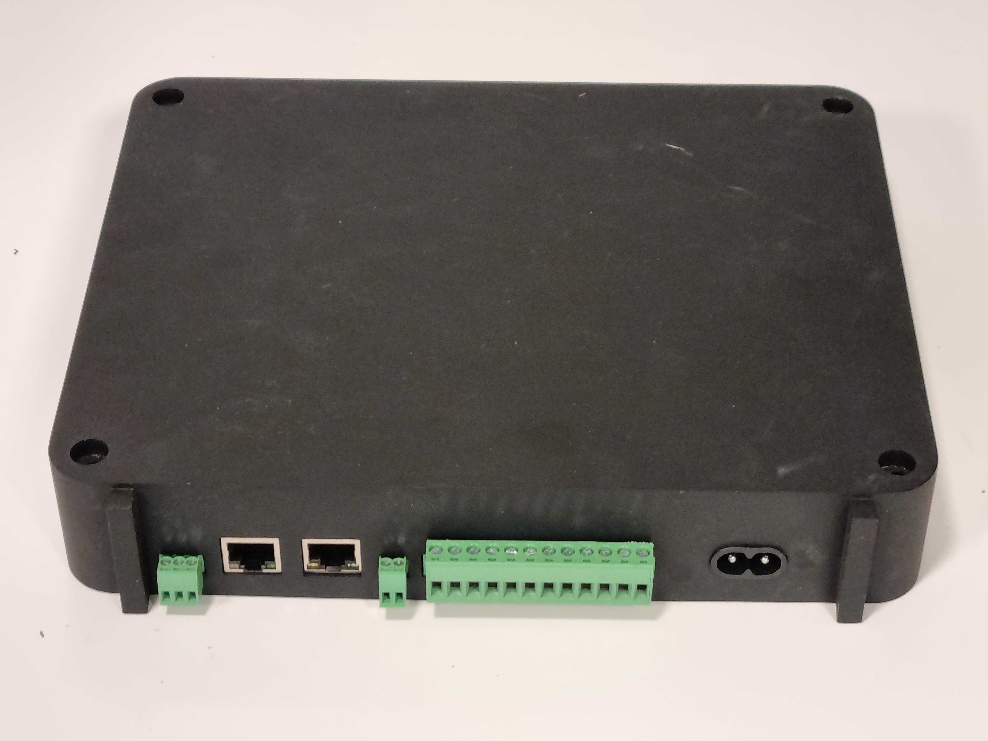
Click to zoom
Application Details
- Equipment Class
- JAB - Part 15 Class B Digital Device
- Date of Grant
- Jun 19, 2024
- Application Purpose
- Original Equipment
- Date of Application
- Jun 19, 2024
- Equipment Note
- Digital Intercom and access control system
- Company
- Defigo AS
- Country
- Norway
Documents & Files
Document Text
Text extracted from the exhibit documents filed with the FCC. Open a document above to read the original.
Users Manual
Defigo AS Org. nr. 913704665 Defigo Control unit Installation Manual Defigo AS Org. nr. 913704665 Package contents 1 – Defigo Control Unit 1 – Power Cable More information For more information go to https://www.getdefigo.com/partner/home Or contact us at [email protected] What you will need to install ● 1 Drill ● 4 screws appropriate for the type of wall you are mounting the Control unit on ● Minimum screw dimensions M4.5 x 60mm If installing Display together with the Control unit: ● 1 drill bit 16mm minimum for a cable with connectors ● 1 drill bit 10mm minimum for a cable without connectors ● A CAT-6 cable and RJ45 connectors, the cable, between the Display unit and the Defigo control unit, or for connecting the Display unit to a POE power source. Installation manual for Display unit is in a separate document. Prerequisite Defigo should only be installed by professional technicians with the proper training. Installers are expected to be able to use tools, crimp cables and other relevant activities to perform a technical installation. The Defigo control unit is meant for indoor installation only. Overview Thank you for choosing the Defigo access control system. The Control unit will control the doors when they are opened from the Defigo app. Defigo AS Org. nr. 913704665 IMPORTANT INFORMATION Read before you install NOTE: NEVER OPEN THE CONTROL UNIT CASE. THIS VOIDS THE WARRANTY OF THE UNIT AND COMPROMISE THE INTERNAL ENVIRONMENT OF THE ELECTRONICS. Installation preparations Before installation day you should provide the information from the QR code to Defigo by sending an email to [email protected]. Remember to add the address, entrance, and name of the door for the control unit. If installed together with a Display unit you need to provide the QR code for the correct Display as well. If connecting the Control unit to more than one door you need to provide which relay you will connect the door to. Doing this before the installation ensures that the system is prepared, that your user account is added to it for test purposes and that you have the necessary installation codes for the Defigo Displays. Choosing the position of the control unit The control unit can only be installed indoors in a dry environment. It should be placed out of reach for the public, preferably in a closed space or above a false ceiling. When choosing the right place for the control unit you need to assess the building layout. The control unit must be placed where 240/120V grid power is available. You also need to consider if it is needed to be connected to a Display unit or other devices like an elbow switch. The control unit should always be placed so that the connectors are facing down, so they are easily accessible for installation and service. What the Control unit can be connected to 12V and 24V DC door breeches. Connection to relays on access control systems, motor lock control devices, elevators, and other devices. Defigo Display unit. ATTENTION! Never use the 12VDC and 24VDC outputs on the control unit to power a door strike meant for AC only. In this case a separate power supply is required. The relays can still be used to control the signal. Defigo AS Org. nr. 913704665 Power and relay connections ● Maximum power delivered by the control unit: ○ 12V output 1.5 A ○ 24V output 1 A ● This is enough to power three normal door breeches at the same time. You will have to check the power consumption of each door lock to ensure that the control unit can deliver the necessary power to supply them at the same time. Other important factors you need to consider before installing the Defigo Display together with the Control unit: ● If the control unit powers a doorbell, the maximum CAT6 cable length between the control unit and the display is 50 meters. Defigo AS Org. nr. 913704665 INSTALLATION PROCEDURE Take the control unit out of the package. Make sure that it does not have any damage or scratches. Control unit connector layout: Defigo AS Org. nr. 913704665 STEP 1 Remove the connector cover by sliding it off vertically. Defigo AS Org. nr. 913704665 STEP 2 Find the place where you want the control unit installed. The control unit is mounted using four screws, one in each corner. NOTE: All screws are required. Make sure to use the screws appropriate for the type of wall/ceiling you are installing the control unit to. Defigo AS Org. nr. 913704665 STEP 3 Now that the control unit is safely mounted you are ready to connect the relays to door locks or other devices. You must choose whether you want to power the lock with current from the control unit, or if you just want to switch with a potential free signal. Follow step 3A or 3B depending on the options. ATTENTION! Never use the 12VDC and 24VDC outputs on the control unit to power a door strike meant for AC only. In this case a separate power supply is required. The relays can still be used to control the signal. STEP 3A: Door locks powered by the control unit Connect a jumper cable between 24 or 12V power and COM Connect GND to the negative pole of the lock Connect NO to the positive pole of the lock (For a lock setup that is NC use the NC connector instead of NO) Defigo AS Org. nr. 913704665 STEP 3B: Switch lock with potential free signal Connect COM and NO to a Button input on 3rd party door control unit or to the terminals on an elbow switch or other switches. Connect the first door to relay 1, second door to relay 2 and third door to relay 3. STEP 4 Connect the control unit to 240/120V power using the power cable provided in the package. STEP 5 Login to the Defigo app on your phone. From your Home Screen you will find the doors for the Control unit named as provided to Defigo before installation. Press the door icon for the door you want to test. NOTE! Please allow 5 minutes to pass from powering on the device before attempting to open the door using the app. For more information on using the app, see Defigo App user manual. Defigo AS Org. …
Text truncated - open the document above for the full version.
Attestation Statements
Covered Equipment Certification Attestation Letter 2/14/2023 Nemko North America, Inc. 303 River Road Ottawa K1V 1H2 Canada ATTN.: Reviewing Engineer FCC ID: 2A4C8DEFIGOG5C Defigo AS (“the applicant”) certifies that the equipment for which authorization is sought is not “covered” equipment prohibited from receiving an equipment authorization pursuant to section 2.903 of the FCC rules. Note: If the equipment for which the applicant seeks authorization is produced by any of the entities identified on the current Covered List, the applicant should include an explanation on why the equipment is not “covered” equipment. Defigo AS (“the applicant”) certifies that, as of the date of the filing of the application, the applicant is not identified on the Covered List as an entity producing “covered” equipment. Signed: Printed name: Marius L. Lillestøl Title: Director of Product Company Name: Defigo AS Date: 2/14/2023
Attestation Statements
U.S.AgentDesignationforServiceofProcess- CertificationAttestationLetter May6,2024 NemkoNorthAmerica,Inc. 303RiverRoad Ottawa K1V1H2 Canada ATTN.:ReviewingEngineer FCCID: 2A4C8DEFIGOG5C Persection2.911(d)(7)oftheFCCrules,DefigoAS(“theapplicant”)certifiesthattheequipment forwhichauthorizationissoughtisdesignatedtothefollowingU.S.Designatedagent*for serviceofprocess: FRN:0035152289 CompanyName:DefigoInc PhysicalU.S.CompanyAddress: 98CuttermillRoad,Ste466GreatNeckNY11021 Agentname:UmairAhmed AgentEmailAddress:[email protected] Theabovecontactpersonacceptstheobligationforserviceofprocess. Theapplicantacceptstomaintainanagentfornolessthanoneyearafterthegranteehas terminatedallmarketingandimportationortheconclusionofanyCommission-related proceedinginvolvingtheequipment. ApplicantSigned:DesignatedAgentSigned: (Required,ifdifferenttoApplicant): Signed: Signed: Printedname:MariusL.Lillestøl Printedname: UmairAhmed Title:DirectorofProductTitle:RVP,USSales CompanyName:DefigoASCompanyName:DefigoInc Date:4/11/2024Date:4/11/2024 * theapplicantmustdesignateacontactlocatedintheUnitedStatesforpurposesofactingasthe applicant’sagentforserviceofprocess,regardlessofwhethertheapplicantisadomesticorforeign entity.AnapplicantlocatedintheUnitedStatesmaydesignateitselfastheagentforserviceofprocess.
Cover Letter(s)
1/6/2023 Nemko North America, Inc. 303 River Road Ottawa, Ontario, Canada K1V 1H2 AUTHORITY TO ACT AS AGENT - FCC On our behalf, I appoint Nemko Scandinavia, to act as our agent in the preparation of this application for equipment certification. I certify that submitted documents properly describe the device or system for which equipment certification is sought. I also certify that each unit manufactured, imported or marketed, as defined in FCC regulations will have affixed to it a label identical to that submitted for approval with this application. In signing this letter, Applicant certifies that neither the applicant nor any party to the application is not subject to a denial of Federal benefits, that include FCC benefits, pursuant to Section 5301 of the Anti-Drug Abuse Act of 1988, 21 U.S.C. § 862 because of a conviction for possession or distribution of a controlled substance. See 47 CFR 1.2002(b) for the definition of a "party" for these purposes. For instances where our authorized agent signs the application for certification on our behalf, I acknowledge that all responsibility for complying with the terms and conditions for certification, as specified by Nemko North America Inc., still resides still resides with us. Sincerely, Printed name: Marius Lunder Lillestøl
Cover Letter(s)
1/6/2023 Nemko North America, Inc. 303 River Road Ottawa, Ontario, Canada K1V 1H2 REQUEST FOR CONFIDENTIALITY - FCC FCC ID: 2A4C8DEFIGOG5C Pursuant to Sections 0.457(d)(1)(ii) and 0.459 of the Commission’s Rules and FCC Guidance document 726920, we hereby request confidential treatment of information accompanying this application as outlined below: PERMANENT LONG-TERM CONFIDENTIALITY: Schematics Bill of Materials/Parts List Block Diagrams Theory of Operation When the device is marketed before the requested number of days listed above, the grantee will inform the TCB to release the Short-Term Confidentiality information withheld on the FCC equipment authorization website. The above information contains trade secrets and proprietary information not customarily released to the public. The public disclosure of this information might be harmful to the applicant and provide unjustified benefits to its competitors. The Applicant understands that pursuant to Rule 0.457(d)(1)(ii), disclosure of this Application and all accompanying materials will not be made before the date of the Grant for this Application. Sincerely, Signed: Printed name: Marius L. Lillestøl Title: Hardware Engineer
Test Report
Report No. 452909-03-R00 Template version: C Nemko Group Nemko Scandinavia AS, Instituttveien 6, 2027 Kjeller, Norway TEL +47 22 96 03 30 EMAIL [email protected] nemko.com/no Test Report Product Digital Intercom and Access Control System Name and address of the applicant Defigo AS Bogstadveien 27B 0355 Oslo, NORWAY Name and address of the manufacturer Defigo AS Bogstadveien 27B 0355 Oslo, NORWAY Model G5 Control Unit Rating Mains (120 V 60 Hz) Trademark Defigo Serial number B38SARA-R410M-02B-00_356726100931997_0215 Additional information LTE Tested according to FCC Part 15B Unintentional Radiators Industry Canada ICES-003, Issue 7 Information Technology Equipment (including Digital Apparatus) Order number 452909 Tested in period 2022-02-01 to 2022-02-03 Issue date 2022-04-06 Name and address of the testing laboratory Instituttveien 6 Kjeller, Norway www.nemko.com CAB Number: FCC: NO0001 ISED: NO0470 An accredited technical test executed under the Norwegian accreditation scheme Prepared by [Frode Sveinsen] Approved by [G.Suhanthakumar] This report shall not be reproduced except in full without the written approval of Nemko. Opinions and interpretations expressed within this report are not part of the current accreditation. This report was originally distributed electronically with digital signatures. For more information contact Nemko. TEST REPORT FCC Part 15B Report no.: 452909-02-R00 FCC ID: 2A4C8DEFIGOG5C Nemko Scandinavia AS Page 2 (12) Revision history Revision Date Comment Sign 00 2022-04-06 First edition FS THIS TEST REPORT APPLIES ONLY TO THE ITEM(S) AND CONFIGURATIONS TESTED. Deviations from, additions to, or exclusions from the test specifications are described in “Summary of Test Data”. Nemko Group authorizes the above named entity to reproduce this report provided it is reproduced in its entirety and for use by the entity’s employees only. Any reproduction of parts of this report requires approval in writing from Nemko Group. Any use that a third party makes of this report, or any reliance on or decisions to be made based on it, are the responsibility of such third parties. Nemko Group accepts no responsibility for damages suffered by any third party caused by decisions made or actions based on this report. TEST REPORT FCC Part 15B Report no.: 452909-02-R00 FCC ID: 2A4C8DEFIGOG5C Nemko Scandinavia AS Page 3 (12) CONTENTS 1 INFORMATION ......................................................................................................................... 4 1.1 Test Item ................................................................................................................................................... 4 1.2 Normal test condition ................................................................................................................................. 4 1.3 Test Engineer(s) ........................................................................................................................................ 4 1.4 EUT Operating Modes ............................................................................................................................... 4 1.5 Comments ................................................................................................................................................. 4 2 TEST REPORT SUMMARY ...................................................................................................... 5 2.1 General ..................................................................................................................................................... 5 2.2 Test Summary ........................................................................................................................................... 5 3 TEST RESULTS ........................................................................................................................ 6 3.1 Power Line Conducted Emissions ............................................................................................................. 6 3.2 Radiated Emissions, 30-1000 MHz ............................................................................................................ 7 3.3 Radiated Emissions, 1-10 GHz .................................................................................................................. 9 4 Measurement Uncertainty ..................................................................................................... 10 5 LIST OF TEST EQUIPMENT................................................................................................... 11 6 Test Setups ............................................................................................................................ 12 6.1 Power Line Conducted Emission ............................................................................................................. 12 6.2 Test Site Radiated Emission .................................................................................................................... 12 TEST REPORT FCC Part 15B Report no.: 452909-02-R00 FCC ID: 2A4C8DEFIGOG5C Nemko Scandinavia AS Page 4 (12) 1 INFORMATION 1.1 Test Item Name Defigo Model/version G5 Control Unit FCC ID 2A4C8DEFIGOG5C Serial number B38SARA-R410M-02B-00_356726100931997_0215 Hardware identity and/or version v9 Software identity and/or version V2.0.2 Power Supply Mains (120V 60 Hz) Conformance Class Class B Description of Test Item The EUT is a control unit for a digital intercom and access control system. The EUT also contains a certified LTE CAT-M1 Module from U-Blox. See information below. Certified Modules Manufacturer Model No Approval Numbers Supported Frequency Bands Uplink Freq Ublox SARA-R410M-52B LTE CAT-M1 FCC ID: XPY2AGQN4NNN IC: 8595A-2AGQN4NNN Band 02 Band 04 Band 05 Band 12 Band 13 1850.0 – 1910.0 1710.0 – 1755.0 824.0 – 849.0 699.0 – 716.0 777.0 – 787.0 1.2 Normal test condition Temperature: 20 - 24 ° C Relative humidity: 20 - 50 % Normal test voltage: 12…
Text truncated - open the document above for the full version.
Test Setup Photos
TEST SET-UP PHOTOS Project no.: 452909 FCC ID: 2A4C8DEFIGOG5C IC: 28180-DEFIGOG5C Page 1 (1) Nemko Scandinavia Radiated Emissions Below 30 MHz Radiated Emissions 30 – 1000 MHz Power-Line Conducted Emissions
Contact Information
Applicant
Marius Lillestol
Test Firm
Nemko Scandinavia ASFrode Sveinsen
[email protected]+4796905548
Technical Specifications
| # | Rule Parts | Frequency Range | Power Output |
|---|---|---|---|
| 1 | 15B | - | - |