2A4DDLPXAEJTwo-way Radio
Shine Flex US LLC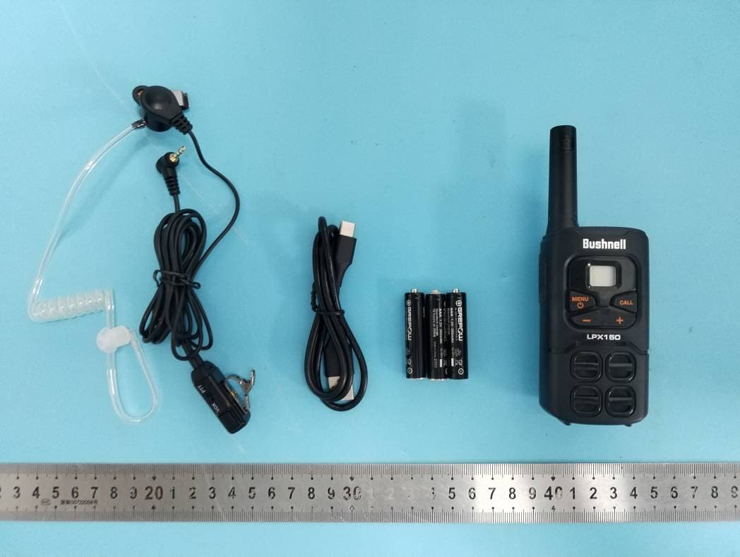
Click to zoom
Application Details
- Equipment Class
- FRF - Part 95 Family Radio Face Held Transmitter
- Date of Grant
- Jan 18, 2023
- Application Purpose
- Original Equipment
- Date of Application
- Jan 18, 2023
- Equipment Note
- Two-way Radio
- Frequency Range
- 467.56250000 - 467.71250000
- Company
- Shine Flex US LLC
- Country
- United States
Documents & Files
Document Text
Text extracted from the exhibit documents filed with the FCC. Open a document above to read the original.
Users Manual
IMPORTANT NOTICE: Changes o『modific _ ation _ sto_this unit not exp『esslyappr _ oved by the party responsible fo『compliance could void the user's authority to operate the equipment. 而sdevice complies with Part 15 of the FCC Rules. Operation is subject to the following two conditions: 1) This device may not cause harmful interference, and 2) this device must accept any interfe『ence 『eceived,includinginterference that may cause undesired operation. FCC Wamings: Replacement or substitution of transistors, regular diodes or other parts of a unique nature, with parts other than those recommended by Bushnell may cause a violation of the technical regulations of part 95 of the FCC rules, or violation of type acceptance requirements of part 2 of the rules. 伽sequipment has been tested and found to comply with the limits for a Class B digital device, pursuant to Part 15 of the FCC Rules. These limlts are designed to provide reasonable protection against harmful interference in a residential installation而sequipment generates, uses and can radiate radio frequency energy and, tt not installed and used in accordance with the instructions, may cause hannful lnterfe『enceto radio communlca廿ons. However, the『eis no guarantee that interference will not occur in a particula『installa廿on.If this equipment does cause hannful interference to radio or television reception, which can be detennined by tuming the equipment off and on, the user is encouraged to try to correct the interfe『enceby one o『mo『eof the following measu『es • Reo『lentor relocate the receiving antenna. • Increase the separa廿onbetween the equipment and『eceive『. • Connect the equipment Into an outlet on a circuit different from that to which the receiver Is connected. • Consult the dealer o『anexperienced radiofTV technician fo『help A Safety Information for Radios Your wlreless handheld portable transceiver contains a low powe『 transmitter. When the talk button I s pushed, It sends out radio frequency (RF) signals. The device Is authorized to operate at a duty factOJ'not切exceed 50%. In August 1996, the Federal Communications Commissions (FCC) adopted RF exposure guidelines with safety levels for handheld wireless devices lmportsnt FCC RF Exposure Requi『ements: For body-wom operation, this 『adio has been tested and meets the FCC RF exposure guidelines when used with Bushnell accessories supplied or designated for this product. Use of other accessories may not ensure compliance with FCC RF exposure guidelines. Use only t he supplied antenna. Unauthorized antennas, mod廿ications or attachments could damage the transmitter and may violate FCC regulations Normal Position Hold the transmitter approximately (25mm) from your face and speak in a normal voice, with the antenna pointed up and away. ISEDC Warning 而s device complies with Innovation, Science, and Economic Oevelopment Canada licence-exempt RSS standard(s). Operation is subject切the following two conditions: (1) this device may not cause interference, and (2) this device must accept any interference, including interference that may cause undesired operation of the device. ISEDC Radiation Exposure Statement Forboclywom叩eration,this model device has been tested and meets the ISED RF exposure guidelines when used with an accessory designated for this product or when used with an accessory that Contains no metal and that positions of the face up minimum distance is 25 mm. Any Changes OJ'modifications not expressly approved by the party responsible for compliance could void the user's authority切operatethe equipment 14 Your wireless handheld portable transceiver contains a low powe「transmitter.When the talk button Is pushed, It sends out radio frequency (RF) signals. The device Is authorized to 咖ratea t a duty factor not t o exceed 50% 心,汪正,和I,三屾 Lim忱edLifetime Warranty on Radio Shine Flex warrants to the original consumer purchaser only that this product and the component parts thereof, will be free from defects in workmanship and materials During this period, Shine Flex will, repair or replace, at its sole option and disc「etion, this product or any defective parts. Shine Flex's liability hereunder shall be I皿tedto repair or replacement of the defective part or parts, and such correction shall constitute a fulfillment of all of Shine Flex's warranties hereunder. This limtted warranty does not apply to accessories and consumables and is only valid fo「theoriginal consumer pu『chaserin I,而tedjurisdictions and is not transferrable. This 血tedwarranty will automatically terminate prior to expiration if this product is sold or otherwise transferred to another party. The product must be purchased from Shine Flex or an authorized dealer or the warranty is void. This limited warranty is valid only for products purchased and utilized in specific jurisd昢ons.Please visit our webstte at www.shineflexglobal.com for a list of jurisd昢onswherein this limited warranty is valid This limtted warranty does not cover damage due to misuse, abuse, negligence, acts of God, accident, commercial use or modification of, or to any part of this product. This warranty does not cover damage due to improper operation, maintenance or installation; ordinary wear and tear; or attempted alterations or repairs by anyone other than Shine Flex or someone authorized by Shine Flex to do wa『rantywork. Any unauthorized alterations or repairs will void this warranty. This limited warranty does not cover product sold AS IS or WITH ALL FAULTS. This limited warranty is invalid � the factory applied serial number o『datestamp has been altered, defaced or removed from this product. This limited warranty does not cover product pu『chasedor utilized in a jurisd昢onnot covered. The procedure for obta皿ngservice and support, and the applicability of this warranty, will vary depending on the country or jurisdiction in which you purchase and utilize the product. For details on obtaining product service, support and other warranty information please v吼www.shlnellex…
Text truncated - open the document above for the full version.
External Photos
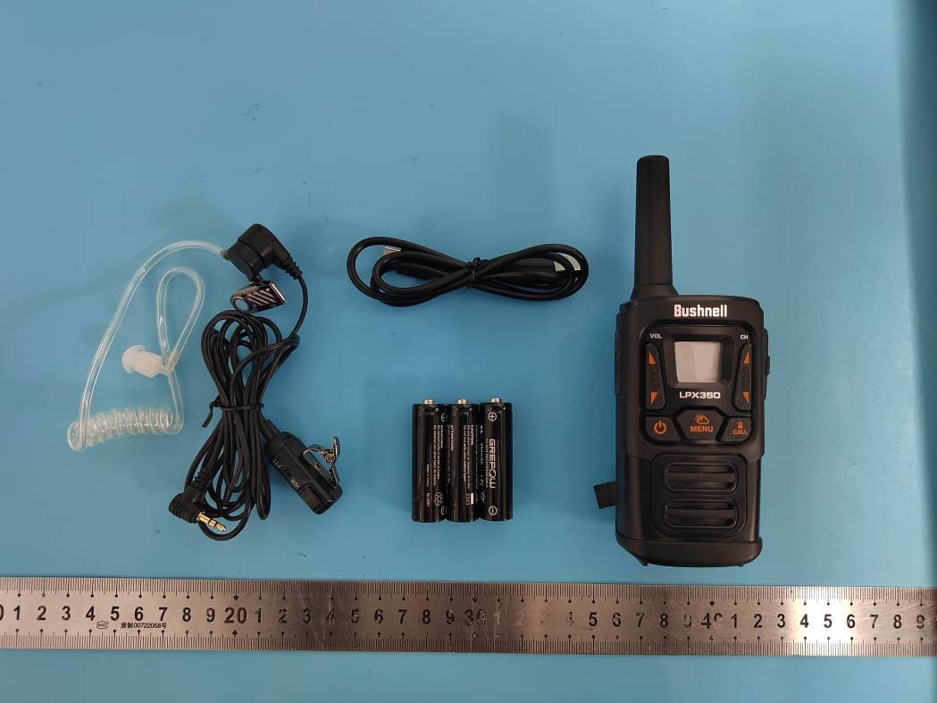
Shenzhen Accurate Technology Co., Ltd. FCC ID: 2A4DDLPXAEJ External Photos Page 1 of 4 External Photos Shenzhen Accurate Technology Co., Ltd. FCC ID: 2A4DDLPXAEJ External Photos Page 2 of 4 Shenzhen Accurate Technology Co., Ltd. FCC ID: 2A4DDLPXAEJ External Photos Page 3 of 4 Shenzhen Accurate Technology Co., Ltd. FCC ID: 2A4DDLPXAEJ External Photos Page 4 of 4
ID Label/Location Info
Shenzhen Accurate Technology Co., Ltd. Project No.: RA221124-56533E-RF LABEL AND LOCATION Page 1 of 1 FCC ID Label FCC ID Label Location Information The label shown shall be permanently affixed at a conspicuous location on the device and be readily visible to the user at the time purchase (Labeling requirements per 2.925)
Internal Photos
Shenzhen Accurate Technology Co., Ltd. FCC ID: 2A4DDLPXFEJ Internal Photos Page 1 of 4 Internal photos Shenzhen Accurate Technology Co., Ltd. FCC ID: 2A4DDLPXFEJ Internal Photos Page 2 of 4 Shenzhen Accurate Technology Co., Ltd. FCC ID: 2A4DDLPXFEJ Internal Photos Page 3 of 4 ANT Shenzhen Accurate Technology Co., Ltd. FCC ID: 2A4DDLPXFEJ Internal Photos Page 4 of 4
RF Exposure Info
SAR TEST REPORT Applicant: Shine Flex US LLC Address: 1259 Knollwood Road Deerfield IL 60015 USA FCC ID: 2A4DDLPXAEJ Product Name: Two-way Radio Model Numbers: LPX150 Standard(s): 47 CFR Part 2(2.1093) The above equipment has been tested and found compliant with the requirement of the relative standards by China Certification ICT Co., Ltd (Dongguan) Report Number: CR221156534-20A Date Of Issue: 2022-12-09 Reviewed By: Karl Gong Title: SAR Engineer Test Laboratory: China Certification ICT Co., Ltd (Dongguan) No. 113, Pingkang Road, Dalang Town, Dongguan, Guangdong, China Tel: +86-769-82016888 China Certification ICT Co., Ltd (Dongguan) Report No.:CR221156534-20A Page 2 of 53 SAR TEST RESULTS SUMMARY Operation Frequency Bands Highest Reported 1g SAR (W/kg) Limits (W/kg) Head Face Up (Gap 25mm) Body-Worn (Gap 0mm) PTT(462.5500-467.7125MHz) 0.180.31.6 Maximum Simultaneous Transmission SAR Items Head Face Up (Gap 25mm) Body-Worn (Gap 0mm) Limits Sum SAR(W/kg) N/A N/A 1.6 SPLSRN/AN/A0.04 EUT Received Date: 2022/11/06 Tested Date: 2022/11/08 Tested Result: Pass China Certification ICT Co., Ltd (Dongguan) Report No.:CR221156534-20A Page 3 of 53 Test Facility The Test site used by China Certification ICT Co., Ltd (Dongguan) to collect test data is located on the No. 113, Pingkang Road, Dalang Town, Dongguan, Guangdong, China. The lab has been recognized as the FCC accredited lab under the KDB 974614 D01 and is listed in the FCC Public Access Link (PAL) database, FCC Registration No. : 442868, the FCC Designation No. : CN1314. The lab has been recognized by Innovation, Science and Economic Development Canada to test to Canadian radio equipment requirements, the CAB identifier: CN0123. Declarations China Certification ICT Co., Ltd (Dongguan) is not responsible for the authenticity of any test data provided by the applicant. Data included from the applicant that may affect test results are marked with a triangle symbol “▲”. Customer model name, addresses, names, trademarks etc. are not considered data. Unless otherwise stated the results shown in this test report refer only to the sample(s) tested. This report cannot be reproduced except in full, without prior written approval of the Company. This report is valid only with a valid digital signature. The digital signature may be available only under the Adobe software above version 7.0. This report may contain data that are not covered by the accreditation scope and shall be marked with an asterisk “★”. China Certification ICT Co., Ltd (Dongguan) Report No.:CR221156534-20A Page 4 of 53 CONTENTS SAR TEST RESULTS SUMMARY .............................................................................................. 2 TEST FACILITY .......................................................................................................................................... 3 DECLARATIONS .......................................................................................................................................... 3 1. GENERAL INFORMATION .................................................................................................... 6 1.1 PRODUCT DESCRIPTION FOR EQUIPMENT UNDER TEST (EUT) ....................................................... 6 1.2 TEST SPECIFICATION, METHODS AND PROCEDURES ........................................................................ 7 1.3 SAR LIMTS ........................................................................................................................................... 8 2. SAR MEASUREMENT SYSTEM ............................................................................................ 9 3. EQUIPMENT LIST AND CALIBRATION .......................................................................... 16 3.1 EQUIPMENTS LIST & CALIBRATION INFORMATION ....................................................................... 16 4. SAR MEASUREMENT SYSTEM VERIFICATION ........................................................... 17 4.1 LIQUID VERIFICATION ...................................................................................................................... 17 4.2 SYSTEM ACCURACY VERIFICATION ................................................................................................. 18 4.3 SAR SYSTEM VALIDATION DATA ............................................................................................. 19 5. EUT TEST STRATEGY AND METHODOLOGY .............................................................. 20 5.1 TEST POSITIONS FOR DEVICE OPERATING NEXT TO A PERSON’S EAR ......................................... 20 5.2 CHEEK/TOUCH POSITION .................................................................................................................. 21 5.3 EAR/TILT POSITION ........................................................................................................................... 21 5.4 TEST POSITIONS FOR BODY-WORN AND OTHER CONFIGURATIONS ............................................... 22 5.5 TEST DISTANCE FOR SAR EVALUATION .......................................................................................... 23 5.6 SAR EVALUATION PROCEDURE ....................................................................................................... 24 6. RADIATED OUTPUT POWER MEASUREMENT ............................................................ 25 6.1 TEST PROCEDURE .............................................................................................................................. 25 6.2 MAXIMUM TARGET OUTPUT POWER ............................................................................................... 25 6.3 TEST RESULTS: .................................................................................................................................. 25 7. SAR MEASUREMENT RESULTS ........................................................................................ 27 7.1 SAR TEST DATA .............................................................…
Text truncated - open the document above for the full version.
Test Report
Note: This report may contain data that are not covere ★ d by the A2LA accreditation and are marked with an asterisk “ ”. Shenzhen Accurate Technology Co., Ltd. is not responsible for the authenticity of any test data provided by the applicant. Data included from the applicant that may affect test results are marked with an asterisk ’*’. Customer model name, addresses, names, trademarks etc. are not considered data. This report cannot be reproduced except in full, without prior written approval of the Company. Unless otherwise stated the results shown in this test report refer only to the sample(s) tested. This report is valid only with a valid digital signature. The digital signature may be available only under the Adobe software above version 7.0. Shenzhen Accurate Technology Co., Ltd. 1/F., Building A, Changyuan New Material Port, Science & Industry Park, Nanshan District, Shenzhen, Guangdong, P.R. China Tel: +86 755-26503290 Fax: +86 755-26503396 Web: www.atc-lab.com Version 26: 2021-11-09 Page 1 of 30 FCC- RF TEST REPORT Applicant Name : Shine Flex US LLC Address : 1259 Knollwood Road Deerfield IL 60015 USA Report Number : RA221124-56533E-RF-00 FCC ID: 2A4DDLPXAEJ Test Standard (s) FCC PART 95 Sample Description Product Type: Two-way Radio Model No.: LPX150 Multiple Model(s) No.: N/A Trade Mark: Bushnell Date Received: 2022/11/24 Report Date: 2022/12/19 Test Result: Pass* * In the configuration tested, the EUT complied with the standards above. Prepared and Checked By: Approved By: Andy Yu Candy Li EMC Engineer EMC Engineer Shenzhen Accurate Technology Co., Ltd. Report No.: RA221124-56533E-RF-00 Version 26: 2021-11-09 Page 2 of 30 FCC- RF TABLE OF CONTENTS GENERAL INFORMATION ....................................................................................................................................... 3 PRODUCT DESCRIPTION FOR EQUIPMENT UNDER TEST (EUT) .................................................................................... 3 OBJECTIVE ................................................................................................................................................................... 3 TEST METHODOLOGY .................................................................................................................................................. 3 MEASUREMENT UNCERTAINTY .................................................................................................................................... 4 TEST FACILITY ............................................................................................................................................................. 4 SYSTEM TEST CONFIGURATION .......................................................................................................................... 5 DESCRIPTION OF TEST CONFIGURATION ...................................................................................................................... 5 EQUIPMENT MODIFICATIONS ....................................................................................................................................... 5 SUPPORT EQUIPMENT LIST AND DETAILS .................................................................................................................... 5 EXTERNAL I/O CABLE .................................................................................................................................................. 5 BLOCK DIAGRAM OF TEST SETUP ................................................................................................................................ 6 SUMMARY OF TEST RESULTS ............................................................................................................................... 7 TEST EQUIPMENT LIST ........................................................................................................................................... 8 §2.1093 - RF EXPOSURE INFORMATION .............................................................................................................. 9 APPLICABLE STANDARD .............................................................................................................................................. 9 TEST RESULT ............................................................................................................................................................... 9 FCC §2.1046 & §95.567 - RF OUTPUT POWER ..................................................................................................... 10 APPLICABLE STANDARD ............................................................................................................................................ 10 TEST PROCEDURE ...................................................................................................................................................... 10 TEST DATA ................................................................................................................................................................ 10 FCC §2.1047 & §95.575 - MODULATION CHARACTERISTIC .......................................................................... 11 APPLICABLE STANDARD ............................................................................................................................................ 11 TEST PROCEDURE ...................................................................................................................................................... 11 TEST DATA ................................................................................................................................................................ 11 FCC §2.1049 & §95.573 & §95.579 - AUTHOURIZED BANDWIDTH AND EMISSION MASK ...................... 22 APPLICABLE STANDARD ............................................................................................................................................ 22 TEST PROCEDURE ......................…
Text truncated - open the document above for the full version.
Test Setup Photos
Shenzhen Accurate Technology Co., Ltd. Project No.: RA221124-56533E-RF Test Photos Page 1 of 1 Photo of Radiated Emission Measurement (Below 1G) Photo of Radiated Emission Measurement (Above 1G)
Contact Information
Applicant
Greg Reichman(Manager)
Test Firm
Shenzhen Accurate Technology Co., Ltd.Lisa Zhang
[email protected]+86-755-26503290
Technical Specifications
| # | Rule Parts | Frequency Range | Power Output | Emission | Tolerance |
|---|---|---|---|---|---|
| 2 | 95B | 467.5625 MHz - 467.7125 MHz | 400.00 mW | 11K0F3E | 2.5 ppm |
Other Applications from Shine Flex US LLC
2A4DDLPXCEJ
Feb 16, 2023Two-way Radio
Equipment Class
FRF - Part 95 Family Radio Face Held Transmitter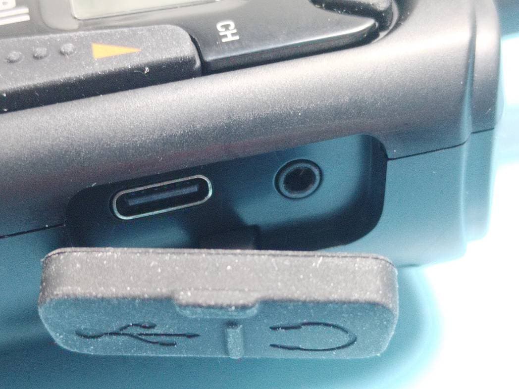
2A4DDLPXEEJ
Feb 14, 2023Two-way Radio
Equipment Class
FRF - Part 95 Family Radio Face Held Transmitter