2A4G3-NJ81Keydous mechanical keyboard
Zhuhai Qiannuo Technology Co,.Ltd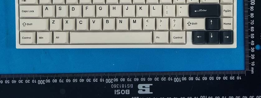
Click to zoom
Application Details
- Equipment Class
- DSS - Part 15 Spread Spectrum Transmitter
- Date of Grant
- Dec 18, 2022
- Application Purpose
- Original Equipment
- Date of Application
- Dec 18, 2022
- Equipment Note
- Keydous mechanical keyboard
- Frequency Range
- 2402.00000000 - 2480.00000000
- Country
- China
Documents & Files
Document Text
Text extracted from the exhibit documents filed with the FCC. Open a document above to read the original.
Users Manual
User Manual -Start a New Journey of Thock and Clack- FCC Requirement Any changes or modifications not expressly approved by the party responsible for compliance could void the user’s authority to operate the equipment. This device complies with Part 15 of the FCC Rules. Operation is subject to the following two conditions: (1) this device may not cause harmful interference, and (2) this device must accept any interference received, including interference that may cause undesired operation. Note: This equipment has been tested and found to comply with the limits for a Class B digital device, pursuant to Part 15 of the FCC Rules. These limits are designed to provide reasonable protection against harmful interference in a residential installation. This equipment generates, uses, and can radiate radio frequency energy, and if not installed and used in accordance with the instructions, may cause harmful interference to radio communications. However, there is no guarantee that interference will not occur in a particular installation. If this equipment does cause harmful interference to radio or television reception, which can be determined by turning the equipment off and on, the user is encouraged to try to correct the interference by one or more of the following measures: – Reorient or relocate the receiving antenna. – Increase the separation between the equipment and receiver. – Connect the equipment into an outlet on a circuit different from that to which the receiver is connected. – Consult the dealer or an experienced radio/TV technician for help. Company Name: Zhuhai Qiannuo Tech. Co.,Ltd Address: Room 906-2, Floor 9, Building 2, No.88 Xiangshan Road, Tangjia Town, High Tech Zone, Zhuhai, China Email: [email protected] | [email protected] Official Website: www.keydous.com Notice ① WiFi will interfere the Bluetooth signal. Make sure the keyboard far away from the WiFi devices if the Bluetooth gets delay evidently. ② DO NOT swap the switches with hard force. Or the socket even the entire PCB may get DAMAGED. ③ DO NOT put the keyboard in the high-temperature, high-pressure or sun direct places due to the built-in battery. ④ DO NOT charge the keyboard with charging current that OVER 5V 1A or the PCB will be DAMAGED. It is better to use the original cable to charge. FKeydous mechanical keyboard Default RGB Backlight ① FN+ESC = Exit the lighting effects ② FN+Enter = Change the Backlight color. ③ FN+Backspace=Turn lights on/off [Entering Power Save Mode when OFF] ④ FN+ | \= Change the light effects. ⑤ FN+ ↑ / ↓ = Increase / decrease light brightness . ⑥ FN+ ← / → = Decrease / Increase light speed. ⑦ FN+Tab= Adjust the sleep time of lights. Flashes once for entering sleep mode after 2 mins and twice for 30 mins. ⑧ Cannot assign light effect in CAPS Key. Color adjusting only by clicking FN+Caps. Default FN Key Combinations FN+1/2/3= Switch Bluetooth devices Fn+5= Switch to wired mode FN+ Home = End FN+I=Insert FN+ ? = Calculator FN+10 = Mute FN+ += Volume UP FN+ - =Volume Down FN+L= Browser FN+ Right Shift= My computer FN+Win= Lock / Unlock the WIN key FN+P=Print Fn+~ = Switch to customized lighting[FN + Ees to exit] ESC + Left CTRL + F12 + Right Arrow = Resume the Keyboard to factory setting How to Operate the Screen FN+Delete= Enter/Exit the custom screen interface FN+Right Ctrl= open/close screen FN+PgUp= Change the font color FN+PgDn= Change the background color MAC Mode ① Press FN+M for 2 seconds, White Light of CAPS flashes Once / Twice to Exit / Enter Mac Mode. Left top corner of the Screen displays the current mode. ② Position Changes -Left Alt exchanges with WIN. -Right ALT becomes WIN -Right CTRL becomes ALT ③ Short press FN+F to Switch multimedia / standard key in F zone. Triple Connecting Modes Light will fast flash when pairing devices ① Bluetooth Mode Press FN+1/2/3 for 3 seconds and then select the BT 5.0KB [Win7 is BT 3.0KB] to pair the devices.Shortly press FN+1/2/3 to switch devices. ② Shortly press FN+4 to enter 2.4G wireless mode Note: Please make keyboard close to 2.4G receiver for the first use. ③ Shortly press FN+5 to enter wired mode Note: Automatically turned into wired mode when plug in the cable. Dongle FCC ID:2A9BL-TK65D FCC Radiation Exposure Statement This equipment complies with FCC radiation exposure limits set forth for an uncontrolled environment . This transmitter must not be co-located or operating in conjunction with any other antenna or transmitter.
Cover Letter(s)
QA-FR-170-B Zhuhai Qiannuo Technology Co,.Ltd Add: floor9,building 2,No.88,Xiangshan Road, Tangjiawan Town, high tech Zone, Zhuhai,China Tel: 86-18675582602 Fax: 0755-28561031 Email:[email protected] FCC Authorization Date: 2022-12-08 FEDERAL COMMUNICATIONS COMMISSION Authorization and Evaluation Division 7435 Oakland Mills Road Columbia, MD 21046 Subject: Agent Authorization To whom it may concern: We , Zhuhai Qiannuo Technology Co,.Ltd , Hereby authorizes China Certification ICT Co., Ltd (Dongguan) to act on its behalf in all matters relating to application for Equipment authorization, including the signing of all documents relating to these matters. All acts carried out by China Certification ICT Co., Ltd (Dongguan) on our behalf shall have the same effect as our own action. We, the undersigned, hereby certify that we are not subject to a denial of federal benefits, that includes FCC benefits, pursuant to Section 5301 of the Anti-Drug Abuse Act of 1988, 21 U.S.C. 862. This authorization is valid until further written notice from the applicant. Sincerely Yours, Client’s signature Printed Name: wenshan huang Title: manager
Cover Letter(s)
QA-FR-171-A Zhuhai Qiannuo Technology Co,.Ltd Add: floor9,building 2,No.88,Xiangshan Road, Tangjiawan Town, high tech Zone, Zhuhai,China Tel: 86-18675582602 Fax: 0755-28561031 Email:[email protected] FCC Confidential Authorization Date: 2022-12-08 FEDERAL COMMUNICATIONS COMMISSION Authorization and Evaluation Division 7435 Oakland Mills Road Columbia, MD 21046 Subject: Confidentiality Request regarding application for certification of FCC ID:2A4G3-NJ81 In accordance with Sections 0.457 and 0.459 of the Commission’s Rules, (Zhuhai Qiannuo Technology Co,.Ltd) hereby requests long-term confidential treatment of information accompanying this application as outlined below: Block Diagram Schematics Operation Description The above materials contain proprietary and confidential information not customarily released to the public. The public disclosure of these materials provides unjustified benefits to its competitors in the market. Sincerely, Signature: Printed Name: wenshan huang Title: manager
External Photos
EXHIBIT B - EUT EXTERNAL PHOTOGRAPHS PORT
ID Label/Location Info
® www.keydous.com MADE IN CHINA Max charging input:5V1A Keydous NJ81 MODEL:NJ81 SN:0000001 FCC ID:2A4G3-NJ81
Internal Photos
EXHIBIT C - EUT INTERNAL PHOTOGRAPHS Antenna
RF Exposure Info
China Certification ICT Co., Ltd (Dongguan) Report No.: CR221150831-00B Page 53 of 53 5. RF EXPOSURE EVALUATION 5.1 Applicable Standard According to§15.247(i) and §1.1310, systems operating under the provisions of this section shall be operated in a manner that ensure that the public is not exposed to radio frequency energy level in excess of the Commission’s guideline. According to KDB447498 D01 General RF Exposure Guidance v06: The 1-g and 10-g SAR test exclusion thresholds for 100 MHz to 6 GHz at test separation distances ≤ 50 mm are determined by: [(max. power of channel, including tune-up tolerance, mW)/(min. test separation distance, mm)] ꞏ [√f(GHz)] ≤ 3.0 for 1-g SAR and ≤ 7.5 for 10-g extremity SAR, where • f(GHz) is the RF channel transmit frequency in GHz • Power and distance are rounded to the nearest mW and mm before calculation • The result is rounded to one decimal place for comparison • 3.0 and 7.5 are referred to as the numeric thresholds in the step 2 below The test exclusions are applicable only when the minimum test separation distance is ≤ 50 mm and for transmission frequencies between 100 MHz and 6 GHz. When the minimum test separation distance is < 5 mm, a distance of 5 mm according to 5) in section 4.1 is applied to determine SAR test exclusion. 5.2 Measurement Result For BT The max conducted power including tune-up tolerance is 7.0 dBm (5.01 mW). [(max. power of channel, mW)/(min. test separation distance, mm)][√f(GHz)] =5.01/5*(√2.480) = 1.58< 3.0 Result: Compliance. The stand-alone SAR evaluation is not necessary ===== END OF REPORT =====
Test Report
TEST REPORT Applicant: Zhuhai Qiannuo Technology Co,.Ltd Address: floor9, building 2, No.88, Xiangshan Road, Tangjiawan Town, high tech Zone, Zhuhai, China FCC ID: 2A4G3-NJ81 Product Name: Keydous mechanical keyboard Standard(s): 47 CFR Part 15, Subpart C(15.247) ANSI C63.10-2013 KDB 558074 D01 15.247 Meas Guidance v05r02 The above equipment has been tested and found compliant with the requirement of the relative standards by China Certification ICT Co., Ltd (Dongguan) Report Number: CR221150831-00B Date Of Issue: 2022-12-14 Reviewed By: Sun Zhong Title: Manager Test Laboratory: China Certification ICT Co., Ltd (Dongguan) No. 113, Pingkang Road, Dalang Town, Dongguan, Guangdong, China Tel: +86-769-82016888 China Certification ICT Co., Ltd (Dongguan) Report No.: CR221150831-00B Page 2 of 53 Test Facility The Test site used by China Certification ICT Co., Ltd (Dongguan) to collect test data is located on the No. 113, Pingkang Road, Dalang Town, Dongguan, Guangdong, China. The lab has been recognized as the FCC accredited lab under the KDB 974614 D01 and is listed in the FCC Public Access Link (PAL) database, FCC Registration No. : 442868, the FCC Designation No. : CN1314. The lab has been recognized by Innovation, Science and Economic Development Canada to test to Canadian radio equipment requirements, the CAB identifier: CN0123. Declarations China Certification ICT Co., Ltd (Dongguan) is not responsible for the authenticity of any test data provided by the applicant. Data included from the applicant that may affect test results are marked with a triangle symbol “▲”. Customer model name, addresses, names, trademarks etc. are not considered data. Unless otherwise stated the results shown in this test report refer only to the sample(s) tested. This report cannot be reproduced except in full, without prior written approval of the Company. This report is valid only with a valid digital signature. The digital signature may be available only under the Adobe software above version 7.0. This report may contain data that are not covered by the accreditation scope and shall be marked with an asterisk “★”. China Certification ICT Co., Ltd (Dongguan) Report No.: CR221150831-00B Page 3 of 53 CONTENTS T EST FACILITY .......................................................................................................................................... 2 DECLARATIONS .......................................................................................................................................... 2 1. GENERAL INFORMATION .................................................................................................... 5 1.1 PRODUCT DESCRIPTION FOR EQUIPMENT UNDER TEST (EUT) ....................................................... 5 1.2 DESCRIPTION OF TEST CONFIGURATION ........................................................................................... 6 1.2.2 Support Equipment List and Details .............................................................................................................. 6 1.2.3 Support Cable List and Details ...................................................................................................................... 6 1.2.4 Block Diagram of Test Setup ......................................................................................................................... 7 1.3 MEASUREMENT UNCERTAINTY .......................................................................................................... 8 2. SUMMARY OF TEST RESULTS ............................................................................................ 9 3. REQUIREMENTS AND TEST PROCEDURES .................................................................. 10 3.1 AC LINE CONDUCTED EMISSIONS .................................................................................................... 10 3.1.1 Applicable Standard ..................................................................................................................................... 10 3.1.2 EUT Setup.................................................................................................................................................... 11 3.1.3 EMI Test Receiver Setup ............................................................................................................................. 11 3.1.4 Test Procedure ............................................................................................................................................. 12 3.1.5 Corrected Amplitude & Margin Calculation ................................................................................................ 12 3.2 RADIATION SPURIOUS EMISSIONS .................................................................................................... 13 3.2.1 Applicable Standard ..................................................................................................................................... 13 3.2.2 EUT Setup.................................................................................................................................................... 13 3.2.3 EMI Test Receiver & Spectrum Analyzer Setup ......................................................................................... 14 3.2.4 Test Procedure ............................................................................................................................................. 14 3.2.5 Corrected Amplitude & Margin Calculation ................................................................................................ 14 3.3 20 DB BANDWIDTH ............................................................................................................................. 1 5 3.3.1 Applicable Standard ..................................................................................................................................... 15 3.3.2 EUT Setup......................................................................…
Text truncated - open the document above for the full version.
Test Report
FreqEffiEffiGainGainMaxMinAttenut Attenut (MHz)(%%)(dB)(dBi)(dBd)(dB)(dB)HorVer 240041.98-3.771.33-0.821.33 -14.0653.2852.56 241042.92-3.671.38-0.771.38 -15.2853.3452.58 242044.03-3.561.63-0.521.63 -15.6353.4552.63 243045.24-3.441.71-0.441.71 -14.8553.3352.73 244045.55-3.411.71-0.441.71 -12.4253.3752.78 245048.27-3.161.82-0.331.82-9.6453.4653.02 246046.38-3.341.35-0.81.35-7.8653.4752.9 247046.86-3.291.08-1.071.08-8.4853.5452.93 248047.41-3.240.8-1.350.8-9.853.5452.79 249048.86-3.110.64-1.510.64 -11.5953.5452.88 250047.54-3.230.69-1.460.69 -14.1953.5252.85 Passive Test For 2.4G Manufacture:Zhuhai Qiannuo Technology Co,.Ltd floor9, building 2, No.88, Xiangshan Road, Tangjiawan Town, high tech Zone, Zhuhai, China Antenna model:PCB-NJ
Test Setup Photos
EXHIBIT D - TEST SETUP PHOTOGRAPHS Conducted Emissions Front View Conducted Emissions Side View Radiated Emission Below 1GHz View Radiated Emission Above 1GHz View
Contact Information
Applicant
wenshan huang
Test Firm
CHINA CERTIFICATION ICT CO., LTD (DONGGUAN)Tanie Ou
[email protected]0086 0769 86858888
Technical Specifications
| # | Rule Parts | Frequency Range | Power Output |
|---|---|---|---|
| 1 | 15C | 2.40 GHz - 2.48 GHz | 4.00 mW |
Other Applications from Zhuhai Qiannuo Technology Co,.Ltd
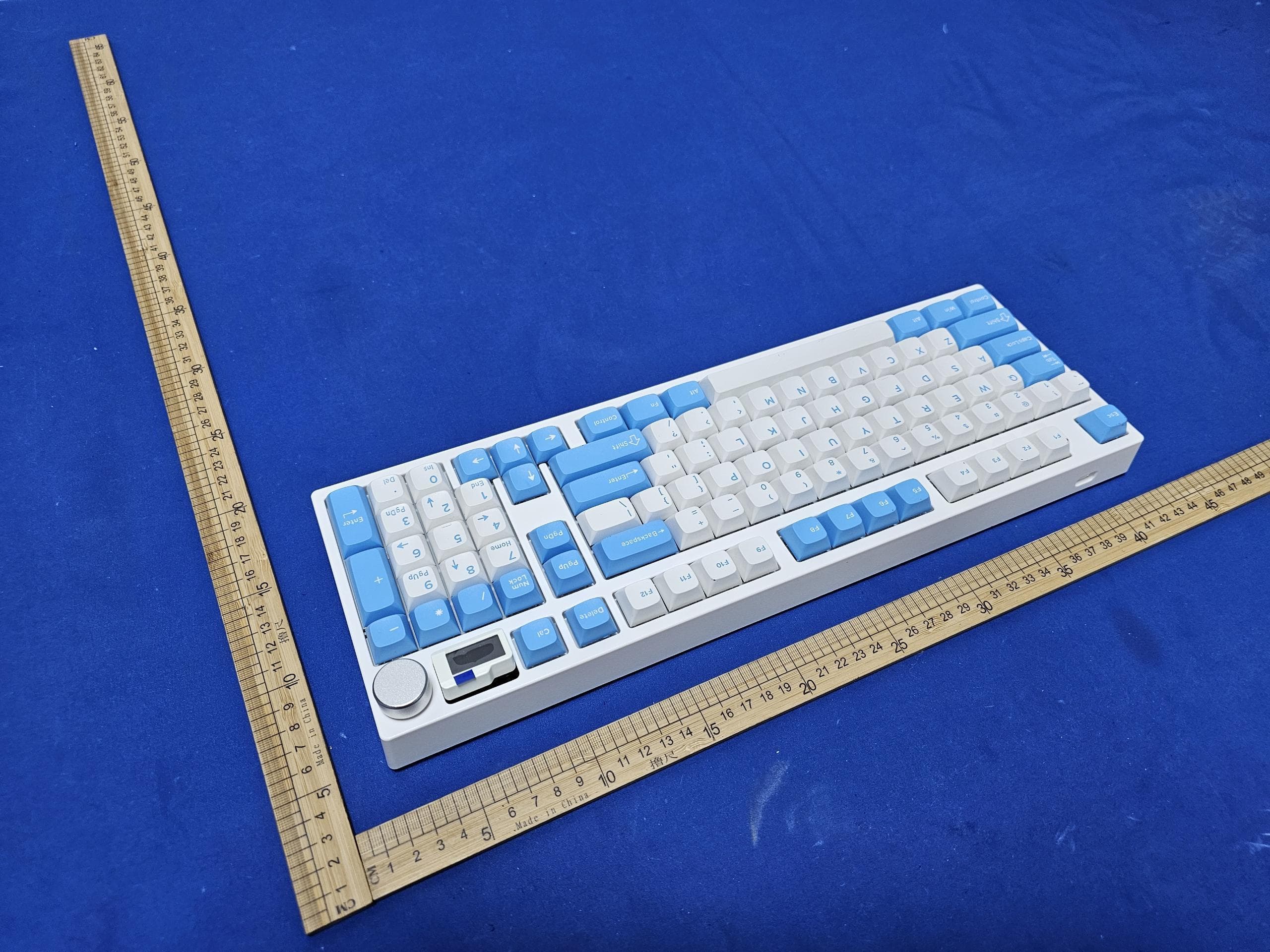
2A4G3-NJ98
Apr 16, 2024Wireless mechanical keyboard
Equipment Class
DTS - Digital Transmission System