2A4IK-M21Dual Channel Noise-cancelling Communication System
OPSMEN Tech Co., Ltd.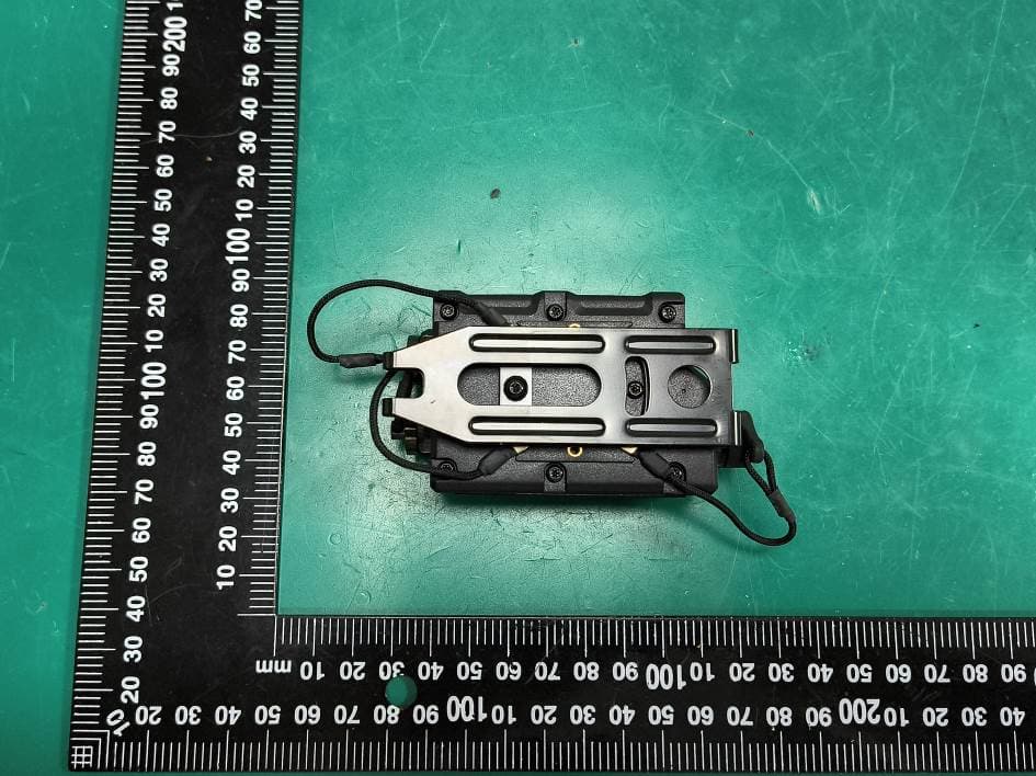
Click to zoom
Application Details
- Equipment Class
- DTS - Digital Transmission System
- Date of Grant
- Jul 21, 2026
- Application Purpose
- Original Equipment
- Equipment Note
- Dual Channel Noise-cancelling Communication System
- Frequency Range
- 2402.00000000 - 2480.00000000
- Company
- OPSMEN Tech Co., Ltd.
- Country
- China
Documents & Files
Document Text
Text extracted from the exhibit documents filed with the FCC. Open a document above to read the original.
Users Manual
M21 IN-EAR MULTI-LEVEL SOUND PICKUP TACTICAL COMMUNICATION HEADSET OVERVIEW Earhook Environmental microphone Anti-tangling slider Earphone plug Clip Earphone unit connector Main PTT Power/menu button PTT 1 PTT 2 COM 1 COM 2 Ear supports Eartips EARMOR ® M21 is an in-ear dual-channel sound pickup and noise reduction communication headset, designed for scenarios that require light weight and high efficiency. It features an NRR rating of 24 dB for sound pickup and noise attenuation. The headset intelligently identifies ambient sounds and processes them with EARMOR’s exclusive acoustic algorithms — amplifying footsteps while suppressing gunshots and other loud impulsive sounds. Equipped with in-ear sound pickup technology, it effectively shields against severe external noise, ensuring consistent, clear and efficient communication transmission. It provides reliable hearing protection alongside convenient and instant communication. This product is highly applicable to tactical missions, security work, emergency response and other professional fields where rapid response and efficient teamwork are essential. ACCESSORIES Product Parameters Eartips (S/M/L) Instruction Manual Type-C cable Main PTT Radio communication cable Earphones Operating Voltage Battery Life Speaker Size Speaker Impedance Battery Type Bluetooth Frequency Supported Protocols Audio Support Charging Interface Audio Jack External Two-Way Radio Interface Operating Temperature Range Bluetooth BLE SBC TYPE-C TYPE-C TYPE-C -20~50 3.2V-4.2V 40H Balanced Armature 5mm*2.73mm*1.93mm 100 Lithium Battery/500 mAh 2402MHz-2480MHz Please connect the earphones plug to the top interface of the PTT. Product Description 1. Connect The Earphones 1) Connect the Type-C connector of the Two-Way Radio cable to COM 1 or COM 2. 2) Insert the plug into the socket. 2. Connect The Two-Way Radio Step 1, Gently insert the ear tip into your ear canal until it fits snugly and creates a seal. Step 2, Secure the ear fin under the ridge of your auricle (outer ear). When the main PTT is powered on, the hearing protection and ambient sound monitoring features are automatically activated. These features are disabled when the unit is powered off. Step 3, Hook the ear hook over the top of your ear and adjust for a secure and comfortable fit. 3. Wear Properly Correct Wearing 4. Hearing Protection COM1 connects to single channel Two-Way Radio, audio in the left earphones. COM2 connects to single channel Two-Way Radio audio in the right earphones. 5. RECEIVE RADIO 1 2 3 Press and hold the button for 2 seconds. After power-on, the volume can be adjusted through five levels by clicking the button. A single click cycles through the volume levels from low to high or turns off the environment sound. Voice prompts: ‘Maximum volume’ / ‘Hear-thru off’. COM1 port connects single channel Two-Way Radio, hold PTT 1 to send audio. Release the PTT button to receive the radio. COM2 port connects single channel Two-Way Radio, hold PTT 2 to send audio. Release the PTT button to receive the radio. 6. PUSH TO TALK 1) When the battery is low, the PTT will issue a prompt. 2) Use a Type-C charging cable to connect the COM1/COM2 interface to a power source for charging. 3) During charging, the red light on the main PTT is on. When fully charged, the red light turns off. 7. BATTERY CHARGING Operating Instructions 1. Main PTT Power On/Off 2. Adjust The Ambient Volume 1.In standby mode, double-press the button to enter the function menu settings. Use the button to select an option. 2.Short press the button to enter a setting. A voice prompt will announce the menu function page.Use the button to select a parameter. Entering and Exiting the Function Menu Function Menu Setting 1. In standby mode, double-click ‘ ’ to enter the function menu with a voice prompt of ’menu’; double-click ‘ ’ again to exit the function menu with a voice prompt of ‘exit menu’. Menu operations are unavailable during Two-Way Radio connection. 3.Short press to confirm, with a voice prompt: ‘saved’, then return to the previous menu page.Use the button to select the next option. 4.After entering the function menu, double-press the button to exit the menu and save the current settings. 2. When entering the function menu, inserting the Two-Way Radio will automatically exit the function menu with a voice prompt of ‘exit menu’, and the current settings will be saved. 3.The function menu will not automatically exit during charging or after an extended period of inactivity within the menu. Function Menu Description Note: Menu operations are unavailable during Two-Way Radio connection. Balanced left and right audio levels Left audio pickup is 4.5dB lower than the right Left audio pickup is 3dB lower than the right Left audio pickup is 1.5dB lower than the right Left audio pickup is 4.5dB higher than the right Left audio pickup is 3dB higher than the right Left audio pickup is 1.5dB higher than the right Check the battery level of M21 Automatic power on Automatic power off/ Note: Battery levels are reported in 10% increments (e.g., 10%, 20%, 30% ... 100%). Balance center Check battery level Restore factory settings Power settings Note: Restores factory settings and automatically powers off. Confirm Cancel Confirm Cancel The device will automatically power off after 2 hours of inactivity Balance Max right Right2 Right1 Max left Left2 Left1 Main unit battery BA EARMOR ® M21 is warranted to be free of defects in material and workmanship for a period of 1 year from the date of original purchase. The warranty is nullified in all of the following situations: 1. The product(s) is/are broken down, reconstructed and/or modified by unauthorized parties. 2. The product(s) is/are damaged through improper use. Production date: see the packaging WARRANTY 123 456 789 *0# 123 456 789 *0# Please read, understand, and follow all safety information in these instructions prior to using the product. Retain these instructions for future reference. For addit…
Text truncated - open the document above for the full version.
Attestation Statements
U.S. AGENT LETTER OF ATTESTATION Date: 2026 -06-12 FEDERAL COMMUNICATIONS COMMISSION Authorization and Evaluation Division 7435 Oakland Mills Road Columbia, MD 21046 Ref: Attestation Statements CFR 47 §2.911(d)(7) Filing FCC ID: 2A4IK-M21 OPSMEN Tech Co., Ltd. certifies that, as of the date of the filing of the application, Iconsigh is our designated U.S. agent for service of process for the above referenced FCC ID. OPSMEN Tech Co., Ltd. accepts to maintain an agent for no less than one year after the grantee has terminated all marketing and importation or the conclusion of any Commission- related proceeding involving the equipment. Iconsigh accepts, as of the date of the filing of the application, the obligation of the designated U.S. agent for service of process for the above referenced FCC ID. Designated U.S. Agent Information: Company Name: Iconsigh Address: 2310 Homestead Road, Suite C1, Los Altos, CA, 94024, United States FRN: 0033398652 Tel.: +1 (408) 320-9867 Email: [email protected] Signed by (printed name): Benjamin Kaur Signature: Applicant: OPSMEN Tech Co., Ltd. Address: Room 601, Building A, No.94 Liwan Road, Liwan District, Guangzhou, Guangdong Province, China FRN: 0031971831 Tel: +86 15989049554 Email: [email protected] Signed by (printed name): Di Sheng Zhang Signature:
External Photos
Bay Area Compliance Laboratories Corp. (Shenzhen) Report No.: 2601T21038E-RF-EXP Page 1 of 6 EUT EXTERNAL PHOTOGRAPHS Bay Area Compliance Laboratories Corp. (Shenzhen) Report No.: 2601T21038E-RF-EXP Page 2 of 6 Bay Area Compliance Laboratories Corp. (Shenzhen) Report No.: 2601T21038E-RF-EXP Page 3 of 6 Bay Area Compliance Laboratories Corp. (Shenzhen) Report No.: 2601T21038E-RF-EXP Page 4 of 6 COM1 COM2 Bay Area Compliance Laboratories Corp. (Shenzhen) Report No.: 2601T21038E-RF-EXP Page 5 of 6 Bay Area Compliance Laboratories Corp. (Shenzhen) Report No.: 2601T21038E-RF-EXP Page 6 of 6
Internal Photos
Bay Area Compliance Laboratories Corp. (Shenzhen) Report No.: 2601T21038E-RF-INP Page 1 of 4 EUT INTERNAL PHOTOGRAPHS Bay Area Compliance Laboratories Corp. (Shenzhen) Report No.: 2601T21038E-RF-INP Page 2 of 4 BT ANT Bay Area Compliance Laboratories Corp. (Shenzhen) Report No.: 2601T21038E-RF-INP Page 3 of 4 Bay Area Compliance Laboratories Corp. (Shenzhen) Report No.: 2601T21038E-RF-INP Page 4 of 4
RF Exposure Info
Bay Area Compliance Laboratories Corp. (Shenzhen) Report No.: 2601T21038E-RF-00B TR-EM-RF003 Page 23 of 75 Version 4.1 RF EXPOSURE EVALUATION RF EXPOSURE EVALUATION Applicable Standard According to FCC §2.1093 and §1.1307(b) (1), systems operating under the provisions of this section shall be operated in a manner that ensure that the public is not exposed to radio frequency energy level in excess of the Commission’s guideline. According to KDB 447498 D01 General RF Exposure Guidance v06. The 1-g and 10-g SAR test exclusion thresholds for 100 MHz to 6 GHz at test separation distances ≤ 50 mm are determined by: [(max. power of channel, including tune-up tolerance, mW)/(min. test separation distance, mm)] • [√f(GHz)] ≤ 3.0 for 1-g SAR and ≤ 7.5 for 10-g extremity SAR, where 1. f(GHz) is the RF channel transmit frequency in GHz. 2. Power and distance are rounded to the nearest mW and mm before calculation. 3. The result is rounded to one decimal place for comparison. 4. When the minimum test separation distance is < 5 mm, a distance of 5 mm is applied to determine SAR test Exclusion. Measurement Result For worst case: Max tune-up conducted power # Mode Frequency (MHz) (dBm)(mW) Distance (mm) Calculated value Threshold (1-g SAR) SAR Test Exclusion BLE2402-24803.0 2.00 50.6 3.0 Yes Result: Compliant
Test Report
Note: The information marked # is provided by the applicant, the laboratory is not responsible for its authenticity and this information can affect the validity of the result in the test report. Customer model name, addresses, names, trademarks etc. are included. This report cannot be reproduced except in full, without prior written approval of the Company. Unless otherwise stated the results shown in this test report refer only to the sample(s) tested. This report is valid only with a valid digital signature. The digital signature may be available only under the Adobe software above version 7.0. This report must not be used by the customer to claim product certification, approval, or endorsement by NVLAP or any agency of the U.S. Government. This report may contain data that are not covered by the NVLAP accreditation and are marked with an asterisk “▼”. Bay Area Compliance Laboratories Corp. (Shenzhen) 5F(B-West) , 6F, 7F, the 3rd Phase of Wan Li Industrial Building D, Shihua Rd, FuTian Free Trade Zone, Shenzhen, China Tel: +86-755-33320018 Fax: +86-755-33320008 www.baclcorp.com.cn TR-EM-RF003 Page 1 of 75 Version 4.1 TEST REPORT Applicant Name:OPSMEN Tech Co., Ltd. Address:Room 601, Building A, No.94 Liwan Road, Liwan District, Guangzhou, Guangdong Province, China Report Number:2601T21038E-RF-00B FCC ID:2A4IK-M21 Test Standard (s) FCC PART 15.247 Sample Description Product Type:Dual Channel Noise-cancelling Communication System Model No.:M21 Multiple Model(s) No.:N/A Trade Mark:EARMOR Date Received:2026/05/11 Issue Date:2026/07/02 Test Result:Pass ▲ ▲ In the configuration tested, the EUT complied with the standards above. Prepared and Checked By:Approved By: Cheeb HuangNancy Wang RF EngineerRF Supervisor Bay Area Compliance Laboratories Corp. (Shenzhen) Report No.: 2601T21038E-RF-00B TR-EM-RF003 Page 2 of 75 Version 4.1 TABLE OF CONTENTS DOCUMENT REVISION HISTORY ..........................................................................................................................3 GENERAL INFORMATION ........................................................................................................................................4 PRODUCT DESCRIPTION FOR EQUIPMENT UNDER TEST (EUT)......................................................................................4 OBJECTIVE ....................................................................................................................................................................4 TEST METHODOLOGY....................................................................................................................................................4 MEASUREMENT UNCERTAINTY .....................................................................................................................................5 TEST FACILITY ..............................................................................................................................................................5 SYSTEM TEST CONFIGURATION ...........................................................................................................................6 SUMMARY OF TEST RESULTS ................................................................................................................................9 TEST EQUIPMENT LIST ..........................................................................................................................................10 REQUIREMENTS AND TEST PROCEDURES ......................................................................................................11 AC LINE CONDUCTED EMISSIONS...............................................................................................................................11 UNWANTED EMISSION FREQUENCIES AND RESTRICTED BANDS .................................................................................13 6 DB EMISSION BANDWIDTH & 99% OCCUPIED BANDWIDTH....................................................................................16 PEAK OUTPUT POWER MEASUREMENT .......................................................................................................................18 POWER SPECTRAL DENSITY ........................................................................................................................................19 100 KHZ BANDWIDTH OF FREQUENCY BAND EDGE....................................................................................................20 CONDUCTED SPURIOUS EMISSION...............................................................................................................................21 DUTY CYCLE ...............................................................................................................................................................22 RF EXPOSURE EVALUATION ................................................................................................................................23 ANTENNA REQUIREMENT .....................................................................................................................................24 TEST DATA AND RESULTS .....................................................................................................................................25 AC LINE CONDUCTED EMISSIONS...............................................................................................................................25 UNWANTED EMISSION FREQUENCIES AND RESTRICTED BANDS .................................................................................28 RF CONDUCTED DATA ................................................................................................................................................62 6dB Emission Bandwidth.......................................................................................................................................63 99% Occupied Bandwidth .................................................................................…
Text truncated - open the document above for the full version.
Test Setup Photos
Bay Area Compliance Laboratories Corp. (Shenzhen) Report No.: 2601T21038E-RF-00B-TSP Page 1 of 3 TEST SETUP PHOTOGRAPHS Connect the Walkie-talkie to COM 1 Port (worst case): Conducted Emissions - Front View Conducted Emissions - Side View Bay Area Compliance Laboratories Corp. (Shenzhen) Report No.: 2601T21038E-RF-00B-TSP Page 2 of 3 Connect two walkie-talkies (worst case): Radiated Emissions View (Below 30MHz) Radiated Emissions View (Below 1 GHz) Bay Area Compliance Laboratories Corp. (Shenzhen) Report No.: 2601T21038E-RF-00B-TSP Page 3 of 3 Radiated Emissions View (1-18 GHz) Radiated Emissions View (18-25 GHz)
Contact Information
Applicant
Di Sheng Zhang(Deputy Manager)
[email protected]Fax: +86 02081179171
Technical Contact
IconsighBenjamin Kaur
2310 Homestead Road Suite C1 · Los Altos, California, 94024 · United States
Test Firm
Bay Area Compliance Laboratories Corp (Shenzhen)Nana Liu
Technical Specifications
| # | Rule Parts | Frequency Range | Power Output |
|---|---|---|---|
| 1 | 15C | 2.40 GHz - 2.48 GHz | 1.80 mW |
Other Applications from OPSMEN Tech Co., Ltd.
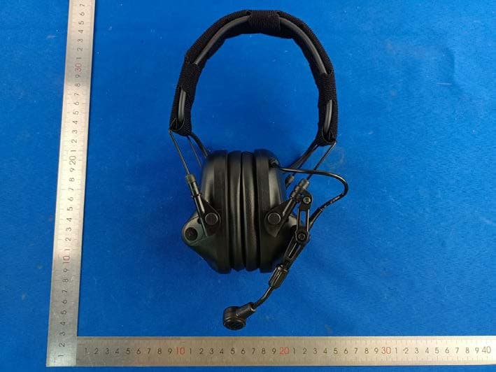
2A4IK-M33
Sep 27, 2023M33 MILPRO HEADSET TACTICAL COMMUNICATION & HEARING PROTECTION
Equipment Class
DSS - Part 15 Spread Spectrum Transmitter