2A4IR-SL9CIL19000Interior ambient lighting
ShenZhen Suncent Auto Parts Technology Company Limited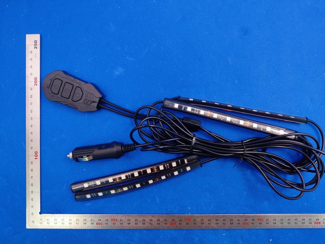
Click to zoom
Application Details
- Equipment Class
- DTS - Digital Transmission System
- Date of Grant
- May 06, 2022
- Application Purpose
- Original Equipment
- Date of Application
- May 06, 2022
- Equipment Note
- Interior ambient lighting
- Frequency Range
- 2402.00000000 - 2480.00000000
- Country
- China
Documents & Files
Document Text
Text extracted from the exhibit documents filed with the FCC. Open a document above to read the original.
Users Manual
Thank you very much for purchasing SEALIGHT. This is an In-car ambient light ambient LED strip. With the APP that comes with the product, users are able to get colors they want. Restrictions and guidelines 1. Do not install the In-car ambient light ambient LED strip near water or in a corrosive location. 2. Do not twist or trample the strip during installation. 3. Please place the wire safely fixed and hidden to prevent damage by tripping over the line and dislodging the light strip. Contents LED strips 4 Control box 1 Remote Control 1 Manual 1 Clip 4 Velcro 4 Anti-vibration stickers 1 Product Specifications Light color RGB Power supply mode Car charger Voltage 12V Control mode App + control box Operating temperature -25–50°C Before installation 1. Open the box and check the contents. 2. Plug the car charger into the cigarette lighter and check whether the LED strip is turned on. Steps 1. Wipe the surface of the mounting position and make sure it is clean, dry and smooth. 2. Place the control box in the armrest box and fix wires of the LED strips with a clip as shown below. 3. Remove the red protection film of the LED strips and paste the strip as shown in the figure below. 4. Firmly press the whole LED strip. Fix the strip with a cable tie. 5. Plug the car charger into the cigarette lighter and the LED strip will light up. It indicates the LED strip is powered on. Control via control box Buttons Functions Switch On/Off Mode Press the button to switch among 4 modes. Color/brightness Press the button to switch among eight colors and press and hold the button to switch among six levels of brightness Using the strip light with remote Buttons Functions ON/OFF Shut down, restore factory settings RANDOM Random switch SOLID Keep it on SPEED+/SPEED- Switching speed BRIGHT+/BRIGHT- Brightness increase and decrease COLOR+/COLOR- Switch color MODE+/MODE- Switch light mode Control via App Download the App. Download and install the Hostrol Smart from App store (for iOS) or Google Play (for Android). Tip: The App is compatible with the following phone systems: iOS 9.0 and above, Android 5.0 and above. Connect with the App 1. Turn on the Bluetooth on your phone and make sure the LED strip is powered on. 2. Turn on the App and tap the "+" icon. FAQs: 1. No light: Check whether the light is properly wired and the interface is tightly inserted. 2. Bluetooth connection fails: Make sure that the Bluetooth on your phone is on. 3. Compatibility fails: Please replace a new phone or upgrade your phone system. 4. Search fails: Keep the product within 2m to your phone. 5. For any questions, please contact our after-sale services. Customer service Warranty: 12 months Email: [email protected] Website:https://sealight-led.com/ NOTE: This equipment has been tested and found to comply with the limits for a Class B digital device, pursuant to part 15 of the FCC Rules. These limits are designed to provide reasonable protection against harmful interference in a residential installation. This equipment generates uses and can radiate radio frequency energy and, if not installed and used in accordance with the instructions, may cause harmful interference to radio communications. However, there is no guarantee that interference will not occur in a particular installation. If this equipment does cause harmful interference to radio or television reception, which can be determined by turning the equipment off and on, the user is encouraged to try to correct the interference by one or more of the following measures: - Reorient or relocate the receiving antenna. - Increase the separation between the equipment and receiver. -Connect the equipment into an outlet on a circuit different from that to which the receiver is connected. -Consult the dealer or an experienced radio/TV technician for help. Changes or modifications not expressly approved by the party responsible for compliance could void the user's authority to operate the equipment. This device complies with Part 15 of the FCC Rules. Operation is subject to the following two conditions: (1) this device may not cause harmful interference, and (2) this device must accept any interference received, including interference that may cause undesired operation.
Cover Letter(s)
ShenZhen Suncent Auto Parts Technology Company Limited Apr.15, 2022 Office of Engineering Technology Federal Communications Commission 7435 Oakland Mills Road Columbia, MD 21046 USA Subject: Explanation of differences between product types FCC ID : 2A4IR-SL9CIL19000 Model Number: SL9CIL19000, SL9CIL18800 To Whom It May Concern: We, The ShenZhen Suncent Auto Parts Technology Company Limited hereby declare that the models are identical except the model name. Except for the different above, no other modification is performed. Sincerely, Signature: ShenZhen Suncent Auto Parts Technology Company Limited Contact person: Yujie Tang
Cover Letter(s)
ShenZhen Suncent Auto Parts Technology Company Limited Agent Authorization Company: ShenZhen Suncent Auto Parts Technology Company Limited Address: 5A1, Building C, Qingchuangcheng, Zhangkeng Community, Minzhi Street, Longhua District, Shenzhen, China Product Name: Interior ambient lighting Model Number(s): SL9CIL19000, SL9CIL18800 Product Description: Interior ambient lighting We authorize MiCOM Labs Inc., 575 Boulder Court, Pleasanton, California 94566, USA, to act on our behalf on all matters concerning the certification of above named equipment. We declare that MiCOM Labs Inc. is allowed to forward all information related to the approval and certification of equipment to the regulatory agencies as required and to discuss any issues concerning the approval application. Any and all acts carried out by MiCOM Labs on our behalf shall have the same effect as acts of our own. Signature: Date: 2022-04-15 Name: Yujie Tang Company: ShenZhen Suncent Auto Parts Technology Company Limited
Cover Letter(s)
ShenZhenSuncentAutoPartsTechnologyCompanyLimited OfficeofEngineeringTechnology FederalCommunicationsCommission 7435OaklandMillsRoad Columbia,MD21046 USA Date:2022-04-12 Subject;RequestforConfidentiality FCCID:2A4IR-SL9CIL19000 ToWhomItMayConcern, PursuanttotheprovisionsoftheCommission’srulesTitle47Sections§0.457and§0.459,we arerequestingtheCommissiontowithholdthefollowingattachment(s)asconfidential documentsfrompublicdisclosureindefinitely. Thesedocumentscontaindetailedsystemandequipmentdescriptionsandareconsideredas proprietaryinformationinoperationoftheequipment.Thepublicdisclosureofthesedocuments mightbeharmfultoourcompanyandwouldgivecompetitorsanunfairadvantageinthemarket. SchematicDiagram BlockDiagram PartsList OperationalDescription Tune-upProcedure Inadditionaltoabovementioneddocuments,inordertocomplywiththemarketingregulations inTitle47CFR§2.803andtheimportationrulesinTitle47CFR§2.1204,whileensuringthat businesssensitiveinformationremainsconfidentialuntiltheactualmarketingofnewly authorizeddevices,werequestShortTermConfidentialityofthefollowingattachment(s); ExternalPhotos TestSetupPhotos InternalPhotos UserManual For45days,pursuanttoPublicNoticeDA04-1705. OR For180dayspursuanttoKDB726920D01. Itisourunderstandingthatallmeasurementtestreports,FCCIDlabelformatand correspondenceduringthecertificationreviewprocesscannotbegrantedasconfidential documentsandthisinformationwillbeavailableforpublicreviewoncethegrantofequipment authorizationisissued. Sincerely ShenZhenSuncentAutoPartsTechnologyCompanyLimited Contactperson:YujieTang
External Photos
Report No.: AGC13808220201AP03 Page 1 of 4 EXTERNAL PHOTOS ALL VIEW OF EUT TOP VIEW OF EUT Report No.: AGC13808220201AP03 Page 2 of 4 BOTTOM VIEW OF EUT FRONT VIEW OF EUT Report No.: AGC13808220201AP03 Page 3 of 4 BACK VIEW OF EUT LEFT VIEW OF EUT Report No.: AGC13808220201AP03 Page 4 of 4 RIGHT VIEW OF EUT PORT VIEW OF EUT ****************************************End of Report****************************************
ID Label/Location Info
FCC ID Label Location 3mm&15mm FCC ID: 2A4IR-SL9CIL19000
Internal Photos
Report No.: AGC13808220201AP03 Page 1 of 2 INTERNAL PHOTOS OPEN VIEW OF EUT (FIGURE 1) ANTENNA CLOSE-UP PHOTO-1 Antenna Report No.: AGC13808220201AP03 Page 2 of 2 INTERNAL VIEW OF EUT (FIGURE 1) INTERNAL VIEW OF EUT (FIGURE 2) ****************************************End of Report****************************************
RF Exposure Info
RF EXPOSURE EVALUATION 1. PRODUCT INFORMATION Product Description Interior ambient lighting Model Name SL9CIL19000 Series Model SL9CIL18800 FCC ID 2A4IR-SL9CIL19000 2. EVALUATION METHOD According to 447498 D01 General RF Exposure Guidance v06 The 1-g and 10-g SAR test exclusion thresholds for 100 MHz to 6 GHz at test separation distances ≤ 50 mm are determined by: [(max. power of channel, including tune-up tolerance, mW)/(min. test separation distance, mm)] ·[√f(GHz)] ≤ 3.0 for 1-g SAR and ≤ 7.5 for 10-g extremity SAR. Where f(GHz) is the RF channel transmit frequency in GHz Power and distance are rounded to the nearest mW and mm before calculation 3. CALCULATION P t =0.191dBm=1.045mW The value of the Maximum output power P t is referred to the test report of the CFR47 §15.247. The result for RF exposure evaluation SAR=(1.045mW / 5mm).[√2.480GHz)]=0.328<3.0 for 1-g SAR and ≤ 7.5 for 10-g extremity SAR. 4. CONCLUSION The SAR evaluation is not required.
Test Report
Page 1 of 42 FCC Test Report Report No.: AGC13808220201FE02 FCC ID : 2A4IR-SL9CIL19000 APPLICATION PURPOSE : Original Equipment PRODUCT DESIGNATION : Interior ambient lighting BRAND NAME : N/A MODEL NAME : SL9CIL19000, SL9CIL18800 APPLICANT : ShenZhen Suncent Auto Parts Technology Company Limited DATE OF ISSUE : Apr. 08, 2022 STANDARD(S) : FCC Part 15.247 REPORT VERSION : V1.0 Attestation of Global Compliance (Shenzhen) Co., Ltd Report No.: AGC13808220201FE02 Page 2 of 42 REPORT REVISE RECORD Report Version Revise Time Issued Date Valid Version Notes V1.0 / Apr. 08, 2022 Valid Initial Release Report No.: AGC13808220201FE02 Page 3 of 42 TABLE OF CONTENTS 1. VERIFICATION OF COMPLIANCE .................................................................................................................. 5 2. GENERAL INFORMATION .............................................................................................................................. 6 2.1. PRODUCT DESCRIPTION ........................................................................................................................ 6 2.2. TABLE OF CARRIER FREQUENCYS ....................................................................................................... 6 2.3. RELATED SUBMITTAL(S)/GRANT(S) ....................................................................................................... 7 2.4. TEST METHODOLOGY ............................................................................................................................. 7 2.5. SPECIAL ACCESSORIES .......................................................................................................................... 7 2.6. EQUIPMENT MODIFICATIONS ................................................................................................................. 7 2.7. ANTENNA REQUIREMENT ....................................................................................................................... 7 3. MEASUREMENT UNCERTAINTY ................................................................................................................... 8 4. DESCRIPTION OF TEST MODES ................................................................................................................... 9 5. SYSTEM TEST CONFIGURATION ................................................................................................................ 10 5.1. CONFIGURATION OF TESTED SYSTEM ............................................................................................... 10 5.2. EQUIPMENT USED IN TESTED SYSTEM .............................................................................................. 10 5.3. SUMMARY OF TEST RESULTS .............................................................................................................. 10 6. TEST FACILITY ............................................................................................................................................... 11 7. PEAK OUTPUT POWER ................................................................................................................................ 12 7.1. MEASUREMENT PROCEDURE .............................................................................................................. 12 7.2. TEST SET-UP (BLOCK DIAGRAM OF CONFIGURATION) .................................................................... 12 7.3. LIMITS AND MEASUREMENT RESULT .................................................................................................. 13 8. BANDWIDTH .................................................................................................................................................. 15 8.1. MEASUREMENT PROCEDURE .............................................................................................................. 15 8.2. TEST SET-UP (BLOCK DIAGRAM OF CONFIGURATION) .................................................................... 15 8.3. LIMITS AND MEASUREMENT RESULTS ............................................................................................... 15 9. CONDUCTED SPURIOUS EMISSION........................................................................................................... 19 9.1. MEASUREMENT PROCEDURE .............................................................................................................. 19 9.2. TEST SET-UP (BLOCK DIAGRAM OF CONFIGURATION) .................................................................... 19 9.3. MEASUREMENT EQUIPMENT USED .................................................................................................... 19 9.4. LIMITS AND MEASUREMENT RESULT .................................................................................................. 19 10. MAXIMUM CONDUCTED OUTPUT POWER SPECTRAL DENSITY ........................................................ 26 Report No.: AGC13808220201FE02 Page 4 of 42 10.1. MEASUREMENT PROCEDURE ............................................................................................................ 26 10.2. TEST SET-UP (BLOCK DIAGRAM OF CONFIGURATION) .................................................................. 26 10.3. MEASUREMENT EQUIPMENT USED .................................................................................................. 26 10.4. LIMITS AND MEASUREMENT RESULT................................................................................................ 26 11. RADIATED EMISSION ................................................................................................................................. 28 11.1. MEASUREMENT PROCEDURE ............................................................................................................ 28 11.2. TEST SETUP .......................................................................................................................................... 29 11.3. LIMITS AND MEASUREMENT RESULT......................................…
Text truncated - open the document above for the full version.
Test Setup Photos
Report No.: AGC13808220201AP02 Page 1 of 2 TEST SETUP PHOTOS RADIATED EMISSION TEST SETUP BELOW 1GHz RADIATED EMISSION TEST SETUP ABOVE 1GHz Report No.: AGC13808220201AP02 Page 2 of 2 RF CONDUCTED TEST SETUP ****************************************End of Report*************************************
Contact Information
Applicant
Yujie Tang
Technical Contact
Test Firm
Attestation of Global Compliance (Shenzhen) Co., LDoris Li
[email protected]+86-755-25234088
Technical Specifications
| # | Rule Parts | Frequency Range | Power Output |
|---|---|---|---|
| 1 | 15C | 2.40 GHz - 2.48 GHz | 1.00 mW |
Other Applications from ShenZhen Suncent Auto Parts Technology Company Limited
2A4IR-SL9CIL19100
Jul 11, 2022Interior ambient light voice model
Equipment Class
DTS - Digital Transmission System