2A4L8-DKA8X8V3Dynamic Smartellite Terminal Ka 8X8 V3
Hisky SCS LTD.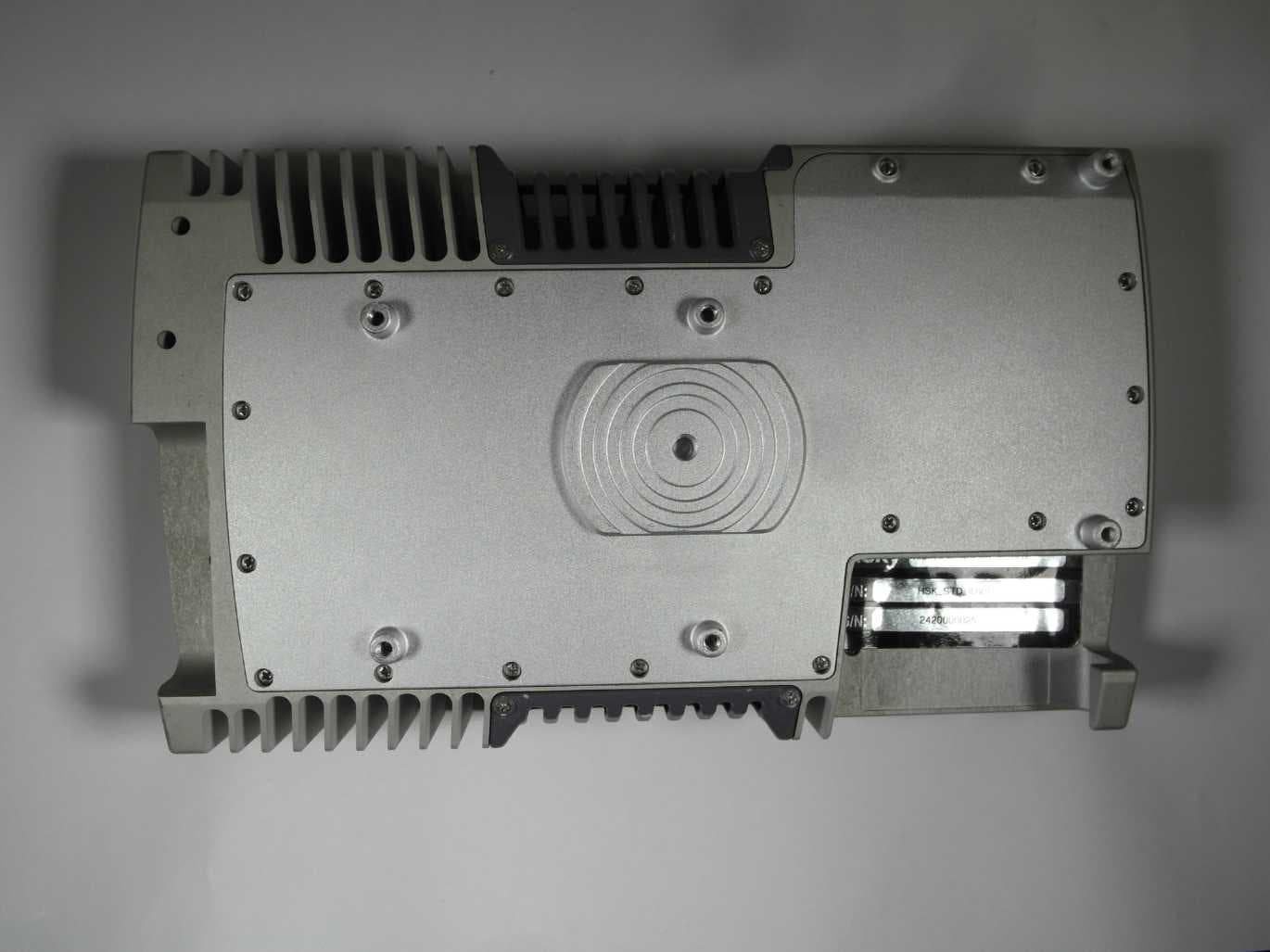
Click to zoom
Application Details
- Equipment Class
- TNB - Licensed Non-Broadcast Station Transmitter
- Date of Grant
- May 21, 2023
- Application Purpose
- Original Equipment
- Date of Application
- May 21, 2023
- Equipment Note
- Dynamic Smartellite Terminal Ka 8X8 V3
- Frequency Range
- 28353.00000000 - 29997.00000000
- Company
- Hisky SCS LTD.
- Country
- Israel
Documents & Files
Document Text
Text extracted from the exhibit documents filed with the FCC. Open a document above to read the original.
Users Manual
1 HSK2411202010 | Dynamic Terminal Ka 8X8 V3 | Quick Start Installation Guide Dynamic Terminal Ka 8X8 V3 Quick Start Installation Guide Document P/N: QSIG0001 Document Version: V.3 Creation Date: October 2020 Last Update: April 1st,2022 2 HSK2411202010 | Dynamic Terminal Ka 8X8 V3 | Quick Start Installation Guide Introduction The Quick Start Guide provides basic information for installation, identification of connectors and visual indicators, as well as regulatory information for the hiSky IoT Ka Dynamic V3 Terminal. Product Description The Dynamic Terminal Ka 8X8 V3 is a compact form-factor device that enables on-the-move satellite connectivity to sensors/smartphones / IoT gateways. The terminal includes an innovative modem and phased array antennas with WI-FI / Bluetooth and Ethernet for user device interfaces. The terminal supports IoT data transmission such as fleet management data, environment conditions, alarm events, sensors loggers, operations, and much more, as well as command and control of sensors and remote systems. Related Documents For information about related documents please navigate to https://www.hiskysat.com. hiSky strives to produce documentation that is technically accurate and easy to use. hiSky welcomes feedback. Send comments to [email protected]. Getting Help For answers to questions or for more information, contact hiSky support at [email protected]. Terminal Overview WARNING: Do not open the terminal or make any changes to the terminal construction. An opening may expose personnel to dangerous voltages or other hazards. There are no user-serviceable parts inside. Avoid placing the Terminal near open flames or any high heat. 3 HSK2411202010 | Dynamic Terminal Ka 8X8 V3 | Quick Start Installation Guide Part Description Mounting Interface 75mm VESA and ¼ Thread interface (see Mount the Terminal). Power Button Terminal on/off button. Power LED Green: Power connected. Red: Error event occurred. Satellite LED Flashing green: Searching for outbound signal or limited line of sight. Green/blue: Terminal sending and receiving satellite traffic. Status LED Flashing green: Trying to register to hiSky network. Green: Terminal registered to hiSky network. Red: Terminal is not able to register to the hiSky network. USB-C Sealing Sleeve Additional mechanical part for sealing the USB-C cable when connected to the terminal. This part is not included in the terminal kit and must be purchased separately. The terminal kit contains the IoT Dynamic Terminal Ka 8X8 V3, and this Quick Start Guide. The kit does not include a bracket, screws, cables, or any other mechanical parts for the installation. Power Supply: Use power cable type: USB-C 65W, 15V / 3.25A (voltage and current standard for 65W). Note: hiSky requires the USB-C cable length to be less than 3 meters for EMI and spurious performance compliance. WARNING: The power supply must be certified for safety, electromagnetic compatibility, and all the regulations in the region where the terminal will operate. Follow all safety instructions according to the manufacturer of the power supply and inverter. The risk of electrical shock and energy hazard of power supply failures should be examined by a qualified technician according to manufacturer instructions. Overview of the First run Operation with hiSky360 App: 1. Initial Login: 4 HSK2411202010 | Dynamic Terminal Ka 8X8 V3 | Quick Start Installation Guide a) Confirm Internet connectivity to your smartphone for the initial Login and software download steps. b) Download the hiSky App from iPhone App Store or Android Google Play Store. c) Click on the hiSky360 App icon. d) Click LOGIN on the main screen. e) Add the account credentials (username and password) related to your hiSky360 account. f) Choose the NMS connection and tap LOGIN. 2. Software Update: a) On the main hiSky360 App screen, click on Software Update. b) Click Ok to continue with the software update process. c) Click on MANAGE UPDATES. d) Click on CHECK FOR UPDATES FROM NMS. e) Select the latest Ka software version for your terminal. f) Download the software files to your smartphone. g) Connect the terminal to a power source (Note: If you are using the USB-C sealing sleeve, please refer to step 6 for information about how to install the cable). h) Ensure the terminal’s mounting side is facing down and hold the power button for 2 seconds until the LED starts flashing green. i) Connect your smartphone to the terminal WI-FI access point. The default SSID is the terminal serial number + the characters WF (for example 2970000000001WF). The default password is admin123. j) Wait for the application to attach to the terminal software. The status will initially show “Attempting”. Wait until it shows “Connected” before proceeding with the upgrade. k) On the main hiSky App screen, click on SOFTWARE UPDATE. l) Click on INSTALL UPDATE. m) At the end of the update, the terminal will reboot. 5 HSK2411202010 | Dynamic Terminal Ka 8X8 V3 | Quick Start Installation Guide 3. Choose Satellite Parameters a) Connect your smartphone to the terminal WI-FI access point. b) Click on the GPS CONFIG on the hiSky main screen. c) Click on REFRESH and SAVE the location parameters. d) Return to the main screen and click on TERMINAL CONFIG. e) In the Satellite Parameters section, ensure that the correct beam number is being used. If not, select the relevant beam number. f) Click SAVE. g) Restart the terminal by pushing the power button. Ensure that the terminal’s mounting side is up before restarting the terminal. h) Use the TERMINAL CONFIG button to integrate between the terminal and the User Device. 4. Active the service plan a) Connect your smartphone to the terminal’s WI-FI access point. b) Login to the hiSky App via a terminal connection. c) On the main hiSky 360 App screen, click on Plan Details. d) Click the ACTIVE PLAN button and wait for confirmation. 6 HSK2411202010 | Dynamic Terminal Ka 8X8 V3 | Quick Start Installation Guide 5. Connect…
Text truncated - open the document above for the full version.
Attestation Statements
hiSky SCS LTD. 24 Amal st. Rosh Ha Ayin, Israel Federal Communication Commission Authorization and Evaluation Division 7435 Oakland Mills Road Columbia, MD 21046 USA Date: 01/03/23 Attestation Statement according to 2.911(d)(7) FCC ID: 2A4L8-DKA8X8V3 TO WHOM IT MAY CONCERN: We, hiSky SCS LTD designate hiSky USA Inc. to act as a U.S. agent for the service of process. Sincerely _______________ (signature & company stamp) Company Name: hiSky SCS LTD Address: 24 Amal st. Rosh Ha Ayin, Israel Name: Ben Shaham Phone: +972 3 6588000 Email: [email protected] _______________ (signature & company stamp) US agent’s Company Name: hiSky USA Inc. Address: 251 Little Falls Drive Wilmington, New Castle Delaware 19808. Name: Shahar Kravitz Phone: +972 54 422 0403 Email: [email protected] hiSky SCS Ltd. P.C. 515250926 hiSky USA Inc. EIN: 92-3525688 hiSky USA Inc.with FCC Registration Number (FRN) hereby acknowledgesthe U.S. agent's obligation for the process service.Further hiSky SCS LTD. Acceptsto maintain anagent for no less than one year after the grantee has terminated all marketing and importation or the conclusion of any Commission-related proceeding involving the equipment. with FCC Registration Number (FRN) 0031985583 0033748203
Cover Letter(s)
2A4L8 -DKA8X8V3
External Photos
Annex A 1-0037/20-02-01_AnnexA External photos of the Equipment Under Test This addendum is electronically signed and valid without handwritten signature. For verification of the electronic signatures, the public keys can be requested at the testing laboratory. Document authorized: Andreas Kurzkurt Testing Manager Radio Communications & EMC CTC advanced GmbHUntertuerkheimer Str. 6-10 66117 Saarbruecken / Germany Phone: +49 681 5 98 - 0 Fax: +49 681 5 98 - 9075 web: ctcadvanced.com e-mail: [email protected] Photos Photo 1 Photo 2 2020-12-04Document No. 1-0037/20-02-01_AnnexA2/5 Photo 3 Photo 4 2020-12-04Document No. 1-0037/20-02-01_AnnexA3/5 Photo 5 Photo 6 2020-12-04Document No. 1-0037/20-02-01_AnnexA4/5 Document history VersionApplied changesDate of release initial release2020-12-04 - END OF DOCUMENT - 2020-12-04Document No. 1-0037/20-02-01_AnnexA5/5
ID Label/Location Info
© Copyright hiSky SCS Ltd. All Rights Reserved. Label and label location: 1. Label contains: 2. Label location: On the bottom of the product. © Copyright hiSky SCS Ltd. All Rights Reserved. 3. Packing label:
Internal Photos
Page 1 of 3 Company Information Date: 15.3.2022 Company Name: hiSky SCS LTD Company Address: 24 Amal st. Rosh Ha Ayin, Israel Company Telephone: 03-6588000 Contact Person: Yori Adi Job Title: NPI & Production Manager Telephone/Mobile: 0545431111 E-mail: [email protected] Product Information Model Number(s): Dynamic Terminal Ka 8X8 V3 Product dimensions (mm): Length, width, height: 220 x 130 x 40mm Product weight (Kg): 1100g Pictures Front view: Top view: Bot view: Page 2 of 3 Digital board: RF Boards: Page 3 of 3
Internal Photos
Annex B 1-0037/20-02-01_AnnexB Internal photos of the Equipment Under Test This addendum is electronically signed and valid without handwritten signature. For verification of the electronic signatures, the public keys can be requested at the testing laboratory. Document authorized: Thomas Vogler Lab Manager Radio Communications & EMC CTC advanced GmbHUntertuerkheimer Str. 6-10 66117 Saarbruecken / Germany Phone: +49 681 5 98 - 0 Fax: +49 681 5 98 - 9075 web: ctcadvanced.com e-mail: [email protected] Photos Photo 1 Photo 2 2021-10-28Document No. 1-0037/20-02-01_AnnexB2/16 Photo 3 Photo 4 2021-10-28Document No. 1-0037/20-02-01_AnnexB3/16 Photo 5 Photo 6 2021-10-28Document No. 1-0037/20-02-01_AnnexB4/16 Photo 7 Photo 8 2021-10-28Document No. 1-0037/20-02-01_AnnexB5/16 Photo 9 Photo 10 2021-10-28Document No. 1-0037/20-02-01_AnnexB6/16 Photo 11 Photo 12 2021-10-28Document No. 1-0037/20-02-01_AnnexB7/16 Photo 13 Photo 14 2021-10-28Document No. 1-0037/20-02-01_AnnexB8/16 Photo 15 Photo 16 2021-10-28Document No. 1-0037/20-02-01_AnnexB9/16 Photo 17 Photo 18 2021-10-28Document No. 1-0037/20-02-01_AnnexB10/16 Photo 19 Photo 20 2021-10-28Document No. 1-0037/20-02-01_AnnexB11/16 Photo 21 Photo 22 2021-10-28Document No. 1-0037/20-02-01_AnnexB12/16 Photo 23 Photo 24 2021-10-28Document No. 1-0037/20-02-01_AnnexB13/16 Photo 25 Photo 26 2021-10-28Document No. 1-0037/20-02-01_AnnexB14/16 Photo 27 2021-10-28Document No. 1-0037/20-02-01_AnnexB15/16 Document history VersionApplied changesDate of release initial release2021-10-28 - END OF DOCUMENT - 2021-10-28Document No. 1-0037/20-02-01_AnnexB16/16
RF Exposure Info
© CTC advanced GmbH Page 1 of 4 BNetzA - CAB - 02/21 - 102 Maximum Permissible Exposure (MPE) & Exposure evaluation Report identification number: 1-0037/20-02-04-A MPE (FCC) Manufacturer: hiSky SCS Ltd Product: Dynamic Terminal Ka 8X8 V3 Kind of test item: Dynamic Smartellite Terminal Ka 8x8 V3 FCC ID: 2A4L8-DKA8X8V3 This test report is electronically signed and valid without handwritten signature. For verification of the electronic signatures, the public keys can be requested at the testing laboratory. Document authorised: Alexander Hnatovskiy Marco Scigliano Lab Manager Testing Manager Radio Communications & EMC Radio Communications & EMC Document History: Version Applied Changes Date of Release Initial Release 2022-10-29 -A Corrected WLAN and BT power according module data sheet. 2023-05-15 Report no.: 1-0037/20-02-04-A © CTC advanced GmbH Page 2 of 4 EUT technologies: Technologies: Max. power Antenna gain max.: [dBi] * Max average EIRP Declared by customer # conducted EIRP Ka-Band 27.5 to 30.0 GHz -- 28.353 GHz: 49.2 dBm 29.253 GHz: 49.0 dBm 29.997 GHz: 51.0 dBm (peak values) -- 36.3 dBm (=4.25 W) A WLAN 2450 MHz -- -- -- 18.5 dBm (= 70.8 mW) B BT EDR / LE -- -- -- 11.7 dBm (= 14.8 mW) B )* worst case of all antenna types, channels and modulations (overrated) Details and origins of the measurements shown in the table above: # Results from: Additional information A 1-0037/20-02-02 CTC advanced GmbH Max PEAK-EIRP page 19 Duty Cycle correction of 3.37% (See Annex A of this document) B Module Datasheet: wl1387mod Collocation overview: Active scenario: Technology 1 2 3 4 Ka-Band x x WLAN 2450 MHz x x BT EDR/LE 2450 MHz x x Report no.: 1-0037/20-02-04-A © CTC advanced GmbH Page 3 of 4 Prediction of MPE limit at given distance - FCC Equation from page 18 of OET Bulletin 65, Edition 97-01 S = PG / 4π R 2 where: S = Power density P = Power input to the antenna G = Antenna gain R = Distance to the center of radiation of the antenna PG = Output Power including antenna gain The table below is excerpted from Table 1B of 47 CFR 1.1310 titled “Limits for Maximum Permissible Exposure (MPE), Limits for General Population/Uncontrolled Exposure” Frequency Range (MHz) Power Density (mW/cm 2 ) Averaging Time (minutes) 300 -1500 f/1500 30 1500 - 100000 1.0 30 where f = Frequency (MHz) Prediction: worst case Technologies: WLAN BT EDR Ka-Band Frequency (MHz) 2450 2450 29997 PG Declared max power (EIRP) 18.5 11.7 36.3 dBm R Distance 20 20 20 cm S MPE limit for uncontrolled exposure 1 1 1 mW/cm 2 Calculated Power density: 0.0141 0.0029 0.8491 mW/cm² Calculated percentage of Limit: 1.41% 0.29% 84.91% Scenario 4: ALL ACTIVE Calculated percentage of Limit: 86.61% Collocation: This prediction demonstrates the following: The power density levels for FCC at a distance of 20 cm are below the maximum levels allowed by regulations. Report no.: 1-0037/20-02-04-A © CTC advanced GmbH Page 4 of 4 Annex A: Duty cycle of the EUT (Ka-Band): Duty Cycle 3.37% Plot data: Transmission Period: 6s Pulse Duration: 202 ms Number of pulses in 360 Seconds = 60 Total Transmission time in 360 Seconds: 60 · 202ms = 12.12s
Test Report
Test report no.: 1-0037/20-02-01_AnnexE © CTC advanced GmbH Page 1 of 35 Annex E This test report annex is electronically signed and valid without handwritten signature. For verification of the electronic signatures, the public keys can be requested at the testing laboratory. Test report annex authorized: Thomas Vogler Lab Manager Radio Communications & EMC Test report no.: 1-0037/20-02-01_AnnexE © CTC advanced GmbH Page 2 of 35 1 Table of contents 1 T a bl e o f c on t e n t s................................................................................................ 2 2 M e a s u r e m e n t r e s u l t s , F C C P a r t 2 5 , S R S P-1 0 1 ....................................................... 3 3 M e a s u r e m e n t r e s u l t s , S p u r i o u s e m i s s i o n s 3 0 M H z - 1 8 G H z ................................. 31 4 M e a s u r e m e n t r e s u l t s , F C C P a r t 1 5 B ................................................................... 34 5 D o c u m e n t h i s t o r y ............................................................................................. 35 Test report no.: 1-0037/20-02-01_AnnexE © CTC advanced GmbH Page 3 of 35 2 Measu re ment result s, F C C Pa rt 25, SRSP-101 This chapter consists of 28 pages including this page. Test report no.: 1-0037/20-02-01_AnnexE © CTC advanced GmbH Page 4 of 35 Plot No. 1 Subclause: -/- Function test Modulated rf-carrier at the lower edge of the band (fl) Measurement within the band Limit: no limits defined This test serves to verify the general function of the EUT and for orientation regarding to the spurious emissions which are expected within the band, furthermore for comparison of the actual power with the rated value at modulated carrier adjusted as close to the lower edge of the operating frequency band. Test results: see plot (an explicit table was not generated) Operating condition of DUT: operating condition 1, see test report chapter 6.4 Test setup: see test report chapter 7.2: Test equipment: see test report chapter 7.2: A031, C107, R001 Remark: Test result: Test passed Environment condition: Date & Time: Fri 29/May/2020 13:18:38 Location: CTC advanced GmbH, Laboratory RC-SYS Temperature: 22 °C Humidity: 55 % Voltage: 230 Vac Setup of measurement equipment: Start frequency: 27.5 GHz Stop frequency: 30 GHz Center frequency: 28.75 GHz Frequency span: 2.5 GHz Resolution-BW: 100 kHz Video-BW: 300 kHz Input attenuation: 20 dB Trace-Mode: Clear Write Detector-Mode: Pos Peak Correction: Directional coupler + 0.0 dB Coaxial cable (C107) + 5.8 dB DUT-Antenna (on-axis) + 0.0 dBi Test antenna (A031) - 15.5 dB BW correction factor + 0.0 dB Atten. between HPA and feedhorn + 0.0 dB Freefield attenuation (28.35GHz, 3.5m) + 72.4 dB Additional attenuation 5.2 dB TOTAL CORRECTION: + 67.9 dB Remarks: Test of general function and measurement for orientation Test report no.: 1-0037/20-02-01_AnnexE © CTC advanced GmbH Page 5 of 35 Plot No. 2 Subclause: -/- Function test Modulated rf-carrier at the lower edge of the band (fl) Determination of the occupied bandwidth Limit: no limits defined Test results: see plot (an explicit table was not generated) Operating condition of DUT: operating condition 1, see test report chapter 6.4 Test setup: see test report chapter 7.2 Test equipment: see test report chapter 7.2: A031, C220, R001 Remark: Test result: Test passed Environment condition: Date & Time: Wed 03/Jun/2020 17:46:14 Location: CTC advanced GmbH, Laboratory RC-SYS Temperature: 22 °C Humidity: 55 % Voltage: 230 Vac Setup of measurement equipment: Start frequency: 28.3505 GHz Stop frequency: 28.3555 GHz Center frequency: 28.353 GHz Frequency span: 5 MHz Resolution-BW: 100 kHz Video-BW: 300 kHz Input attenuation: 6 dB Trace-Mode: Average Detector-Mode: Pos Peak Correction: Directional coupler + 0.0 dB Coaxial cable (C220) + 3.9 dB DUT-Antenna (on-axis) + 0.0 dBi Test antenna (A031) - 15.2 dB BW correction factor + 0.0 dB Atten. between HPA and feedhorn + 0.0 dB Freefield attenuation (28.35GHz, 3m) + 71.0 dB Additional attenuation + 5.4 dB Circular Polarization + 3.0 dB TOTAL CORRECTION: + 68.1 dB Remarks: Determination of the occupied bandwidth. Average measurement. The measured value is about 2 MHz (delta marker) (according to the definition: 99% of the total mean power) The internal function of the analyzer was used for determination. Test report no.: 1-0037/20-02-01_AnnexE © CTC advanced GmbH Page 6 of 35 Plot No. 3 Subclause: -/- Function test Modulated rf-carrier in the middle of the band (fm) Determination of the occupied bandwidth Limit: no limits defined Test results: see plot (an explicit table was not generated) Operating condition of DUT: operating condition 1, see test report chapter 6.4 Test setup: see test report chapter 7.2 Test equipment: see test report chapter 7.2: A031, C220, R001 Remark: Test result: Test passed Environment condition: Date & Time: Wed 03/Jun/2020 17:48:33 Location: CTC advanced GmbH, Laboratory RC-SYS Temperature: 22 °C Humidity: 55 % Voltage: 230 Vac Setup of measurement equipment: Start frequency: 29.2505 GHz Stop frequency: 29.2555 GHz Center frequency: 29.253 GHz Frequency span: 5 MHz Resolution-BW: 100 kHz Video-BW: 300 kHz Input attenuation: 6 dB Trace-Mode: Average Detector-Mode: Pos Peak Correction: Directional coupler + 0.0 dB Coaxial cable (C220) + 4.0 dB DUT-Antenna (on-axis) + 0.0 dBi Test antenna (A031) - 15.8 dB BW correction factor + 0.0 dB Atten. between HPA and feedhorn + 0.0 dB Freefield attenuation (28.35GHz, 3m) + 71.0 dB Additional attenuation + 5.4 dB Circular Polarization + 3.0 dB TOTAL CORRECTION: + 67.6 dB Remarks: Determination of the occupied bandwidth. Average measurement. The measured value is about 1.66 MHz (delta marker) (according to the definition: 99% of the total mean power) The internal function of the analyzer was used for determination. Test report no.: 1-0037/20-02-01_AnnexE © CTC advanced GmbH Page 7 of 35 Plot No. 4 Subclause: -/- Function test Modul…
Text truncated - open the document above for the full version.
Test Report
D - P L - 1 2 0 7 6 - 0 1 - 0 3 BNetzA - CAB - 02/21 - 102 TEST REPORT Test report no.: 1-0037/20-02-02 Testing laboratory Applicant CTC advanced GmbH Untertuerkheimer Strasse 6 – 10 66117 Saarbruecken / Germany Phone: + 49 681 5 98 - 0 Fax: + 49 681 5 98 - 9075 Internet: http://www.ctcadvanced.com e-mail: [email protected] Accredited Testing Laboratory: The testing laboratory (area of testing) is accredited according to DIN EN ISO/IEC 17025 (2005) by the Deutsche Akkreditierungsstelle GmbH (DAkkS) The accreditation is valid for the scope of testing procedures as stated in the accreditation certificate with the registration number: D-PL-12076-01-03 hiSky SCS Ltd 24 Amal St. Park Afek, Rosh Hay’ayin P.O.B 11363 / Israel 4809268 Phone: +972-3-6588000 Contact: Gal Diamant e-mail: [email protected] Phone: +972-3-9646144 Fax: +972-3-6587999 Manufacturer hiSky SCS Ltd 24 Amal St. Park Afek, Rosh Hay’ayin P.O.B 11363 / Israel 4809268 Test standard/s 47 CFR Part 25 Title 47 of the Code of Federal Regulations; Chapter I; Part 25 - Satellite Communications SRSP-101 Technical Requirements for Fixed Earth Stations Operating above 1 GHz in Space Radiocommunication Services and Earth Stations On Board Vessels (ESVs) Operating in the Fixed-Satellite Service For further applied test standards please refer to section 3 of this test report. Test Item Kind of test item: Dynamic Smartellite Terminal Ka 8x8 V3 Model name: Dynamic Terminal Ka 8X8 V3 FCC ID: 2A4L8-DKA8X8V3 Frequency: TX: 28.35 – 28.6, 29.25 – 30.0 GHz, RX: 18.3 – 18.8, 19.7 – 20.2 GHz Characteristics: Tx/Rx, BPSK Power supply: 100 – 240 V AC, 50/60 Hz by Power Supply, 15 V DC via USB-C connector Temperature range: -20 °C to +50 °C This test report is electronically signed and valid without handwriting signature. For verification of the electronic signatures, the public keys can be requested at the testing laboratory. Test report authorized: Test performed: Meheza Walla Thomas Vogler Lab Manager Lab Manager Radio Communications & EMC Radio Communications & EMC Test report no.: 1-0037/20-02-02 Page 2 of 27 1 Table of contents 1 Table of contents ..................................................................................................................................... 2 2 General information ................................................................................................................................. 3 2.1 Notes and disclaimer ..................................................................................................................... 3 2.2 Application details ......................................................................................................................... 3 3 Test standards and references ................................................................................................................ 4 3.1 Test standards ............................................................................................................................... 4 3.2 Measurement guidance ................................................................................................................. 4 3.3 Reporting statements of conformity – decision rule ................................................................... 5 4 Test environment ..................................................................................................................................... 5 5 Test laboratories sub-contracted ............................................................................................................ 5 6 Test item ................................................................................................................................................... 6 6.1 General Description....................................................................................................................... 6 6.2 List of components........................................................................................................................ 7 6.3 Antenna system(s) ........................................................................................................................ 7 6.4 Operating conditions ..................................................................................................................... 7 6.5 Additional information................................................................................................................... 7 7 Description of the test setup ................................................................................................................... 8 7.1 Shielded fully anechoic chamber.................................................................................................. 9 7.2 Radiated measurements > 18 GHz .............................................................................................. 11 7.3 Radiated measurements > 50 GHz .............................................................................................. 11 8 Sequence of testing ............................................................................................................................... 13 8.1 Sequence of testing radiated spurious 9 kHz to 30 MHz ........................................................... 13 8.2 Sequence of testing radiated spurious 30 MHz to 1 GHz........................................................... 14 8.3 Sequence of testing radiated spurious 1 GHz to 18 GHz ........................................................... 15 8.4 Sequence of testing radiated spurious above 18 GHz ............................................................... 16 8.5 Sequence of testing radiated spurious above 50 GHz with external mixers ............................ 17 9 Measurement results ............................................................................................................................. 18 9.1 Summary ................................................................................…
Text truncated - open the document above for the full version.
Test Report
Ka-band terminal performance Revision: 0.1 Reference Number: HSK2411202023 Creation Data: May 10, 2022 Last Update: August 21, 2022 This document is the proprietary property of hiSky Ltd. Copying or otherwise distributing the information contained herein is a breach of confidentiality agreement 1 Control and Monitoring Functions Control and Monitoring Functions is a mechanism designed to facilitate spectrum sharing with other devices in the Wireless network. This mechanism makes sure our devices won’t interfere with other users by waiting for the RX link to start before transmitting These measurements were performed under normal test conditions. 1.1 CMF state diagram 1.2 Setup diagram Setup components: • “Ka dynamic terminal” – EUT • “Spectrum Analyzer” - used to measure the time between the Rx link opened to the EUT transmit • “Satellite simulator” - hiSky lab equipment to simulate a Satellite for measurements • “RX” – RX antenna for the EUT and “Satellite simulator” to the “Spectrum analyzer” • “TX” – TX antenna for the “Satellite simulator” 1.3 Testing results: • Processor monitoring - in this test we ensure the transition stops whenever the processor senses a sub-system failure. We also ensure that the Tx disabling is taking less than 50ms after the subsystem failure. • Transmit subsystem monitoring – in this test we ensure that our EUT inhibits transmission in case of: o Loss of frequency lock o absence of Local Oscillator (LO) output signal No later than 50ms seconds after any of these fault conditions of the transmit frequency generation sub-system occurs, the EUT enterED the "non-valid" state until the transmit sub- system monitoring function has determined that all fault conditions have been cleared. • Power-on/Reset – we checked that the EUT is stop transmitting whit in less than 50ms from the moment we rest it. We also checked that there is no transmitting during power-on (until every subprocess is done and the RX link is achieved) • Control Channel (CC) and Response Channel (RC) – we ensure that the EUT cannot transmit unless it correctly receives the CC messages from the ACF. We also ensure that in case the EUT didn’t receive the correct command after a period of less than 1 sec, the EUT entered a “non–valid” state and stop transmitting. • Network control commands – in this test we ensure that the EUT can retain a unique identification in the network and receive commands from the ACF through its CC(s) and execute those commands. We ensure that the EUT stops transmitting in less than 50ms after getting “Transmission Disable commands”. • Initial burst transmission – in this test we make sure that: o The EUT won’t start the transmission of initial bursts before having confirmation by the local means of determination of the cessation of emissions or from the ACF via an external control channel. o The duty cycle of the burst retransmission does not exceed 0.2 % o Each burst is not carrying more than the minimum number of data bytes excluding the burst preambles and the FEC coding bits necessary to establish synchronization o The initial burst is transmitted at an EIRP no greater than the maximum allowed. o The duration between two successive bursts is not less than the required ACF response time as declared by the applicant • Inhibition of transmissions – the EUT stops transmitting in case of loss of receive carriers. The EUT enters to “transmission disable” mode in less the 50mS Test Time Status Processor monitoring <50mS pass Transmit subsystem monitoring <50mS pass Power-on/Reset <50mS Pass Control Channel (CC) and Response Channel (RC) - Pass Network control commands <50mS Pass Initial burst transmission - Pass Inhibition of transmissions <50mS pass 2 Blocking performance The Blocking performance is a measure of how well the receiver blocks high power signals outside the receive frequency that can prevent the reception of signals inside the receive frequency band. 2.1 Setup diagram Setup components: • “Ku dynamic terminal” – EUT • “Signal generator – first signal” - the in-band signal generator • “Signal generator – out of band signal” – the out of band signal generator • Combiner – used to combine “Satellite simulator” and “Signal generator” signal • “ANT” – Horn 14dBi Ku antenna, used to transmit the signal to the EUT • PC – for controlling • “Spectrum analyzer” – for measuring the receiver compression point 2.2 Results F…
Text truncated - open the document above for the full version.
Contact Information
Applicant
Yori Adi
Test Firm
cetecom advanced GmbHGerald Schmidt
Technical Specifications
| # | Rule Parts | Frequency Range | Power Output | Emission | Tolerance |
|---|---|---|---|---|---|
| 1 | 25 | 28.35 GHz - 30.00 GHz | 125.9 W | 2M00FXD | 0.3190000000 ppm |
Other Applications from Hisky SCS LTD.
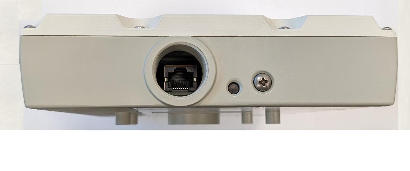
2A4L8-FKU8X8V2
Jan 22, 2023KU8X8 FIXED TERMINAL V2
Equipment Class
TNB - Licensed Non-Broadcast Station Transmitter