2A4PW-7076Wireless Remote
Mile Marker Industries, Inc.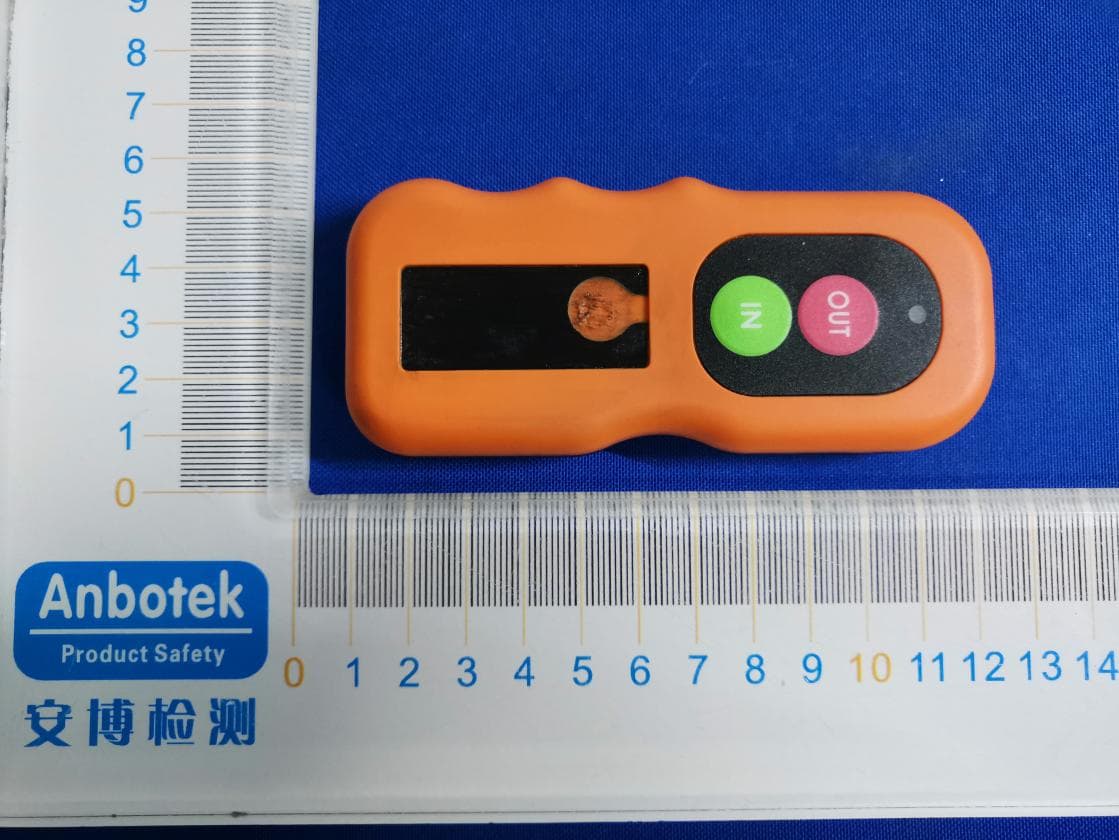
Click to zoom
Application Details
- Equipment Class
- DSC - Part 15 Security/Remote Control Transmitter
- Date of Grant
- Mar 17, 2022
- Application Purpose
- Original Equipment
- Date of Application
- Mar 17, 2022
- Equipment Note
- Wireless Remote
- Frequency Range
- 433.92000000 - 433.92000000
- Company
- Mile Marker Industries, Inc.
- Country
- United States
Documents & Files
Document Text
Text extracted from the exhibit documents filed with the FCC. Open a document above to read the original.
Users Manual
PLUG N PLAY WIRELESS WINCH REMOTE Model Number: 7076 2121 Blount Road Pompano Beach, FL 33069 MileMarker.com 1.800.886.8647PAGE 1 IMPORTANT If your control box has any other pin configuration other than the standard IP67 waterproof 4 pin, use the pig tail provided (Item 3) ITEMS IN THE BOX 1. USB cable 2. Mounting hardware 3. Pig tail (plug) 4. Remote control holder 5. Remote control 6. Control box IP67 waterproof 2 3 5 6 1 4 2121 Blount Road Pompano Beach, FL 33069 MileMarker.com 1.800.886.8647PAGE 2 INSTALLATION: PLUG N PLAY If your Mile Marker winch features the IP67 waterproof connection, then simply plug the control box into your solenoid box just as you would your wired remote control. The wireless receiver has an oblong button for power, and once “ON” (indicated by a RED light), the unit is ready for use. PAIRING YOUR WIRELESS REMOTE TO THE CONTROL BOX Your new Mile Marker Plug N Play wireless winch remote control has already been paired with your control box at the factory. However, if your wireless remote control loses its signal to the control box, or you want to pair additional remotes (up to five), follow the instructions below to pair. Press the white oblong button on the front of the control box. The button will turn red. Press the round receiver button on the back of the control box (next to the cable). The button will turn red. On your wir eless remote control, press and hold the OUT button only (usually one to three seconds). The round button on the back of the control box will start to flash. Shortly thereafter your winch will start to winch out, release the OUT button. Your remote control is now paired to the receiver. To prevent cross contamination with other wireless devices, the round receiver button will only be active for approximately 5 seconds. Have your wireless remote control ready prior to pushing the round receiver button. In the event the remote control did not pair, repeat steps 2 and 3. Charge your wireless remote control prior to this operation. Refer to reverse side for charging instructions. STEP 2 STEP 3 NOTES STEP 1 oblong receiver button round receiver button OUT button STEP 1A WARNING Make sure to disconnect battery first! The solenoid box has 4 screws on the bottom as shown in the image below. Remove these screws and lift box cover up. sol 1 WEIGHT: A1 SHEET 1 OF 1SCALE:2:1 DWG NO. TITLE: REVISION DO NOT SCALE DRAWING MATERIAL: DATE SIGNATURE NAME DEBUR AND BREAK SHARP EDGES FINISH: UNLESS OTHERWISE SPECIFIED: DIMENSIONS ARE IN MILLIMETERS SURFACE FINISH: TOLERANCES: LINEAR: ANGULAR: Q.A MFG APPV'D CHK'D DRAWN Green IN Black OUT Red GROUND Yellow 12 V + STEP 2A Wire the pig tail (plug) according to the diagram below. Black OUT Red GROUND Green IN Yellow 12V + Alignment Pin PIGTAIL PLACEMENT OPTIONS There are many options for the placement of your new plug. Here are a few options we suggest: 1. Slide plug under the solenoid box and attach accordingly on the outside of the solenoid. 2. Drill the top side of the box cover (on the right side of the Mile Marker logo), then slide in the head of the pig tail (plug). 3. Drill the right side of the box cover toward the top and then slide in the head of the pig tail (plug). screws 2121 Blount Road Pompano Beach, FL 33069 MileMarker.com 1.800.886.8647PAGE 3 PRG INSTALLATION: USING PIGTAIL 2121 Blount Road Pompano Beach, FL 33069 MileMarker.com 1.800.886.8647PAGE 4 The wireless winch remote is factory tested to 50’. However, there are numerous things that can affect the final distance you can get out of your wireless winch remote. Even though we are using omni directional antennas, radio waves don’t really travel the same distance in all directions. Water, mud, snow, ice, humidity, trees, rock, mountains, walls, doors, elevator shafts, people, and other obstacles offer varying degrees of weak signal, which cause the radio frequency (RF) pattern to be irregular and unpredictable and can shorten the range considerably. If you are using the transmitter and find this happening, try moving your position around the vehicle. Your body’s magnetic field will affect the performance of your transmitter. Things like mobile phones and other transmitting devices will also affect range, including others using this same device that are within range of you. Final installation location of your control box is very important for maximum range. You will need an assistant to help you do this. Test several locations with your vehicle to get your optimum range. To get the maximum range you will have to adjust the position of the control box in your vehicle. Vehicles have different ways that they act with radio waves, so you may have to try several locations until you get the best reception. Note that with any wireless systems, its very difficult to predict the propagation of radio waves and detect the presence of interfering signals. The system was designed to be used at less than 50’ line of sight, in an outdoor area void of obstructions and objects that create reflections and not near any sources of RF interference. CHARGING YOUR WIRELESS REMOTE CONTROL Your new Mile Marker wireless winch remote control comes with a non removable rechargeable Li-ion battery. The battery is approximately 20% charged at the factory. Therefore, fully charge your wireless winch remote control before you use it. Please note, that while charging, all wireless functions will automatically shut off. This means you will not be able to use your device while it is being charged. To charge your wireless winch remote control, use the USB cable that is supplied. While charging, the Blue indicator light will flash. Once fully charged it will turn solid Blue and stay Blue until you disconnect it. For safety purposes, your remote comes with a power management chip which prevents overcharging. However, it’s still best to unplug once fully charged. Avoid using your wireless winch remote control if it feels hot after being fully charged. Temperatures can be high when…
Text truncated - open the document above for the full version.
Cover Letter(s)
Mile Marker Industries, Inc. Office of Engineering Technology Federal Communications Commission 7435 Oakland Mills Road Columbia, MD 21046 USA Date: 2022-03-14 Subject; Request for Confidentiality FCC ID: 2A4PW-7076 To Whom It May Concern, Pursuant to the provisions of the Commission’s rules Title 47 Sections §0.457 and §0.459, we are requesting the Commission to withhold the following attachment(s) as confidential documents from public disclosure indefinitely. These documents contain detailed system and equipment descriptions and are considered as proprietary information in operation of the equipment. The public disclosure of these documents might be harmful to our company and would give competitors an unfair advantage in the market. Schematic Diagram Block Diagram Operational Description SW SECURITY DESCRIPTION Parts List Tune up In additional to above mentioned documents, in order to comply with the marketing regulations in Title 47 CFR §2.803 and the importation rules in Title 47 CFR §2.1204, while ensuring that business sensitive information remains confidential until the actual marketing of newly authorized devices, we request Short Term Confidentiality of the following attachment(s); External Photos Test Setup Photos Internal Photos User Manual For 45 days, pursuant to Public Notice DA 04-1705. OR For 180 days pursuant to KDB 726920 D01. It is our understanding that all measurement test reports, FCC ID label format and correspondence during the certification review process cannot be granted as confidential documents and this information will be available for public review once the grant of equipment authorization is issued. Sincerely, Signature: Name: John Laub Title: President
Cover Letter(s)
Mile Marker Industries, Inc. Letter of Authorization Company: Mile Marker Industries, Inc. Address: 2121 Blount Road, Pompano Beach, Florida 33069 USA Product Name: Wireless Remote Model Number(s): 7076 Product Description: Wireless Remote We authorize MiCOM Labs Inc., 575 Boulder Court, Pleasanton, California 94566, USA, to act on our behalf on all matters concerning the certification of above named equipment. We declare that MiCOM Labs Inc. is allowed to forward all information related to the approval and certification of equipment to the regulatory agencies as required and to discuss any issues concerning the approval application. Any and all acts carried out by MiCOM Labs on our behalf shall have the same effect as acts of our own. Signature: Date: 2022-03-14 Name: John Laub Title: President Company: Mile Marker Industries, Inc.
External Photos
FCC ID: 2A4PW-7076
ID Label/Location Info
Label Location: Product Name: Wireless Remote Model No.: 7076 FCC: 2A4PW-7076
Internal Photos
FCC ID: 2A4PW-7076 ANT
Test Report
ReportNo.:18220WC20030101FCCID:2A4PW-7076Page1of31 Code:AB-RF-05-a FCCTestReport ClientName:MileMarkerIndustries,Inc. Address:2121BlountRoad,PompanoBeach,Florida33069USA ProductName:WirelessRemote Date:Mar.14,2022 ShenzhenAnbotekComplianceLaboratoryLimited ReportNo.:18220WC20030101FCCID:2A4PW-7076Page2of31 Code:AB-RF-05-a Contents 1.GeneralInformation ............................................................................................................................................... 4 1.1.ClientInformation ....................................................................................................................................... 4 1.2.DescriptionofDevice(EUT) ..................................................................................................................... 4 1.3.AuxiliaryEquipmentUsedDuringTest ................................................................................................... 5 1.4.DescriptionofTestModes ........................................................................................................................ 5 1.5.Listofchannels ........................................................................................................................................... 5 1.6.DescriptionOfTestSetup ......................................................................................................................... 6 1.7.TestEquipmentList .................................................................................................................................... 7 1.8.MeasurementUncertainty ......................................................................................................................... 8 1.9.DescriptionofTestFacility ........................................................................................................................ 8 2.SummaryofTestResults ..................................................................................................................................... 9 3.ConductedEmissionTest ................................................................................................................................... 10 3.1.TestStandardandLimit .......................................................................................................................... 10 3.2.TestSetup .................................................................................................................................................. 10 3.3.TestProcedure .......................................................................................................................................... 10 3.4.TestData .................................................................................................................................................... 10 4.RadiationSpuriousEmissionandBandEdge ................................................................................................ 11 4.1.TestStandardandLimit .......................................................................................................................... 11 4.2.TestSetup .................................................................................................................................................. 12 4.3.TestProcedure .......................................................................................................................................... 13 4.4.TestData .................................................................................................................................................... 13 5.20DBOccupyBandwidthTest ........................................................................................................................... 19 5.1.TestStandardandLimit .......................................................................................................................... 19 5.2.TestSetup .................................................................................................................................................. 19 5.3.TestProcedure .......................................................................................................................................... 19 5.4.TestData .................................................................................................................................................... 19 6.DwellTimeTest .................................................................................................................................................... 21 6.1.TestStandardandLimit .......................................................................................................................... 21 6.2.TestSetup .................................................................................................................................................. 21 6.3.TestProcedure .......................................................................................................................................... 21 6.4.TestData .................................................................................................................................................... 21 7.AntennaRequirement ......................................................................................................................................... 23 7.1.TestStandardandRequirement ............................................................................................................ 23 7.2.AntennaConnectedConstruction .......................................................................................................... 23 APPENDIXI--TESTSETUPPHOTOGRAPH ................................................................................................... 24 APPENDIXII--EXTERNALPHOTOGRAPH ..................................................................................................... 25 APPENDIXIII--INTERNALPHOTOGRAPH .........................................…
Text truncated - open the document above for the full version.
Test Setup Photos
FCC ID: 2A4PW-7076 Photo of Radiation Emission Test
Contact Information
Applicant
John Laub(President)
Technical Contact
Test Firm
Shenzhen Anbotek Compliance Laboratory LimitedJeff Zhu
Technical Specifications
| # | Rule Parts | Frequency Range | Power Output |
|---|---|---|---|
| 1 | 15.231 | 433.92 MHz - 433.92 MHz | - |