2A4TE-PF-09GPS wireless fence
Shenzhen Realink Technology Co., Ltd.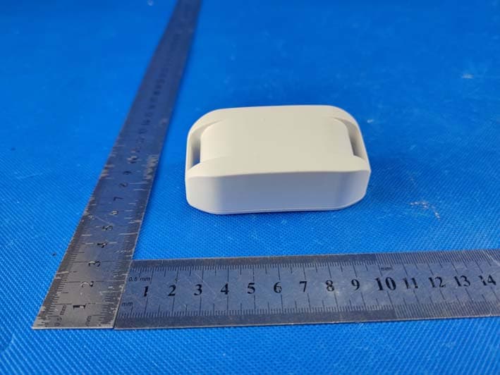
Click to zoom
Application Details
- Equipment Class
- JAB - Part 15 Class B Digital Device
- Date of Grant
- Jan 09, 2023
- Application Purpose
- Original Equipment
- Date of Application
- Jan 09, 2023
- Equipment Note
- GPS wireless fence
- Country
- China
Documents & Files
Document Text
Text extracted from the exhibit documents filed with the FCC. Open a document above to read the original.
Users Manual
[email protected] Model NO.: PF-09 GPS Wireless Fence User Manual -2--1- Table of contents About GPS wireless fence Components Key Definitions Operating Guide Training Guide 2 3 3 4 Step 1: Charge Receiver Collar(s) Step 2: Set Up Receiver Collar(s) Step 3: Prepare Receiver Collar(s) Step 4: Place the Boundary Flags Step 5: Fit Receiver Collar(s) 4 5 8 8 10 12 Statements 12 About GPS wireless fence ! NOTE GPS Wireless Dog Fence is designed FOR OUTDOOR USE ONLY. The GPS electronic fence equipment is designed to create a dog park to contain your dog safely playing around in your yard without Digging and Burying Wires. The newly upgraded system can cover 990 meters depending on the Customer’s needs. There are four modes of position- ing functions (GPS+ BD + Galilean +Glonass), and supporting up to three positioning patterns. The system operates the alarm system (beep/ vibration /shock) to warn dogs while he goes beyond the boundary zone you set up and remains peaceful while pet are within the boundary zone. -4--3- The icon of the “ ”will remain flickering when the battery on the receiver is low. IMPORTANT Components Key Definitions 12 46 3 57 Operating Guide Step 1: Charge Receiver Collar(s) The USB Charger is designed to plug into a standard AC wall outlet. The Collar Light will remain red flickering when the Receiver Collar(s) is charging properly. “ ” The light will turn red when charging is complete. “ ” Battery Status: The battery power can support device working continu- ously for 25 hours in the power-on state, and user can press any key to view the battery status in standby state. If the device isn’t in use for more than 10 minutes, it will enter deep hibernation state. Charge Jack Contact Points GPS Receiver Collar: Designed to transmit and receive the GPS signal to set up the boundary. Charger: Charges the Receiver Collar(s). Collar Belt: Used in conjunction with Receiver Collar(s). USB Cable: Connect with the charger to charge the Receiver Collar(s). Contact Points: Deliver the safe static correction when your pet cross over the boundary. Test Light: Used with Receiver Collar(s) to test the boundary. The hole on the Test Light can be used as wrench to fix metal probes. Training Flags: The visual reminders for your pet to know the boundary. 1 2 3 4 5 6 7 -6--5- 1Press the power key “ ” for 3 sec to turn on the device. The display will first flickering “ ” , then takes 1-3 minutes wait until the display numbers reaches to six or more. Now, it’s ready for next steps. Step 2: Set Up Receiver Collar(s) ON/OFFModeIncreaseReduce The “ ” shows signal strength. Please use this system with 2 or more Frames “ ” or “ ” Poor GPS signal, this area is not suitable for GPS wireless system. “ ” : Fair GPS signal, this area is OK but not perfect. “ ” or “ ” : Strong GPS signal, perfect area to set up GPS wireless system. TIPS 2. Long Press: Press the mode key “ ” for 3 sec to enter the distance setting mode, and the flickering number on the screen means radius range. (For example: "03"=30 meters radius range, "10"=100 meters.) You can use the “ ” and “ ”keys to adjust the distance accordingly. The system will automatically remember the setting after 5 sec. The "99" will be the maximum, and the largest range will be 990 meters. 3. Short Press: Press the mode key “ ” for 1 sec to set the alarm mode (beep, vibration and shock). Use the “ ” and “ ” key to adjust the strength of the alarm. After selecting a pattern that works best for your dog reasonably, we can step to train. Up to 990M in Radius Press for 3 seconds -8--7- Step 4: Place the Boundary Flags The Boundary Flags are visual reminders for your pet to cognize where the Boundary Zone is located. The Receiver Collar(s) will activate within 1-2 feet of the Boundary Flags. Please mark the spot you set up the boundary, it will be the center of the boundary. You will need to TURN ON the collar at the same spot to remain the boundary's fixedness. For example, you turn on the collars 1 meter to the left side, the whole bound- ary will be shifted 1 meter to the left. IMPORTANT 1~6 LowStrong 10 ONOFF 1~10 LowStrong Beep Modes: 0~1. With "1", beep mode ON, with "0" for beep OFF. Virbration Modes: 0~6. With "0", the vibration mode off, and 1-6 modes can be set as the corresponding intensity of vibration that pets can receive. Shock Modes: 0~10. With "0", the shock mode off, and 1-10 modes can be set as the corresponding intensity of shock that pets can receive. Step 3: Prepare Receiver Collar(s) Install the contact Points and Collar Belt for Receiver Collar(s). TURN ON the collar in the same spot everytime . Whole boundary will be shifted if you DO NOT turn on the collar in the same spot. 1 m 1 m -10--9- 1. Make sure the Receiver Collar Battery is properly charged. 2. Hold the Test Light contacts to the Contact Points. Test light instructions. 1. Follow the step 2 to set up your desired zone. 2. Using the Test Light, hold the Receiver Collar(s) at your pet’s neck height. 3. Walking toward to the edge of the desired zone you set up until the Receiver Collar(s) beeps and the Test Light Flashes. 4. Place a Training Flag in the ground. 5. Walk back into the desired zone until the beeping stops. 6. Repeat this process around the boundary zone until it is marked with Boundary Flags every 10 feet. Step 5: Fit the Receiver Collar(s) 1. Start with your pet standing comfortably. 2. Center the Contact Points underneath your pet’s neck, touching the skin. 3. You may need to trim the hair in the area of the Contact Points, but never shave the dog’s neck. 4. Check the tightness of the Receiver Collar by inserting one finger between the end of a Contact Point and your pet’s neck. The fit should be snug but not constricting. 5. Trim the Collar Belt to the length fitting your dog’s neck. To assure a proper fit, please follow steps below: • The proper fit and placement of your Receiver Collar is important for effective training. The Contact Points must have direct cont…
Text truncated - open the document above for the full version.
Cover Letter(s)
Sincerely, Name/Title: Yu Miao/Manager Company: Shenzhen Realink Technology Co., Ltd. Address: 1026 maker building, 72-6 huanguan south road, xintian community, guanhu street Longhua district, shenzhen, Guangdong China Phone: +86-0755-32910756 Fax: +86-0755-32910568 E-Mail: [email protected]
External Photos
Page 20 of 29 Report No.: AIT22121914E2 Dongguan Yaxu (AiT) Technology Limited No.22, Jinqianling Third Street, Jitigang, Huangjiang,Dongguan, Guangdong, China. 7 APPENDIX-Photographs of EUT Constructional Details Page 21 of 29 Report No.: AIT22121914E2 Dongguan Yaxu (AiT) Technology Limited No.22, Jinqianling Third Street, Jitigang, Huangjiang,Dongguan, Guangdong, China.
ID Label/Location Info
FCC ID Label FCC ID: 2A4TE-PF-09
Internal Photos
Page1 of 5ReportNo.: AIT22121914E2 DongguanYaxu (AiT) TechnologyLimited No.22,Jinqianling3rd Street,Jitigang, Huangjiang,Dongguan,Guangdong,China. InternalPhoto s Photo1 Photo2 Page2 of 5ReportNo.: AIT22121914E2 DongguanYaxu (AiT) TechnologyLimited No.22,Jinqianling3rd Street,Jitigang, Huangjiang,Dongguan,Guangdong,China. Photo3 Photo4 Page3 of 5ReportNo.: AIT22121914E2 DongguanYaxu (AiT) TechnologyLimited No.22,Jinqianling3rd Street,Jitigang, Huangjiang,Dongguan,Guangdong,China. Photo5 Photo6 Antenna Page4 of 5ReportNo.: AIT22121914E2 DongguanYaxu (AiT) TechnologyLimited No.22,Jinqianling3rd Street,Jitigang, Huangjiang,Dongguan,Guangdong,China. Photo 7 Photo 8 Page5 of 5ReportNo.: AIT22121914E2 DongguanYaxu (AiT) TechnologyLimited No.22,Jinqianling3rd Street,Jitigang, Huangjiang,Dongguan,Guangdong,China. Photo 9 Photo 10 ------End------
Test Report
Page1 of29ReportNo .: AIT22121914E2 DongguanYaxu(AiT)TechnologyLimited No.22,JinqianlingThirdStreet,Jitigang, Huangjiang,Dongguan,Guangdong,China. FCC Test Report For ShenzhenRealinkTechnologyCo., Ltd EUT Name:GPSwirelessfence ModelNo:PF-09 BrandName:N/A FCC ID:2A4TE-PF-09 PreparedBy: DongguanYaxu(AiT)TechnologyLimited Dateof Receipt: Dec.19,2022 Dateof Test: Dec.19~29,2022 Dateof Issue: Dec.30,2022 This reportshallnot be reproducedexceptin full, withoutthe writtenapproval of DongguanYaxu(AiT)TechnologyLimited Page2 of29ReportNo .: AIT22121914E2 DongguanYaxu(AiT)TechnologyLimited No.22,JinqianlingThirdStreet,Jitigang, Huangjiang,Dongguan,Guangdong,China. ClientInformation: Applicant:ShenzhenRealinkTechnologyCo., Ltd Applicantadd .:1026makerbuilding,72-6 huanguansouthroad,xintian community,guanhustreet,Longhuadistrict,shenzhen, Guangdong, China EUT Information: EUT Name::GPSwirelessfence ModelNo::PF-09 BrandName::N/A Test Sample:EngineeringSampleNo.: AIT22121914-1 Test standardused:FCC Part 15 SubpartB This devicedescribedabovehas beentestedby DongguanYaxu(AiT)TechnologyLimitedand the test resultsshowthat the equipmentundertest (EUT)is in compliancewith the FCC requirements.And it is applicableonly to the testedsampleidentifiedin the report. Reviewedby:Approvedby: SimbahuangSeal Chen Page3 of29ReportNo .: AIT22121914E2 DongguanYaxu(AiT)TechnologyLimited No.22,JinqianlingThirdStreet,Jitigang, Huangjiang,Dongguan,Guangdong,China. 1 Contents Page COVERPAGE 1CONTENTS............................................................................................................................................................3 2TESTSUMMARY...................................................................................................................................................4 2.1MEASUREMENTUNCERTAINTY............................................................................................................................5 3TESTFACILITY.....................................................................................................................................................6 3.1DEVIATIONFROMSTANDARD..............................................................................................................................6 3.2ABNORMALITIESFROMSTANDARDCONDITIONS...................................................................................................6 4GENERALINFORMATION...................................................................................................................................7 4.1GENERALDESCRIPTIONOFEUT ........................................................................................................................7 4.2EUT TESTMODE...............................................................................................................................................8 4.3DESCRIPTIONOFTEST SETUP............................................................................................................................8 4.4PERIPHERALLIST...............................................................................................................................................9 4.5TESTPERIPHERALLIST......................................................................................................................................9 4.6EUT PERIPHERALLIST......................................................................................................................................9 5EQUIPMENTSLISTFORALL TESTITEMS......................................................................................................10 6EMISSIONTESTRESULTS................................................................................................................................11 6.1MAINSTERMINALSDISTURBANCEVOLTAGEMEASUREMENT.............................................................................11 6.1.1E.U.T.Operation...............................................................................................................11 6.1.2Test Specification..............................................................................................................11 6.1.3MeasurementData ............................................................................................................12 6.2RADIATEDEMISSIONMEASUREMENT................................................................................................................13 6.2.1E.U.T.Operation...............................................................................................................13 6.2.2Test Specification..............................................................................................................13 6.2.3MeasurementData ............................................................................................................14 6.2.4Test Setupphotograph......................................................................................................19 7APPENDIX-PHOTOGRAPHSOF EUT CONSTRUCTIONALDETAILS...........................................................20 Page4 of29ReportNo .: AIT22121914E2 DongguanYaxu(AiT)TechnologyLimited No.22,JinqianlingThirdStreet,Jitigang, Huangjiang,Dongguan,Guangdong,China. 2 Test Summary TestTest RequirementTest MethodCriterionResult MainsTerminals DisturbanceVoltage, 150kHzto 30MHz FCCPart 15 SubpartB ANSIC63.4:20 14 LimitsN/A RadiatedEmissions 30MHzto 1GHz FCCPart 15 SubpartB ANSIC63.4:20 14 LimitsPASS Note:N/A, not applicable,this productspoweredby DC power. Page5 of29ReportNo .: AIT22121914E2 DongguanYaxu(AiT)TechnologyLimited No.22,JinqianlingThirdStreet,Jitigang, Huangjiang,Dongguan,Guangdong,China. 2.1 MeasurementUncertainty The reportuncertaintyof measurementy±U, whereexpendeduncertaintyUis basedon a standard uncertaintyMultipliedby a coveragefactorofk=2, providinga levelof confidenceof approximately95% . No.ItemFrequencyRangeU , Value 1PowerLine ConductedEmission150KHz~30MHz1. 20 dB 2DisturbancePower…
Text truncated - open the document above for the full version.
Test Report
The Holy bond Electronics Co., Ltd. Antenna Test Report Customer: Project: Product: GPS Antenna—陶瓷天线 Report date: 2022.12.13 Prepared by : 刘才亮 Checked by : Eason Huang Approved by : 深圳市亿圣邦科技有限公司 深圳市亿圣邦科技有限公司 1 Content 1. Product Overview 2.Test Result 2.1 GPS Antenna VSWR 2.2 GPS Antenna Gain/Efficiency/3D DATE 3. Conclusions 深圳市亿圣邦科技有限公司 2 1. Product Overview & Dimension 深圳市亿圣邦科技有限公司 3 GPS天线实物 2. Test Result 2.1 GPS Antenna VSWR/S11 深圳市亿圣邦科技有限公司 4 深圳市亿圣邦科技有限公司 5 2. Test Result 2.2 GPS Antenna Gain/Efficiency/3D DATE 3. Conclusions 深圳市亿圣邦科技有限公司 6 Thank you
Test Setup Photos
Page 19 of 29 Report No.: AIT22121914E2 Dongguan Yaxu (AiT) Technology Limited No.22, Jinqianling Third Street, Jitigang, Huangjiang,Dongguan, Guangdong, China. 6.2.4 Test Setup photograph
Contact Information
Applicant
Yu Miao(Manager)
Test Firm
Dongguan Yaxu (AiT) Technology LimitedCoin Tang
[email protected]+86 0769-82020499-21
Technical Specifications
| # | Rule Parts | Frequency Range | Power Output |
|---|---|---|---|
| 1 | 15B | - | - |
Other Applications from Shenzhen Realink Technology Co., Ltd.
2A4TE-AG19
Sep 10, 2025Smart Pet Fence System
Equipment Class
DSC - Part 15 Security/Remote Control Transmitter