Text extracted from the exhibit documents filed with the FCC. Open a document above to read the original.
FM0131_V01 Approver Check Design Confirm GM PM FAE QA Sales Customer MODEL: PS4 Game Controller PART NO: NJP411 VERSION: V1.0 Version 1.0 NJP411 Preliminary 1 Document Title Denomination:PS4 Game Controller Part No. :NJP411 Circuit Diagram Version Part No. Function Version NJP411 PS4 Game Controller V1.0 Revision History Revision No. History Page NO. AutherDate V1.0 Issue 7 Joy 2022/3/14 Version 1.0 NJP411 Preliminary 2 1. Product Features: This product is based on PS4 Game Controller,It is suitable for PS4 console and compatible with PS4 Bluetooth controller. Equipping with 4 Analog Axes, 2 Analog Buttons and 16 Digital Buttons, as well as 2-Points Touchpad, RGB Light Bar, Big and Small Vibration, Headset Jack and 6-axis Motion Sensor, it also supports the wired connection to PC and the wireless pairing function. 2. Product block diagram: NJP411 (BT IC) USB Funtion、 Light Bar LED Headset Jack Speaker X003M (6-axis Motion Sensor) Vibration Digital、Analog Key Funtion X003C Touch Pad X0040 P4-04 Version 1.0 NJP411 Preliminary 3 3. Function configuration diagram: 4. Product Specifications: 4.1. Bluetooth Connection (Bluetooth 2.1+EDR specification) Support. 4.2. USB Wird Connection/Pairing (USB 1.1/USB 2.0 and Micro USB) Support. 4.3. Button & Stick Button Digital/Analog Button Digital/Analog PS D Up D OPTION D Down D SHARE D L1 D L3 D L2 D/A(0 to 255) R3 D R1 D Circle D R2 D/A(0 to 255) Cross D Touch Key D Triangle D Left Stick (x-axis) A(0 to 255,center:128) Square D Left Stick (y-axis) A(0 to 255,center:128) Right D Right Stick (x-axis) A(0 to 255,center:128) Left D Right Stick (y-axis) A(0 to 255,center:128) Big Motor Small Motor USB (Micro B) & Light Bar Headset Jack Speaker Version 1.0 NJP411 Preliminary 4 4.4. Touchpad (supports the capacitive touchpad with 2-point touch) SPEC. Value Range Number of Detectable Touch Points 2 Pressure-sensitive Format Capacitance X-axis Touch Coordinate Range 0 to1919 Y-axis Touch Coordinate Range 0 to 941 (0 , 0) Touch Pad Coordinate System x y Touch Area 4.5. Light Bar (consists of RGB LED for indicating the status, with 256 shades per color channel brightness) LED Value Range Red 0:off,1 to 255 : On Green Blue On the main menu for PS4 console, each player's color is indicated: Player 1: Blue (64), Player 2: Red (64), Player 3: Green (64), Player 4: Purple (Red=64, Blue=64). 4.6. Vibration(builds in 2 vibration motors. The larger one is at left hand side of the controller, and smaller one is at right hand side of the controller, with 256 levels per motor's vibration strength) Motor Value Range Small (Right Side) 0:stop,1 to 255 : rotate Large (Left Side) 4.7. Motion Sensor(divides into the acceleration sensor and angular velocity sensor. Each has 3-axis direction with a resolution of 65536 per axis) Sensor Value Range Acceleration ± 4 G X-axis -32768↔0000↔32767 0G : 0 、 ±1G : ±8192 Y-axis Z-axis Angular Velocity (Gyro) ± 2000 dps X-axis -32768↔0000↔32767 (When still : 0) Y-axis Z-axis Version 1.0 NJP411 Preliminary 5 4.8. Audio Feature(builds in a mono speaker and stereo headset jack) Audio Spec. Speaker Built-in,Mono 。 Headset Jack Support Stereo Headset、Microphone 。 4.9. Power (Rechargeable Lithium Battery) Type Voltage (± 0.1 V) Fully Charged DC3.93to DC 4.20V 2 Bars Left DC3.71 to DC 3.92V 1 Bars Left DC3.57 to DC 3.70V No Bar Left Under DC3.41V In Hibernate Under DC3.40V 5. Pairing: 5.1 Wired Pairing Method: Use Micro-USB cable to connect PS4 console to finish pairing. After that, press PS Key to connect wirelessly. 5.2 Wireless Pairing Method: Press SHARE key first when the controller is in Hibernate. Then, press PS Key for 3 seconds, and LED Bar starts to flash twice periodically to enter the wireless pairing mode. Now, the devices support PS4 controller can be searched and paired by Bluetooth. 6. Offline calibration function: 6.1. Please remove the USB cable and disconnect the wireless connection first, let the handle go to sleep (the channel light is off), and place it on the desktop 6.2. First press the SQUARE and CROSS keys, and then press the PS key, when the channel light starts to flash red slowly, it will enter the offline calibration function. At this time, please remove your fingers and avoid vibration to the desktop and handle, which will cause calibration failure. 6.3. When the channel light flashes slowly for 2 seconds, the calibration is successful, and when the channel light flashes slowly for 4 seconds, the calibration fails. After the calibration fails, please perform the offline calibration again . 7. Electrical Specifications: (Ta=0 C ~ 70 C 、Power Input = DC 3.7V ) 7.1. Operation Voltage: DC 3.4V to DC 4.2V ( ± 0.1V) 7.2. Operation Current: 7.3. Current in Hibernate:: Under 35uA Min 50mA ± 10mA (@ DC 3.7V) Max Under 200mA (@ DC 3.7V) Version 1.0 NJP411 Preliminary 6 ▓ NJP411 Package Dimensions: ▓ X003M Package Dimensions: Version 1.0 NJP411 Preliminary 7 ▓ X003C Package Dimensions: Version 1.0 NJP411 Preliminary 8 FCC Caution: This device complies with part 15 of the FCC Rules. Operation is subject to the following two conditions: (1) This device may not cause harmful interference, and (2) this device must accept any interference received, including interference that may cause undesired operation. Any Changes or modifications not expressly approved by the party responsible for compliance could void the user's authority to operate the equipment. Note: This equipment has been tested and found to comply with the limits for a Class B digital device, pursuant to part 15 of the FCC Rules. These limits are designed to provide reasonable protection against harmful interference in a residential installation. This equipment generates uses and can radiate radio frequency energy and, if not installed and used in accordance with the instructions, may cause harmful interference to radio communications. However, there is no guarantee that interference will not occur in a particular installation. If this equipment does cause harmful…
Text truncated - open the document above for the full version.
Dongguan NYGA Electronics Co., Ltd Agent Authorization Company: Dongguan NYGA Electronics Co., Ltd Address: 10 Dajiang Road, Hengjiang village, Chashan Town, Dongguan City, Guangdong Province, China Product Name: PS4 game controller Model Number(s): NJP411, NJP410, NJP412, NJP413, NJP414, NJP415, NJP416, NJP417, NJP418, NJP419 Product Description: PS4 game controller We authorize MiCOM Labs Inc., 575 Boulder Court, Pleasanton, California 94566, USA, to act on our behalf on all matters concerning the certification of above named equipment. We declare that MiCOM Labs Inc. is allowed to forward all information related to the approval and certification of equipment to the regulatory agencies as required and to discuss any issues concerning the approval application. Any and all acts carried out by MiCOM Labs on our behalf shall have the same effect as acts of our own. Signature: Date: 2022/03/29 Name: XuebinJIANG Title: Manager Company: Dongguan NYGA Electronics Co., Ltd
Dongguan NYGA Electronics Co., Ltd Office of Engineering Technology Federal Communications Commission 7435 Oakland Mills Road Columbia, MD 21046 USA Date: 2022/03/29 Subject; Request for Confidentiality FCC ID: 2A54A-NJP411 To Whom It May Concern, Pursuant to the provisions of the Commission’s rules Title 47 Sections §0.457 and §0.459, we are requesting the Commission to withhold the following attachment(s) as confidential documents from public disclosure indefinitely. These documents contain detailed system and equipment descriptions and are considered as proprietary information in operation of the equipment. The public disclosure of these documents might be harmful to our company and would give competitors an unfair advantage in the market. Schematic Diagram Block Diagram Operational Description In additional to above mentioned documents, in order to comply with the marketing regulations in Title 47 CFR §2.803 and the importation rules in Title 47 CFR §2.1204, while ensuring that business sensitive information remains confidential until the actual marketing of newly authorized devices, we request Short Term Confidentiality of the following attachment(s); User Manual For 45 days, pursuant to Public Notice DA 04-1705. OR For 180 days pursuantto KDB 726920 D01. It is our understanding that all measurement test reports, FCC ID label format and correspondence during the certification review process cannot be granted as confidential documents and this information will be available for public review once the grant of equipment authorization is issued. Sincerely, Signature: Name: XuebinJIANG Title: Manager
Dongguan NYGA Electronics Co., Ltd Model Difference 2022.03.29 EUT NAME: PS4 game controller FCC ID: 2A54A-NJP411 MODEL : NJP411, NJP410, NJP412, NJP413, NJP414, NJP415, NJP416, NJP417, NJP418, NJP419 All the model are the same circuit and RF module, except model names. Sincerely Client’s signature Client’s name / title : XuebinJIANG / Manager Contact information / address: 10 Dajiang Road, Hengjiang village, Chashan Town, Dongguan City, Guangdong Province, China
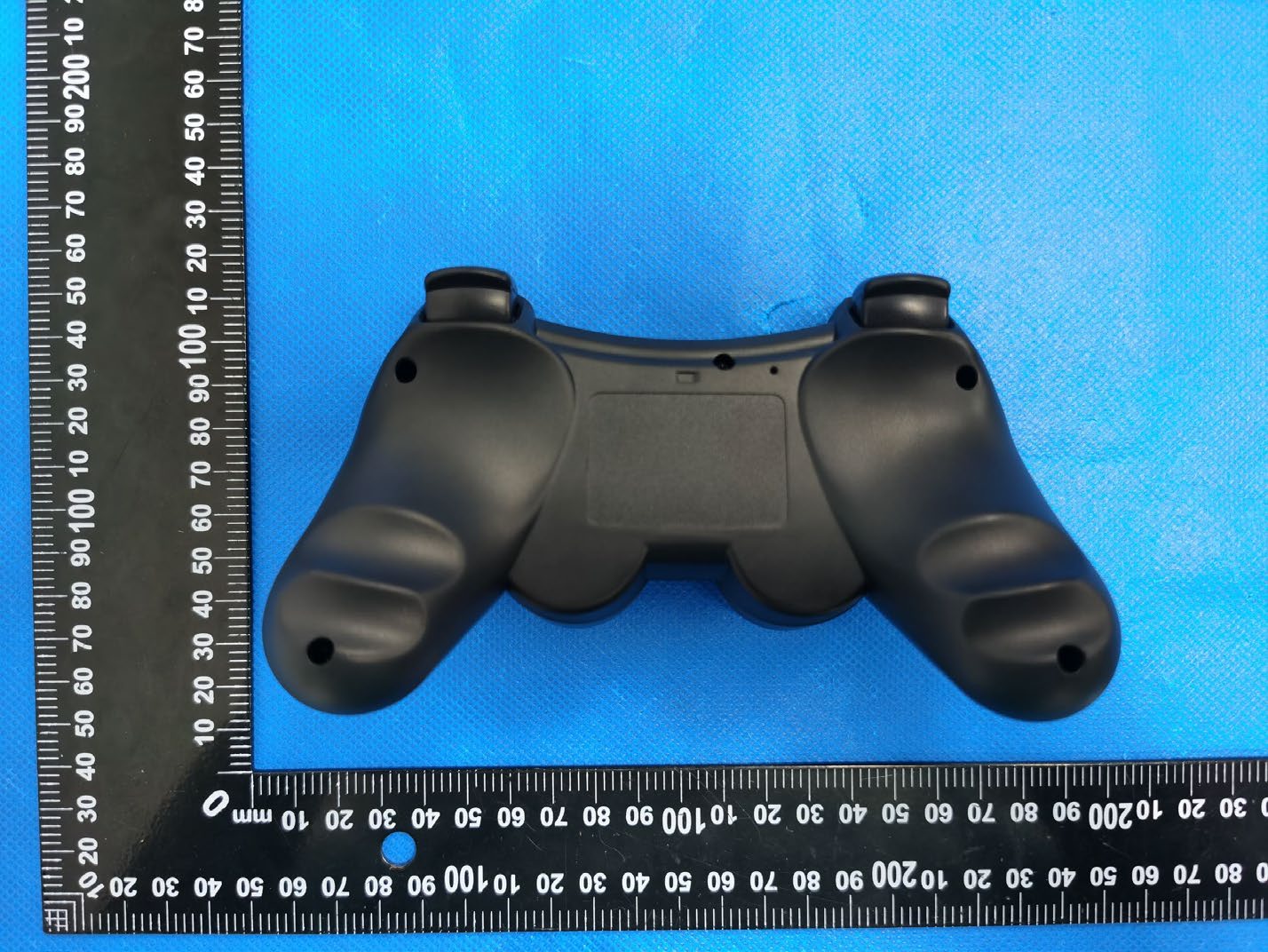
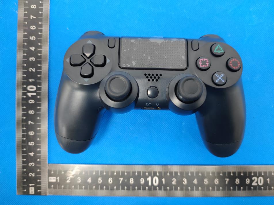
External Photos
Size:20*10mm PS4 game controller FCC ID: 2A54A-NJP411 Label location
RF EXPOSURE EVALUATION METHOD FCC ID: 2A54A-NJP411 Applicable standard: In accordance with FCC 47 CFR part 2 (2.1093) this device has been defined as a portable device which is defined as a transmitting device designed to be used so that the radiating structure(s) of the device is/are within 20 centimeters of the body of the user. Portable devices must be evaluated using the specified in FCC 47 CFR part 2 (2.1093) and ANSI/IEEEC95.1-1992. and had been tested in accordance with the measurement methods and procedures specified in IEEE 1528-2003. Per FCC KDB 447498 D01 v06, the 1-g and 10-g SAR test exclusion thresholds for 100 MHz to 6 GHz at test separation distances s 50 mm are determined by: SAR Test Exclusion Thresholds for 100 MHz – 6 GHz and ≤ 50 mm Approximate SAR Test Exclusion Power Thresholds at Selected Frequencies and Test Separation Distances are illustrated in the following Table. The 1-g and 10-g SAR test exclusion thresholds for 100 MHz to 6 GHz at test separation distances ≤ 50 mm are determined by: [(max. power of channel, including tune-up tolerance, mW)/(min. test separation distance, mm)] · [√f(GHz)] ≤ 3.0 for 1-g SAR and ≤ 7.5 for 10-g extremity SAR,where f(GHz) is the RF channel transmit frequency in GHz Power and distance are rounded to the nearest mW and mm before calculation The result is rounded to one decimal place for comparison The test exclusions are applicable only when the minimum test separation distance is ≤ 50 mm and for transmission frequencies between 100 MHz and 6 GHz. When the minimum test separation distance is < 5 mm, a distance of 5 mm is applied to determine SAR test exclusion. BT Modulation Test Channel Output Power (dBm) Limit (dBm) GFSK Low 0.14 21 GFSK Middle -0.07 21 GFSK High -0.81 21 π/4DQPSK Low 0.55 21 π/4DQPSK Middle 0.41 21 π/4DQPSK High -0.35 21 8DPSK Low 0.7 21 8DPSK Middle 0.53 21 8DPSK High -0.21 21 max possible output power (PK,conducted):0±1dBm -6.72dBi logarithmic terms convert to numeric result is nearly 0.21 1dBm=1.26mW 2402MHz [(max. power of channel, including tune-up tolerance, mW)/(min. test separation distance,mm)] · [√f(GHz)]= 1.26/5*√2.402=0.391≤3.0 2441MHz [(max. power of channel, including tune-up tolerance, mW)/(min. test separation distance,mm)] · [√f(GHz)]= 1.26/5*√2.441=0.394≤3.0 2480MHz [(max. power of channel, including tune-up tolerance, mW)/(min. test separation distance,mm)] · [√f(GHz)]= 1.26/5*√2.48=0.397≤3.0 Conclusion: 1. [(max. power of channel, including tune-up tolerance, mW)/(min. test separation distance, mm)] * [√f(GHz)] < 3.0. 2. SAR Test Exclusion Thresholds is 3.0 for separation distance 5mm. Therefore, SAR test is not required.
No.:BCTC/RF-EMC-005 Page 1 of 83 Edition:A.4 TEST REPORT Shenzhen BCTC Testing Co., Ltd. Report No.: BCTC2203279915E Applicant: Dongguan NYGA Electronics Co., Ltd Product Name: PS4 game controller Model/Type Ref.: NJP411 Tested Date: 2022-03-22 to 2022-03-29 Issued Date: 2022-03-29 Report No.: BCTC2203279915E No.:BCTC/RF-EMC-005 Page 2 of 83 Edition:A.4 FCC ID: 2A54A-NJP411 The test report is effective only with both signature and specialized stamp. This result(s) shown in this report refer only to the sample(s) tested. Without written approval of Shenzhen BCTC Testing Co., Ltd, this report can’t be reproduced except in full. The tested sample(s) and the sample information are provided by the client. Product Name: PS4 game controller Trademark: N/A Model/Type Ref.: NJP411 NJP410, NJP412, NJP413, NJP414, NJP415, NJP416, NJP417, NJP418, NJP419 Prepared For: Dongguan NYGA Electronics Co., Ltd Address: 10 Dajiang Road, Hengjiang village, Chashan Town, Dongguan City, Guangdong Province, China Manufacturer: Dongguan NYGA Electronics Co., Ltd Address: 10 Dajiang Road, Hengjiang village, Chashan Town, Dongguan City, Guangdong Province, China Prepared By: Shenzhen BCTC Testing Co., Ltd. Address: 1-2/F., Building B, Pengzhou Industrial Park, No.158, Fuyuan 1st Road, Tangwei, Fuhai Subdistrict, Bao'an District, Shenzhen, Guangdong, China Sample Received Date: 2022-03-22 Sample tested Date: 2022-03-22 to 2022-03-29 Issue Date: 2022-03-29 Report No.: BCTC2203279915E Test Standards: FCC Part15.247 ANSI C63.10-2013 Test Results: PASS Remark: This is Bluetooth Classic radio test report. Tested by: Approved by: Lei Chen/Project Handler Zero Zhou/Reviewer Report No.: BCTC2203279915E No.:BCTC/RF-EMC-005 Page 3 of 83 Edition:A.4 Table Of Content Test Report Declaration Page 1. Version .................................................................................................................. 5 2. Test Summary ....................................................................................................... 6 3. Measurement Uncertainty ..................................................................................... 7 4. Product Information And Test Setup ..................................................................... 8 4.1 Product Information ............................................................................................... 8 4.2 Test Setup Configuration ...................................................................................... 8 4.4 Channel List .......................................................................................................... 9 4.5 Test Mode ............................................................................................................. 9 4.6 Table Of Parameters Of Text Software Setting ..................................................... 9 5. Test Facility And Test Instrument Used ............................................................... 10 5.1 Test Facility ......................................................................................................... 10 5.2 Test Instrument Used .......................................................................................... 10 6. Conducted Emissions .......................................................................................... 12 6.1 Block Diagram Of Test Setup .............................................................................. 12 6.2 Limit .................................................................................................................... 12 6.3 Test Procedure ................................................................................................... 12 6.4 EUT Operating Conditions .................................................................................. 13 6.5 Test Result .......................................................................................................... 14 7. Radiated Emissions ............................................................................................. 16 7.1 Block Diagram Of Test Setup .............................................................................. 16 7.2 Limit .................................................................................................................... 17 7.3 Test Procedure ................................................................................................... 18 7.4 EUT Operating Conditions .................................................................................. 19 7.5 Test Result .......................................................................................................... 19 8. Radiated Band Emission Measurement And Restricted Bands Of Operation ..... 23 8.1 Block Diagram Of Test Setup .............................................................................. 23 8.2 Limit .................................................................................................................... 23 8.3 Test Procedure ................................................................................................... 24 8.4 EUT Operating Conditions .................................................................................. 24 8.5 Test Result .......................................................................................................... 25 9. Conducted Emission ........................................................................................... 26 9.1 Block Diagram Of Test Setup .............................................................................. 26 9.2 Limit .................................................................................................................... 26 9.3 Test Procedure ................................................................................................... 26 9.4 Test Result .......................................................................................................... 27 10. 20 DB Bandwidth .....................…
Text truncated - open the document above for the full version.
Report No.: BCTC2203279915E No.:BCTC/RF-EMC-005 Page 81 of 83 Edition:A.4 17. EUT Test Setup Photographs Conducted Measurement Photos Radiated Measurement Photos Report No.: BCTC2203279915E No.:BCTC/RF-EMC-005 Page 82 of 83 Edition:A.4
| # | Rule Parts | Frequency Range | Power Output |
|---|---|---|---|
| 1 | 15C | 2.40 GHz - 2.48 GHz | 1.17 mW |

PS3 Game controller
Equipment Class
DSS - Part 15 Spread Spectrum Transmitter