2A562-MK3-PW-PA-TXOceanographic High Frequency Doppler Radar
University of Hawaii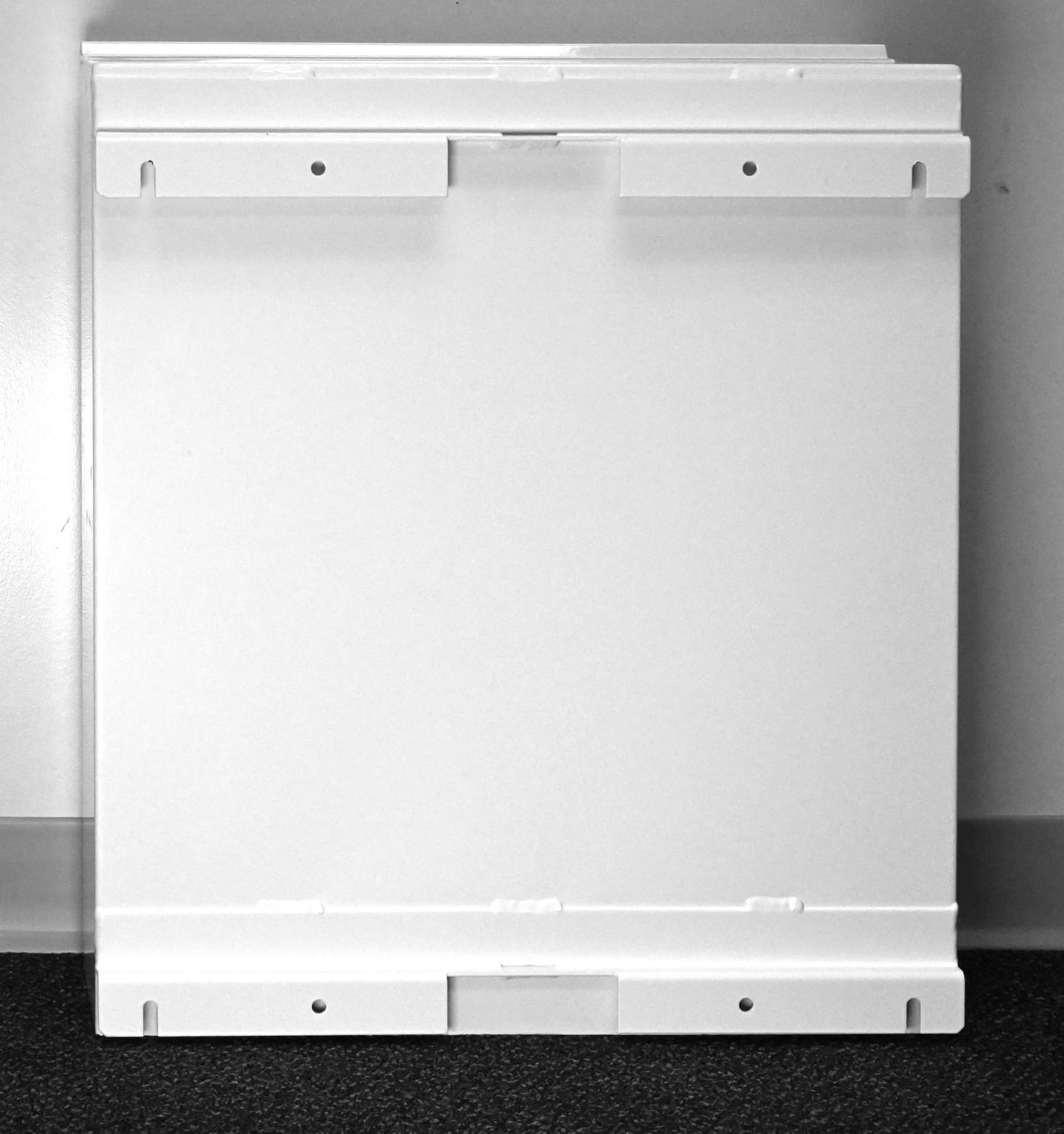
Click to zoom
Application Details
- Equipment Class
- TNB - Licensed Non-Broadcast Station Transmitter
- Date of Grant
- Apr 19, 2022
- Application Purpose
- Original Equipment
- Date of Application
- Apr 18, 2022
- Equipment Note
- Oceanographic High Frequency Doppler Radar
- Frequency Range
- 26.20000000 - 26.42000000
- Company
- University of Hawaii
- Country
- United States
Documents & Files
Document Text
Text extracted from the exhibit documents filed with the FCC. Open a document above to read the original.
Users Manual
University of Hawai'i at Mānoa School of Ocean and Earth Science and Technology Radio Oceanography Laboratory Generic High Frequency Doppler Radar Synthesizer-Transmitter Unit Model MK3-PW-PA-TX User Manual April 2022 v. 2 [email protected] Marine Sciences Building 1000 Pope road Honolulu Hawai'i 96822 FCC Supplier’s Declaration of Conformity University of Hawai'i Generic High Frequency Doppler Radar Synthesizer-Transmitter Unit, model MK3-PW-PA-TX. This device complies with part 15 of the FCC Rules. Operation is subject to the following two conditions: (1) this device may not cause harmful interference, and (2) this device must accept any interference received, including interference that may cause undesired operation. Changes or modifications not expressly approved by University of Hawai'i could void the user's authority to operate the equipment. University of Hawai'i at Mānoa School of Ocean and Earth Science and Technology Radio Oceanography Laboratory [email protected] 1000 Pope road Honolulu, HI 96822, U.S.A Phone (808) 956 7098 Warnings This device contains potentially dangerous high voltages and high frequency radiation. Operation and servicing is restricted to properly trained and certified personnel. Maximum output power is 50 W (+0.5dB) for frequencies 8 MHz and below and 30 W (+0.5dB) for frequencies 12 MHz and above. The user’s authority to operate this device if connected to any radiating antenna or structure in the United States is contingent on applying for and being awarded a valid license through the FCC Universal Licensing System before transmitting. This device may not be powered up for testing unless connected to a non-radiating resistive load. 2 Table of Contents User operation of Synthesizer-Transmitter Unit, model MK3-PW-PA-TX................................4 1. Overview.........................................................................................................................4 2. Start-up procedure..........................................................................................................5 3. Toggling between signal types........................................................................................5 4. Power-down procedure....................................................................................................6 5. Illustrations......................................................................................................................8 3 User operation of Synthesizer-Transmitter Unit, model MK3-PW-PA-TX 1. Overview The unit is programmed to emit a repetition of frequency sweeps (chirps), typically at a rate of 1Hz to 4Hz and an occupied bandwidth of 25 to 220kHz determined by the ITU frequency allocation (see Table 1), resulting in a frequency-modulated continuous wave (FMCW mode, emission designation F1N). Table 1. Allocation for Oceanographic High Frequency Doppler radars in Region 2. Center Occupied bandwidth (MHz)(kHz) 4.463 50 5.262525 13.500100 16.150100 24.550200 26.310220 The unit is factory-programmed to start transmitting automatically upon power up at the ITU frequency for which a low-pass filter is factory-fitted. To avoid any erroneous operation that could damage the power amplifier and/or the low-pass filter, or result in unlicensed transmissions, all frequencies are factory-disabled, except the ITU frequency for which a low-pass filter is actually factory-fitted to the unit. Programming the unit to other frequencies is password-protected and reserved to factory-authorized personnel. If a FCC call sign has been provided at the time of factory-configuration, a full-bandwidth broadcast of the call sign is automatically scheduled every 20 min. Chirps at a rate of 1 kHz are transmitted over the same occupied bandwidth, for short periods corresponding to the dots and dashes of the Morse code, resulting in a similar frequency-modulated continuous wave (emission designation F1N). The unit can be powered-up in two modes of operation: (a) a test mode, for which the output is connected to a 50Ω non-radiating resistive load, or (b), a live mode, for which the output is connected to a radiating antenna or structure. The user’s authority to operate this device in the live mode (b) from a location within the United States is contingent on being awarded a license through the FCC Universal Licensing System. In the absence of a valid FCC license, the device may only be operated in the test mode (a). The firmware allows programming all operations of the digital synthesizer, including chirping, calibration tones and full-bandwidth call-sign broadcast, using a single ethernet web server interface, configured through the Dynamic Host Configuration Protocol (DHCP; Figure 2). The actual settings of the digital synthesizers are continuously read back from the DDS registers and displayed on a separate diagnostic web page (Figure 3). 4 To comply with FCC RF exposure requirements, the antennas must be installed to ensure a minimum separation distance from persons while operational as shown in the table below: Table 2. Minimum separation to comply with FCC RF exposure requirements Operating Frequency Minimum Separation Distance (MHz)(m) 4.463 10.66 5.262510.66 13.5003.55 16.1503.55 24.5502.30 26.3102.30 2. Start-up procedure The following steps must be performed in the order given: 1.open enclosure and verify that the frequency of the low-pass filter fitted (figure 4) corresponds to the factory-configured frequency marked on the label (figure 3). 2.verify that all breakers are off in the down positions (figure 4). 3.for mode (a), connect a power attenuator such as a a Bird 100-SA-FFN-30 to the N-type RF output of the unit (figure 6). 4.for mode (b), connect the cable to the TX antenna, with a minimum cable attenuation of 5 dB (figure 6). 5.connect a CAT-6e cable from a local network to the RJ45 jack of the unit (figure 6). 6.connect a grounded power cable to the IEC-C13/C14 power inlet (figure 6) and plug i…
Text truncated - open the document above for the full version.
Attestation Statements
University of Hawaiʻi at Mānoa School of Ocean and Earth Science and Technology Department of Oceanography Radio Oceanography Laboratory 1000 Pope road Honolulu, Hawai’i 96822 Date: 3/21/2022 Attn: FCC Office of Engineering and Technology / UL Verification Services TCB Subject: Limiting of Sales to Customers Aware of Licensing Requirements To Whom It May Concern: This letter is provided to explain that the Radio Oceanography Laboratory of the University of Hawaiʻi at Mānoa limits the sales of its Generic Oceanographic High Frequency Doppler Radar system (G-HFDR, FCC ID: 2A562-MK3-PW-PA-TX), to non-commercial customers who understand that by operating such system, they are performing measurements of distance, direction and speed of ocean currents and waves by means of radio-location. Before being delivered such a system, customers must demonstrate competence in radio and radar technology by participating in a training workshop organized by the Radio Oceanography Laboratory of the University of Hawaiʻi at Mānoa. Customers must also certify that they will apply for a license through the FCC Universal Licensing System and that they understand that their authority to transmit through any radiating antenna or structure is contingent on their license have been awarded. Pierre Flament, Ph.D. [email protected] Principal Investigator Radio Oceanography Laboratory
Cover Letter(s)
University of Hawaiʻi at Mānoa School of Ocean and Earth Science and Technology Department of Oceanography Radio Oceanography Laboratory 1000 Pope road Honolulu, Hawai’i 96822 Date: 3/21/2022 UL Verification Services Inc. 47173 Benicia Street Fremont, CA 94538, USA To whom it may concern: I, the undersigned, hereby authorize UL Verification Services Inc. to act on our behalf in all manners relating to application for equipment authorization, including signing of all documents relating to these matters. Any and all acts carried out by UL Verification Services Inc. on our behalf shall have the same effect as acts of our own. I, the undersigned, hereby certify that we are not subject to a denial of federal benefits, that includes FCC benefits, pursuant to Section 5301 of the Anti-Drug Abuse Act of 1988, 21 U.S.C. 853(a). In authorizing UL Verification Services Inc. as our representative, we still recognize that we are responsible to: a. fulfill the requirements for the scope of certification requested, including implementing any appropriate changes requested by UL Verification Services Telecommunications Certification Body (TCB) and / or the FCC; b. supply any and all information needed for the evaluation of the products for which certification is sought; c. make claims regarding certification only in respect of the scope for which certification has been granted; d. not use our product certification in such a manner as to bring the TCB or FCC into disrepute and to not make any statement regarding product certification which the TCB or FCC may consider misleading or unauthorized; e. discontinue use of all advertising matter that contains any reference thereto and complies with any and all actions required by the FCC upon suspension or cancellation of certification; f. use certification only to indicate that products are certified in conformity with specified standards; g. endeavor to ensure that no certificate or report or any part thereof is used in a misleading manner, and any copies of the grants/certificates shall be reproduced in their entirety; h. comply with the requirements of the TCB and FCC, including the use of marks and label information prescribed for the scope of certification, when making reference to product certification in communication media such as documents, brochure or advertisements; i. comply with the requirements for certification, supply any information needed for evaluation of products to be certified and, where applicable, make provision for the participation of observers; j. ensure that products marketed under the scope of the requested certification continue to comply with the certification requirements; k. provide a sample of a production unit for testing within 30 days of the request should this product be selected as part of either the TCB’s or the FCC’s market surveillance requirements; l. keep a record of all complaints relating to product’s compliance with requirements of relevant standard; make records available to UL or FCC when requested; take appropriate action with respect to such complaints and any deficiencies found in the product that affect compliance with requirements for certification; document the actions taken with respect to complaints and/or deficiencies; m. inform the TCB immediately of any changes that may affect its ability to comply with the certification requirements. This authorization is valid until further written notice from the applicant. Pierre Flament, Ph.D. [email protected] Principal Investigator Radio Oceanography Laboratory
External Photos
External photos of Synthesizer-Transmitter Unit, model MK3-PW-PA-TX. Figure 1. Above: High Frequency Doppler Radar Synthesizer-Transmitter Unit model MK3-PW-PA- TX, serial 3-003, door closed. Below: device identification label, affixed to the top right of the enclosure door. The factory-programmed operating frequency and output power are marked, here for example 16.150 MHz/30W. 1 Figure 2. Synthesizer-Transmitter Unit, left and right side views. The twin-fan forced air flow heat exchanger unit is seen on the right side. Figure 3. Synthesizer-Transmitter Unit, bottom view. Connector plate with IEC-C13/C14 power inlet, RJ45 inlet for CAT6 ethernet, N-type bulkhead adapter for cable to antenna (a Bird 100-SA-FFN-30 power attenuator is attached). 2 Fig. 4. Synthesizer-Transmitter Unit, top view. The twin-fan forced air flow heat exchanger unit is seen on the right side. Fig. 5. Synthesizer-Transmitter Unit, back view (after removing unit from wall supports). 3
ID Label/Location Info
Proposed FCC ID label and location for Synthesizer-Transmitter Unit, model MK3-PW-PA-TX. Label Label Location The device identification label, affixed to the top right of the enclosure door.
Internal Photos
Internal photos of Synthesizer-Transmitter Unit, model MK3-PW-PA-TX. Figure 1. Synthesizer-Transmitter Unit, door open. Bottom rails: power supplies with circuit breakers. Upper rail: digital synthesizer and controller processor with blue thermal bell. 1 On the right wall: the power amplifier module and the low-pass filter. Figure 2. Synthesizer-Transmitter Unit, door open, slanted view. The power amplifier module (top) and the low-pass filter (bottom) are seen on the right inner wall. 2 Figure 3. Upper rail enlarged from Figure 1 and 2, after removal of the aluminum lid and thermal bell, showing the Triple DDS Radar Controller board. Figure 4. Bottom face of the Triple DDS Radar Controller board. Figure 5. Carrier board with FPGA, after removal of the Triple DDS Radar Controller board (top face; bottom face not accessible). 3
Operational Description
University of Hawai'i at Mānoa School of Ocean and Earth Science and Technology Radio Oceanography Laboratory Generic High Frequency Doppler Radar Synthesizer-Transmitter Unit Model MK3-PW-PA-TX Operational Description April 2022 v. 10 [email protected] Marine Sciences Building 1000 Pope road Honolulu Hawai'i 96822 FCC Supplier’s Declaration of Conformity University of Hawai'i Generic High Frequency Doppler Radar Synthesizer-Transmitter Unit, model MK3-PW-PA-TX. This device complies with part 15 of the FCC Rules. Operation is subject to the following two conditions: (1) this device may not cause harmful interference, and (2) this device must accept any interference received, including interference that may cause undesired operation. Changes or modifications not expressly approved by University of Hawai'i could void the user's authority to operate the equipment. University of Hawai'i at Mānoa School of Ocean and Earth Science and Technology Radio Oceanography Laboratory [email protected] 1000 Pope road Honolulu, HI 96822, U.S.A Phone (808) 956 7098 Warnings This device contains potentially dangerous high voltages and high frequency radiation. Operation and servicing is restricted to properly trained and certified personnel. Maximum output power is 50 W (+0.5dB) for frequencies 8 MHz and below and 30 W (+0.5dB) for frequencies 12 MHz and above. The user’s authority to operate this device if connected to any radiating antenna or structure in the United States is contingent on applying for and being awarded a valid license through the FCC Universal Licensing System before transmitting. This device may not be powered up for testing unless connected to a non-radiating resistive load. 2 Table of Contents Generic High Frequency Doppler Radar (G-HFDR)...................................................4 1. Physical principles................................................................................................4 2. System description and schematics.....................................................................5 3. Summary of specifications.................................................................................10 4. Tune-up procedure.............................................................................................10 5. Configuration and operation..............................................................................11 5.1. Start-up procedure..........................................................................................11 5.2. Toggling between signal types........................................................................12 5.3. Power-down procedure....................................................................................12 6. Antenna design..................................................................................................14 7. Photos of unit.....................................................................................................17 3 Generic High Frequency Doppler Radar (G-HFDR) 1. Physical principles The G-HFDR is an Oceanographic High Frequency Doppler radar designed with bare minimum features to ensure low production cost, low power requirement, and easy maintenance. The operation of the G-HFDR consists of transmitting frequency-modulated continuous radio waves that are channeled along the surface of the conducting ocean as ground waves, in the wavelength range of 10 to 100 m (frequency 3 to 30 MHz). These radio waves are coherently back-scattered by the ocean’s surface gravity waves at half the radio wavelength (5 to 50 m), and captured by an array of receive antennas. The back- scattered radio waves are shifted in frequency by the Doppler effect due to the sum of the surface wave velocities and the surface current. The velocity of the radial currents in the direction of the G-HFDR is estimated from this Doppler shift. For “Region 2”, the Americas, the International Telecommunication Union (ITU) has recommended and the Federal Communication Commission has allocated dedicated secondary frequency bands for operating High Frequency Doppler radars (Table 1). Table 1. Allocation for Oceanographic High Frequency Doppler radars in Region 2. Center Occupied bandwidth (MHz)(kHz) 4.463 50 5.262525 13.500100 16.150100 24.550200 26.310220 The G-HFDR consists of two units or subsystems: the Synthesizer-Transmitter Unit, and an optional Receiver-Digitizer Unit. The Synthesizer-Transmitter Unit is based on commercial off-the-shelf modules and contains: (i) an ultra-low phase noise reference oscillator (OCXO), (ii) direct digital signal synthesizers (DDS-FPGA), (iii) a power amplifier (PA), (iv) an anti-harmonic filter (LPF), (v) power supplies (PS) and power line filters (RFI). This unit is the subject of the present technical document. The optional Receiver-Digitizer Unit is based on schematics and engineering drawings published by the Radio Oceanography Laboratory and released in the public domain as Open Design/Open Source. It is a passive homodyne quadrature demodulator to baseband and does not contain any oscillator, frequency synthesizer or RF power amplifier. This unit is the subject of a separate technical document. The units exchange information with the outside world through ethernet links. Absolute timing, if required, can be provided by the precision network time protocol (ptp), encompassing master network-based GPS clocks or atomic clocks. 4 2. System description and schematics The following modules are integrated to form the Synthesizer-Transmitter Unit (Figure 1): 1. an ultra-low phase noise oven-controlled crystal oscillator (OCXO) fitted with a thermal- inertia bell, providing the clock signal to the digital synthesizer. Features: 100 MHz frequency, single side-band phase noise -148dBc/Hz. Manufacturer: Bliley (United States), model N79A- optA. The technical specification are found in appendix 1. 2. a clock-remapping direct digital synthesizer (DDS-C) to correct for frequency offset, ag…
Text truncated - open the document above for the full version.
Parts List/Tune Up Info
Tune-up procedure of Synthesizer-Transmitter Unit, model MK3-PW-PA-TX This device has no adjustments to tune output power and adjust reference frequency because these are digitally programmed during the manufacture of the system and drifts are non- existent within the precision of measurements. Programming the unit is password-protected and reserved to factory-authorized personnel. There are no user-accessible controls to modify the programming of the unit. Device identification label The operating frequency and output power which have been factory-programmed are marked. The label is affixed to the top right of the enclosure door. Example for 16.150 MHz.
RF Exposure Info
RF Exposure – Justification for Exemption from Routine Evaluation The minimum separation distance, R (m), to qualify for exemption from routine evaluation for rf exposure as detailed in 1.1307 Table 1 (version of April 2021) must be at least λ/2π, where λ is the free- space operating wavelength in meters. TABLE 1 TO §1.1307(b)(3)(i)(C) RF Source frequency (MHz) Threshold ERP (watts) 0.3-1.34 1,920 R 2 1.34-30 3,450 R 2 /f. 30-300 3.83 R 2 300-1,500 0.0128 R 2 f 1,500-100,000 19.2 R 2 Using the formulas from table 1 the power thresholds at the separation distances specified for the different operating frequencies for this series of devices are: Calculations to determine ERP thresholds above which routine evaluation for RF exposure would be required. Refer to 1.1307 Table 1 for formula. f (MHz) λ/2π (m) R = Separation Distance * 1 (m) ERP Power threshold (W) at distance R (m) Output Power (dBm) * 2 Ant Gain + Cable Loss (dBi) * 3 ERP (W) * 3 % of Threshold 4.48 10.66 10.66 19525 47.5 -3 17.2 0% 5.25 9.09 14224 47.5 -3 17.2 0% 13.45 3.55 3.55 240 45.5 -3 10.8 5% 16.10 2.97 168 45.5 -3 10.8 6% 24.45 1.95 2.30 31 45.5 -3 10.8 35% 26.20 1.82 27 45.5 -3 10.8 40% * 1 The minimum separation distance to qualify for exemption from routine evaluation for rf exposure as detailed in 1.1307 Table 1 must be at least λ/2π, where λ is the free-space operating wavelength in meters. * 2 The declared peak conducted output power at the port for this system is 50 W (47 dBm) for 10 MHz and below, and 30 W (45 dBm) for 10 MHz and above, with production tolerance of +0.5 dB. * 3 Declared by manufacturer, a maximum gain of 2 dBi normal-mode helical monopole antenna over finite ground plane and a minimum of 5 dB cable loss of RG213 or RG214 between the RF output and the antenna are used. EIRP (dBm) = P (dBm) + Ant Gain (dBi) – Cable Loss (dB) ERP (dBm) = EIRP (dBm) - 2.15 dB The ERP for all bands is below the threshold that would require routine evaluation and therefore the system is exempt from routine evaluation when installed with the minimum separation distances detailed in the installation instructions.
Schematics
Schematics of Synthesizer-Transmitter Unit, model MK3-PW-PA-TX The Synthesizer-Transmitter Unit is based on commercial off-the-shelf modules and contains: (i) an ultra-low phase noise reference oscillator (OCXO), (ii) direct digital signal synthesizers and controller (DDS-FPGA), (iii) a power amplifier (PA), (iv) an anti-harmonic filter (LPF), (v) power supplies (PS) and (vi) power line filters (RFI). A detailed description of the modules is provided in companion technical report “Generic High Frequency Doppler Radar Synthesizer-Transmitter Unit: Operational Description”, April 2022 issued by the Radio Oceanography Laboratory of the University of Hawai'i at Mānoa. Figure 1. Schematics of the Synthesizer-Transmitter Unit. See Table 1 for list of components and references. 1 Figure 2. Schematics of the Triple DDS Radar Controller. See Table 2 for list of components and references. Figure 3. Photo of the Triple DDS Radar Controller board. 2 SXLP-30+ Filter Driver SXLP-30+ Filter Driver AD9512 Secondary Clock Buffer / Divider IOUD/BPSK / OSK AD9854 DDS A SXLP-30+ Filter Driver SXLP-30+ Filter Driver OCXO SXLP-30+ Filter AD9854 DDS C Clock Remap AD9854 DDS B AD9512 Primary Clock Buffer / Divider CLK IN SPI SPI I OUT Q OUT I OUT Q OUT SPI IOUD/BPSK / OSK MCX Cable Connector Logic Connection with FPGA KEY Table 1. List of commercial modules incorporated in the Synthesizer-Transmitter Unit TagDescriptionReferenceManufacturer OCXOOven-controlled crystal oscillator, 100 MHz N79A-optABliley Technologies Inc. 2545 W Grandview Blvd, Erie PA 16506 USA FPGACarrier with embedded FPGA&ARM processors ACQ1001D-TACQ Solutions Ltd., International House Stanley Blvd, Blantyre G72 0BN Scotland UK DDSTriple DDS Radar Controller RAD-CELFid. PARadio-frequency power amplifier BTM00250-AlphaSATomco Technologies 38 Payneham Rd, Stepney, Australia 5069 LPFPower low-pass filterFLxxMLP-HFDRDLW Associates 6 Woodford place, St. Charles MO 63301 USA PS12VIndustrial power supplyTSP-070–112Traco Electronic AG Sihlbruggstrasse 111, CH-6340 Baar PS26VIndustrial power supplyTSP-360–124id. RFI-DCEMI Filter with High Attenuation Performance FN2030M-Z-20-06Schaffner Holding AG Nordstrasse 11, CH-4542 Luterbach RFI-ACEMI Filter with High Attenuation Performance FN9266-10-06id. Table 2. List of functional integrated circuits used in the Triple DDS Radar Controller TagDescriptionReferenceManufacturer PrimaryClock/buffer dividerAD9512BCPZAnalog Devices One Analog Way, Wilmington MA 01887 USA SecondaryClock/buffer dividerAD9512BCPZid. DDS-ADirect digital synthesizer AD9854ASVZid. DDS-BDirect digital synthesizer AD9854ASVZid. DDS-CDirect digital synthesizer AD9854ASVZid. FilterLumped LC low-pass filter SXLP-27+Mini-Ciruits 13 Neptune Ave, Brooklyn NY 11235 USA DriverOperational amplifierOPA2694DTexas Instruments 12500 TI Blvd., Dallas TX 75243 USA Note: other commodity components (inductors, capacitors, resistors, voltage regulators) used on the Triple DDS Radar signal synthesizer board have passive functions and do not contribute to the signal generation. 3
Test Report
CERTIFICATION TEST REPORT Report Number : 14236793-E1V3 Applicant : UNIVERSITY OF HAWAII 1000 POPE ROAD, MSB 402, HONOLULU, HI 96822, U.S.A. Model : MK3-PW-PA-TX FCC ID : 2A562-MK3-PW-PA-TX EUT Description : OCEANOGRAPHIC HIGH FREQUENCY DOPPLER RADAR Test Standard : FCC CFR 47 PART 90 SUBPART F Date Of Issue: April 19, 2022 Prepared by: UL Verification Services Inc. 47173 Benicia Street Fremont, CA 94538, U.S.A. TEL: (510) 319-4000 FAX: (510) 661-0888 REPORT NO: 14236793-E1V3 DATE: APRIL 19, 2022 MODEL: MK3-PW-PA-TX FCC ID: 2A562-MK3-PW-PA-TX Page 2 of 41 UL VERIFICATION SERVICES INC 47173 BENICIA STREET, FREMONT, CA 94538, USA TEL: (510) 319-4000 FAX: (510) 661-0888 This report shall not be reproduced except in full, without the written approval of UL Verification Services Inc. Revision History Rev. Issue Date Revisions Revised By V1 04/11/22 Initial Issue GP Chin V2 04/14/22 Updated Description of EUT in Section 5.1 Updated Power Summary Table in Section 5.3 Added Notes on Pg. 32 and Pg. 35 GP Chin V3 04/19/22 Added Note on Pg. 17 in Section 8.3. GP Chin REPORT NO: 14236793-E1V3 DATE: APRIL 19, 2022 MODEL: MK3-PW-PA-TX FCC ID: 2A562-MK3-PW-PA-TX Page 3 of 41 UL VERIFICATION SERVICES INC 47173 BENICIA STREET, FREMONT, CA 94538, USA TEL: (510) 319-4000 FAX: (510) 661-0888 This report shall not be reproduced except in full, without the written approval of UL Verification Services Inc. TABLE OF CONTENTS 1. ATTESTATION OF TEST RESULTS .................................................................................... 4 2. TEST METHODOLOGY ........................................................................................................ 5 3. FACILITIES AND ACCREDITATION .................................................................................... 5 4. CALIBRATION AND UNCERTAINTY .................................................................................. 6 4.1. METROLOGICAL TRACEABILITY ................................................................................ 6 4.2. DECISION RULES ......................................................................................................... 6 4.3. MEASUREMENT UNCERTAINTY ................................................................................. 6 5. EQUIPMENT UNDER TEST ................................................................................................. 7 5.1. DESCRIPTION OF EUT ................................................................................................. 7 5.2. DESCRIPTION OF AVAILABLE ANTENNAS ................................................................ 7 5.3. MAXIMUM OUTPUT POWER ........................................................................................ 8 5.4. SOFTWARE AND FIRMWARE ...................................................................................... 8 6. DESCRIPTION OF TEST SETUP ......................................................................................... 9 7. TEST AND MEASUREMENT EQUIPMENT ....................................................................... 12 8. APPLICABLE LIMITS AND TEST RESULTS .................................................................... 13 8.1. DUTY CYCLE ............................................................................................................... 13 8.2. OCCUPIED BANDWIDTH ............................................................................................ 15 8.3. PEAK OUTPUT POWER .............................................................................................. 17 8.4. FREQUENCY STABILITY ............................................................................................ 19 8.5. TX CONDUCTED SPURIOUS EMISSIONS AND BAND EDGE .................................. 22 8.5.1. SPURIOUS EMISSIONS ....................................................................................... 24 8.5.2. BAND EDGE ......................................................................................................... 28 8.6. TX RADIATED SPURIOUS EMISSIONS ..................................................................... 30 9. SETUP PHOTOS ................................................................................................................. 38 REPORT NO: 14236793-E1V3 DATE: APRIL 19, 2022 MODEL: MK3-PW-PA-TX FCC ID: 2A562-MK3-PW-PA-TX Page 4 of 41 UL VERIFICATION SERVICES INC 47173 BENICIA STREET, FREMONT, CA 94538, USA TEL: (510) 319-4000 FAX: (510) 661-0888 This report shall not be reproduced except in full, without the written approval of UL Verification Services Inc. 1. ATTESTATION OF TEST RESULTS COMPANY NAME: UNIVERSITY OF HAWAII 1000 POPE ROAD, MSB 402, HONOLULU, HI 96822, U.S.A. EUT DESCRIPTION: OCEANOGRAPHIC HIGH FREQUENCY DOPPLER RADAR MODEL: MK3-PW-PA-TX SERIAL NUMBER: 3-003 DATE TESTED: MARCH 9 TH - 17 TH , 2022 APPLICABLE STANDARDS STANDARD TEST RESULTS FCC PART 90.103F Complies UL Verification Services Inc. tested the above equipment in accordance with the requirements set forth in the above standards. The test results show that the equipment tested is capable of demonstrating compliance with the requirements as documented in this report. The results documented in this report apply …
Text truncated - open the document above for the full version.
Contact Information
Applicant
Pierre Flament(Researcher)
Technical Contact
UL Verification Services Inc.Sol Kuwatani
[email protected]5107711000
47173 Benicia Street · Fremont, California · United States
Test Firm
UL Verification Services Inc.Jay Kogoma
[email protected]510 319 4135
Technical Specifications
| # | Rule Parts | Frequency Range | Power Output | Emission | Tolerance |
|---|---|---|---|---|---|
| 6 | 9 | 26.2 MHz - 26.42 MHz | 15.6 W | 211KF1N | 20 ppm |