2A58O-MBE001wireless on-ear speakers
NTT Sonority Inc.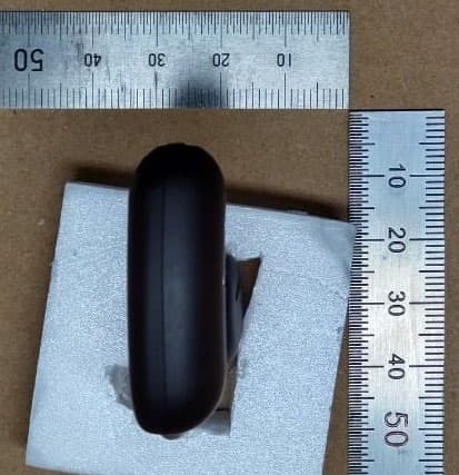
Click to zoom
Application Details
- Equipment Class
- DTS - Digital Transmission System
- Date of Grant
- Feb 15, 2023
- Application Purpose
- Original Equipment
- Date of Application
- Feb 15, 2023
- Equipment Note
- wireless on-ear speakers
- Frequency Range
- 2402.00000000 - 2480.00000000
- Company
- NTT Sonority Inc.
- Country
- Japan
Documents & Files
Document Text
Text extracted from the exhibit documents filed with the FCC. Open a document above to read the original.
Users Manual
Download the full warranty card and safety information and other helpful information from our website. wireless on-ear speakers Safety guide Class 1 Laser information This device is classified as a Class 1 Laser product per IEC 60825-1:2014. This device complies with 21 CFR 1040.10 and 1040.11, except for conformance with IEC 60825-1:2014, as described in Laser Notice No. 56, dated May 8, 2019. Caution: This device contains one or more lasers. Use other than as described in the manual, repair, or disassembly may cause damage, which could result in hazardous exposure to infrared laser emissions that are not visible. This equipment should be serviced by an authorized service provider. Thank you for buying this NTT sonority product. The precautions listed below are to prevent risk of harm to the user and others, as well as to prevent property damage, and to help the user use this unit properly and safety. Be sure to follow these instructions. After you have finished reading the instructions, put them away in a safe place for future reference. Leak-resistant construction This product has been manufactured in accord with the leak-resistant standard IPX2 * 1 established by the International Electrotechnical Commission (I EC), but it may be damaged if splashed with or immersed in water. *1 Water dripping vertically from a height of 200 mm at a rate equivalent to 3 mm rainfall/min shall have no harmful effect on the headphones performance when the enclosure is tilted at an angle up to 15° from its normal position in each axis. Test duration: 10 minutes (2.5 mins per axis direction). Other precautions Do not wash or rinse this product in water, since it may be damaged. These headphones have been designed to resist the entry of perspiration and water, but exposure to large amounts of liquid can result in damage due to leaking into the headphones. This unit is not designed to resist heat and humidity. As a result, do not use in a sauna, and do not use hair dryers or other heating devices to dry the unit. In cold regions or other cold places, there is a risk of freezing if moisture is left adhered. This could cause a failure, so be sure to wipe off any moisture after use. WARNING Adjust speaker sound to the proper volume. Loud sound may damage your ears. This unit should not be used by persons who have heart pacemakers installed, since adverse affects could occur. Do not use this unit in hospitals or clinics, or near medical equipment. To prevent a fire hazard, do not place any naked flame sources (such as a lighted candle) on the equipment. A warning not to expose the battery (battery pack or batteries installed) to excessive heat or cold such as direct sunlight or fire. Never inspect the inside OR remodel this machine. If the customer remodels this machine, NTT sonority will no longer guarantee its performance. If any itching or skin discomfort occurs during use, cease use immediately. CAUTION Precautions for use Subjecting the device to a strong force or impact may impair the appearance or performance of the device, resulting in malfunction or damage. The microphone may be damaged if sweat or moisture is allowed inside. Take particular care when using the earphones in conditions of rain, lightning, near the ocean, river, or lake. The ear cushion cannot be removed. Forcibly removing it will result in damage. If it is dirty, wipe the dirt off with a soft, dry cloth. When doing so, do not blow air into the speaker unit. Tail tips may degrade over long periods of use or storage. In this event consult your dealer. In very dry environments, static electricity accumulated in the human body may cause tiny shocks to be felt at the ears. This product is not edible. Place out of reach of small children to prevent accidental ingestion of small parts. Disconnect the charging cable from carrying case before storing the earphones in a bag or the like. Leaving the charging terminal parts in a dirt state may cause a contact failure, malfunction, or fire. Furthermore, allowing metal to contact the terminal parts may cause a malfunction or fire. Wipe them occasionally with a soft cloth to keep them clean. Be careful when opening and closing the carrying case as there is a risk of trapping a finger, etc. In particular, be sufficiently careful when it is handled by a small child. If the carrying case is opened during charging, the cord will be pulled, which may result in a broken wire or malfunction. Make sure you disconnect the cord before opening the carrying case. The Safety of Your Ears is in Your Hands Get the most out of your equipment by playing it at a safe level – a level that lets the sound come through clearly without annoying blaring or distortion and, most importantly, without affecting your sensitive hearing. Sound can be deceiving. Over time, your hearing “comfort level” adapts to higher volumes of sound, so what sounds “normal” can actually be loud and harmful to your hearing. Guard against this by setting your equipment at a safe level BEFORE your hearing adapts. ESTABLISH A SAFE LEVEL: Set your volume control at a low setting. Slowly increase the sound until you can hear it comfortably and clearly, without distortion. Once you have established a comfortable sound level, set the dial and leave it there. BE SURE TO OBSERVE THE FOLLOWING GUIDELINES: Do not turn up the volume so high that you can ’t hear what’s around you. Use caution or temporarily discontinue use in potentially hazardous situations. Do not use headphones while operating a motorized vehicle; the use of headphones may create a traffic hazard and is illegal in many areas. Note Internal Rechargeable Lithium-ion Battery This device uses an internal rechargeable lithium-ion battery that should last the lifetime of the device. If you suspect your battery may be dead, try charging it several times. If the battery does not recharge, please contact us for repair information. Operating Environment Operating environment temperature and humidity: …
Text truncated - open the document above for the full version.
Attestation Statements
Around The World Trading, Inc 7636 Miramar Road, Suite 1300, San Diego CA 92126 TEL: (858) 715-0461 CFR 47 §2.911 (d)(7) FCC US Agent Letter of Attestation Date: May 22, 2023 FCC ID: 2A58O-MBE001 Grantee FRN: 0032216616 To: Federal Communications Commission 45 L Street NE Washington, DC 20554 USA FCC US Agent Around The World Trading Inc FRN: 0026277541 Aki Nagai 7636 Miramar Rd. #1300, San Diego, CA 92126, U.S.A. [email protected] This letter is to confirm that we have accepted the responsibility to act as US Agent on behalf of NTT Sonority Inc. (“the applicant”) for the above referenced FCC ID. We are aware of the requirements and responsibilities of the applicant’s agent for service of process as outlined in the FCC section 2.911(d)(7) and Report and Order FCC 22-84 paragraph 63. Sincerely yours, Aki Nagai CEO Around The World Trading Inc
External Photos
MBE001Appearance photo DSGNCHKAPVD S.SakuraiS.MoritaK.Suzuki 12/26/2212/26/2212/26/22 Information contained in this document is PRIVILEGED and CONFIDENTIAL MBE001_Appearance photo 得意先名 Customer N85(NTT Sonority) 得意先モデル名 CustomerModelName MBE001 機種番号 FosterModelNumber 650596 変更履歴 版数発行日変更・改定内容作成承認 1. 0 2022/12/21 1st edition issued FSRGFSKK Information contained in this document is PRIVILEGED and CONFIDENTIAL APPEARACE PICTURE Lch FRONT VIEWREAR VIEW Information contained in this document is PRIVILEGED and CONFIDENTIAL APPEARACE PICTURE Lch SIDE VIEW (RIGHT)SIDE VIEW (LEFT) Information contained in this document is PRIVILEGED and CONFIDENTIAL APPEARACE PICTURE Lch TOP VIEWBOTTOM VIEW Information contained in this document is PRIVILEGED and CONFIDENTIAL APPEARACE PICTURE Rch FRONT VIEWREAR VIEW Information contained in this document is PRIVILEGED and CONFIDENTIAL APPEARACE PICTURE Rch SIDE VIEW (RIGHT)SIDE VIEW (LEFT) Information contained in this document is PRIVILEGED and CONFIDENTIAL APPEARACE PICTURE Rch TOP VIEWBOTTOM VIEW EOF
ID Label/Location Info
This product is too small to label FCC ID on it. Therefore FCC ID is placed on the user manual and the carrying case.
Internal Photos
MBE001Internal photo DSGNCHKAPVD S.SakuraiS.MoritaK.Suzuki 12/26/2212/26/2212/26/22 Information contained in this document is PRIVILEGED and CONFIDENTIAL MBE001_Internal photo 得意先名 Customer N85(NTT Sonority) 得意先モデル名 CustomerModelName MBE001 機種番号 FosterModelNumber 650596 変更履歴 版数発行日変更・改定内容作成承認 1.0 2022/12/26 1st edition issued FSRGFSKK Information contained in this document is PRIVILEGED and CONFIDENTIAL Internal photo MAINPWB Lch(RF module PWB) BT IC Side ASide B Information contained in this document is PRIVILEGED and CONFIDENTIAL Internal photo ANTENNAPWB Lch ANTENNA Side A Side B Information contained in this document is PRIVILEGED and CONFIDENTIAL Internal photo FPCPWB Lch Side ASide B Information contained in this document is PRIVILEGED and CONFIDENTIAL Internal photo RF module PWB position Lch ANTENNA Information contained in this document is PRIVILEGED and CONFIDENTIAL Internal photo RF module PWB position Lch ANTENNA Information contained in this document is PRIVILEGED and CONFIDENTIAL Internal photo RF module PWB position Lch ANTENNA Main FPC Information contained in this document is PRIVILEGED and CONFIDENTIAL Internal photo MAINPWB Rch(RF module PWB) BT IC Side A Side B Information contained in this document is PRIVILEGED and CONFIDENTIAL Internal photo ANTENNAPWB Rch ANTENNA Side A Side B Information contained in this document is PRIVILEGED and CONFIDENTIAL Internal photo FPCPWB Rch Side A Side B Information contained in this document is PRIVILEGED and CONFIDENTIAL Internal photo RF module PWB position Rch ANTENNA Information contained in this document is PRIVILEGED and CONFIDENTIAL Internal photo RF module PWB position Rch ANTENNA Information contained in this document is PRIVILEGED and CONFIDENTIAL Internal photo RF module PWB position Rch ANTENNA Main FPC EOF
RF Exposure Info
UL Japan, Inc. Shonan EMC Lab. 1-22-3 Megumigaoka, Hiratsuka-shi, Kanagawa-ken, 259-1220 Japan / +81-463-50-6400 2023/1/20 FCC ID: 2A58O-MBE001 To whom it may concern, We, UL Japan, Inc., hereby declare that wireless on-ear speakers, model : MBE001 (FCC ID: 2A58O-MBE001) of NTT Sonority Inc. is exempt from RF exposure SAR evaluation with RF Exposure Compliance requirements of the KDB 447498 D01 General RF Exposure Guidance. (It is necessary to comply of FCC section 2.1093 in reality, however, it is exempted by KDB 447498 D01.) KDB 447498 D01 has the following exclusion for portable devices: The 1g and 10g SAR test exclusion thresholds for 100 MHz to 6 GHz at test separation distances < 50 mm are determined by: [(measured maximum average output power(mW))/(Minimum separation distance(mm))]•[ √ f (GHz)] < 3.0 for 1g SAR and < 7.5 for 10g extremity SAR where • f(GHz) is the RF channel transmit frequency in GHz • Power and distance are rounded to the nearest mW and mm before calculation • The result is rounded to one decimal place for comparison The test exclusions are applicable only when the minimum test separation distance is < 50 mm and for transmission frequencies between 100 MHz and 6 GHz. When the minimum test separation distance is < 5 mm, a distance of 5 mm is applied to determine SAR test exclusion. This device f = 2.48 GHz, distance = 5 mm (minimum separation distance: 5 mm was used in the calculation) and the measured maximum average output power was 4 mW and 5 mW So for this device: Bluetooth (BR / EDR): 4 mW [measured maximum average output power] / 5 mm [minimum separation distance] * ( √ 2.48) = 1.3 Bluetooth Low Energy: 5 mW [measured maximum average output power] / 5 mm [minimum separation distance] * ( √ 2.48) = 1.6 *This is less than 3.0, so no SAR is required. Even taking into account the tolerance, this device can be satisfied with the limits. Thank you for your attention to this matter. Toyokazu Imamura Leader UL Japan, Inc.
Test Report
MBE001AntennaSpecification DSGNCHKAPVD S.SakuraiJ.ParkY.Hibino Feb/09/23Feb/09/23Feb/09/23 Antenna Information Information contained in this document is privileged and confidential. 2 Confidential - Manufacturer:Foster Electric Company, Limited - H.Q. Address:1-1-109, Tsutsujigaoka, AkishimaCity, Tokyo, 196-8550, Japan - Model Name:MBE001 - Frequency Range:2402MHz~2480MHz - Antenna Type:Monopole Antenna(FPC pattern Antenna) - Connector Type:X.FL - Cable length : No cable - Cable Loss : -dB Antenna Information Information contained in this document is privileged and confidential. 3 Confidential - Antenna Gain: Lch-1.8dBi/ Rch-1.6dBi※Application value:below -1.6dBi ※Refer to p5~p10 - Test Date:9/29/2022 - Test PIC:SeigoSakurai/ Takahiko Ishikura - Instruments:Network analyzer E-5071C_Keysight (Latest Calibration date:12/16/2021) - Test System Name: ETS-LINDGREN EMQuestAntenna measurement site - Test Photo:Refer to p8、p10 Antenna Shape Information contained in this document is privileged and confidential. 4 Confidential Lch Rch Type:Monopole Antenna(FPCpattern antenna) Impedance:50Ω Element Pink :Silk Antenna Information Information contained in this document is privileged and confidential. 5 Confidential - ANT chamber Wiring Diagram Antenna Information Information contained in this document is privileged and confidential. 6 Confidential - Antenna Gain Measuring method (1)Fix the DUT on the foam head and perform passive radiation pattern (3D) measurements.※Refer to Figure 4 (2) A 2D (Z-X plane, Z-Y plane, X-Y plane) radiation pattern is obtained from a 3D radiation pattern.※Refer to Figure 5 Antenna Gain_Lch Information contained in this document is privileged and confidential. 7 Peak Gain:-1.805dBi Confidential Frequency(Channel)2402MHz(ch0)2441MHz(ch39)2480MHz(ch78) Peak gain(dBi)-2.599-1.977-1.805 Total power(dBm)-6.654-5.951-5.829 Efficiency(%)21.6125.4026.13 Peak Radiation pattern_Lch Information contained in this document is privileged and confidential. 8 Confidential Radiation pattern 2D (X-Y Plane) -5.10-4.12-3.68 Total Peak gain (dBi) -3.85-3.08-2.65 Center Frequency2402MHz2441MHz2480MHz Horizontal Peak gain (dBi)-9.37-9.03-9.00 Vertical Peak gain (dBi) -40.00 -35.00 -30.00 -25.00 -20.00 -15.00 -10.00 -5.00 0. 00 5. 00 0 15 30 45 60 75 90 105 120 135 150 165 180 195 210 225 240 255 270 285 300 315 330 345 2480MHz Horizontal Vertical Total Hor Peak Ver Peak Total Peak Z axis rotation angle vs gain(dBi) -40.00 -35.00 -30.00 -25.00 -20.00 -15.00 -10.00 -5.00 0. 00 5. 00 0 15 30 45 60 75 90 105 120 135 150 165 180 195 210 225 240 255 270 285 300 315 330 345 2441MHz Horizontal Vertical Total Z axis rotation angle vs gain(dBi) -40.00 -35.00 -30.00 -25.00 -20.00 -15.00 -10.00 -5.00 0. 00 5. 00 0 15 30 45 60 75 90 105 120 135 150 165 180 195 210 225 240 255 270 285 300 315 330 345 2402MHz Horizontal Vertical Total Hor Peak Ver Peak Total Peak Z axis rotation angle vs gain(dBi) Y X Radiation pattern 2D (Z-Y Plane) Vertical Peak gain (dBi)-7.49-6.95-6.93 Total Peak gain (dBi) -4.86 -4.47-4.85 Center Frequency 2402MHz 2441MHz2480MHz Horizontal Peak gain (dBi)-5.92-5.31-4.93 -40.00 -35.00 -30.00 -25.00 -20.00 -15.00 -10.00 -5.00 0. 00 5. 00 0 15 30 45 60 75 90 105 120 135 150 165 180 195 210 225 240 255 270 285 300 315 330 345 2402MHz Horizontal Vertical Total Hor Peak Ver Peak Total Peak X axis rotation angle vs gain(dBi) -40.00 -35.00 -30.00 -25.00 -20.00 -15.00 -10.00 -5.00 0. 00 5. 00 0 15 30 45 60 75 90 105 120 135 150 165 180 195 210 225 240 255 270 285 300 315 330 345 2441MHz Horizontal Vertical Total X axis rotation angle vs gain(dBi) -40.00 -35.00 -30.00 -25.00 -20.00 -15.00 -10.00 -5.00 0. 00 5. 00 0 15 30 45 60 75 90 105 120 135 150 165 180 195 210 225 240 255 270 285 300 315 330 345 2480MHz Horizontal Vertical Total Hor Peak Ver Peak Total Peak X axis rotation angle vs gain(dBi) Z Y Radiation pattern 2D (Z-X Plane) 21.625.426.1 File Name: 2022.09.29.18.30.14_Tesla TP1_Passive_Lch_Air_head_-6.65 -5.95 -5.83.raw Test MeFile Name: 2022.09.29.18.30.14_Tesla TP1_Passive_Lch_Air_head_-6.65 -5.95 -5.83.raw Test MeFile Name: 2022.09.29.18.30.14_Tesla TP1_Passive_Lch_Air_head_-6.65 -5.95 -5.83.raw Test Me Vertical Peak gain (dBi)-4.35-3.43-3.07 Total Peak gain (dBi)-2.60-1.98-1.80 Horizontal Peak gain (dBi)-5.92-5.71-5.69 Efficiency (dB) (%)-6.65-5.95-5.83 Center Frequency2402MHz2441MHz2480MHz -40.00 -35.00 -30.00 -25.00 -20.00 -15.00 -10.00 -5.00 0. 00 5. 00 0 15 30 45 60 75 90 105 120 135 150 165 180 195 210 225 240 255 270 285 300 315 330 345 2402MHz Horizontal Vertical Total Y axis rotation angle vs gain(dBi) -40.00 -35.00 -30.00 -25.00 -20.00 -15.00 -10.00 -5.00 0. 00 5. 00 0 15 30 45 60 75 90 105 120 135 150 165 180 195 210 225 240 255 270 285 300 315 330 345 2441MHz Horizontal Vertical Total Y axis rotation angle vs gain(dBi) -40.00 -35.00 -30.00 -25.00 -20.00 -15.00 -10.00 -5.00 0. 00 5. 00 0 15 30 45 60 75 90 105 120 135 150 165 180 195 210 225 240 255 270 285 300 315 330 345 2480MHz Horizontal Vertical Total Hor Peak Ver Peak Total Peak Y axis rotation angle vs gain(dBi) Passive radiation pattern DUT : Tester : E5071C Z X Antenna Gain_Rch Information contained in this document is privileged and confidential. 9 Peak Gain:-1.597dBi Confidential Frequency(Channel)2402MHz(ch0)2441MHz(ch39)2480MHz(ch78) Peak gain(dBi)-2.514-1.646-1.597 Total power(dBm)-6.520-5.693-5.733 Efficiency(%)22.2926.9626.71 Peak Radiation pattern_Rch Information contained in this document is privileged and confidential. 10 Confidential Radiation pattern 2D (X-Y Plane) -6.81 -6.14-5.70 Total Peak gain (dBi)-3.98-3.15-3.07 Center Frequency2402MHz2441MHz2480MHz Horizontal Peak gain (dBi) -7.13-6.18-6.31 Vertical Peak gain (dBi) -40.00 -35.00 -30.00 -25.00 -20.00 -15.00 -10.00 -5.00 0. 00 5. 00 0 15 30 45 60 75 90 105 120 135 150 165 180 195 210 225 240 255 270 285 300 315 330 345 2480MHz Horizontal Vertical Total Hor Peak Ver Peak Total Peak Z axis rotation angle vs gain(dBi) -40.00 -35.00 -30.00 -25.00 -20.00 -15…
Text truncated - open the document above for the full version.
Test Report
Test Report No. : 14597255S-H Page : 1 of 48 UL Japan, Inc. Shonan EMC Lab. 1-22-3 Megumigaoka, Hiratsuka-shi, Kanagawa-ken, 259-1220 Japan / +81-463-50-6400 RADIO TEST REPORT Test Report No. 14597255S-H Customer NTT Sonority Inc. Description of EUT wireless on-ear speakers Model Number of EUT MBE001 FCC ID 2A58O-MBE001 Test Regulation FCC Part 15 Subpart C Test Result Complied (Refer to SECTION 3) Issue Date January 20, 2023 Remarks Bluetooth Low Energy part(s) Representative Test Engineer Approved By Miku Ikudome Engineer Toyokazu Imamura Leader CERTIFICATE 1266.03 The testing in which "Non-accreditation" is displayed is outside the accreditation scopes in UL Japan, Inc. There is no testing item of "Non-accreditation". Report Cover Page - Form-ULID-003532 (DCS:13-EM-F0429) Issue# 21.0 Test Report No. : 14597255S-H Page : 2 of 48 UL Japan, Inc. Shonan EMC Lab. 1-22-3 Megumigaoka, Hiratsuka-shi, Kanagawa-ken, 259-1220 Japan / +81-463-50-6400 ANNOUNCEMENT REVISION HISTORY Original Test Report No.: 14597255S-H Revision Test Report No. Date Page Revised Contents - (Ori ginal) 14597255S-H January 20, 2023 - • This test report shall not be reproduced in full or partial, without the written approval of UL Japan, Inc. • The results in this report appl y only to the sample tested. (Laboratory was not involved in sampling.) • This sample tested is in compliance with the limits of the above re gulation. • The test results in this test report are traceable to the national or international standards. • This test report must not be used by the customer to claim product certification, approval, or endorsement by the A2LA accreditation bod y. • This test report covers Radio technical requirements. It does not cover administrative issues such as Manual or non-Radio test related Requirements. (if applicable) • The all test items in this test report are conducted b y UL Japan, Inc. Shonan EMC Lab. • The opinions and the interpretations to the result of the description in this report are outside scopes where UL Japan, Inc. has been accredited. • The information provided from the custome r for this report is identified in Section 1. • For test report(s) referred in this report, the latest version (includin g any revisions) is always referred. Test Report No. : 14597255S-H Page : 3 of 48 UL Japan, Inc. Shonan EMC Lab. 1-22-3 Megumigaoka, Hiratsuka-shi, Kanagawa-ken, 259-1220 Japan / +81-463-50-6400 Reference: Abbreviations (Including words undescribed in this report) A2LA The American Association for Laboratory Accreditation ICES Interference-Causing Equipment Standard AC Alternating Current IEC International Electrotechnical Commission AFH Adaptive Frequency Hopping IEEE Institute of Electrical and Electronics En gineers AM Amplitude Modulation IF Intermediate Frequency Amp, AMP Amplifier ILAC International Laboratory Accreditation Conference ANSI American National Standards Institute ISED Innovation, Science and Economic Develo pment Canada Ant, ANT Antenna ISO International Organization for Standardization AP Access Point JAB Japan Accreditation Board ASK Amplitude Shift Keying LAN Local Area Network Atten., ATT Attenuator LIMS Laboratory Information Management System AV Average MCS Modulation and Coding Scheme BPSK Binary Phase-Shift Keying MRA Mutual Recognition Arrangement BR Bluetooth Basic Rate N/A Not Applicable BT Bluetooth NIST National Institute of Standards and Technolo gy BT LE Bluetooth Low Energy NS No signal detect. BW BandWidth NSA Normalized Site Attenuation Cal Int Calibration Interval NVLAP National Voluntary Laboratory Accreditation Pro gram CCK Complementary Code Keying OBW Occupied Band Width Ch., CH Channel OFDM Orthogonal Frequency Division Multiplexing CISPR Comite International Special des Perturbations Radioelectriques P/M Power meter CW Continuous Wave PCB Printed Circuit Board DBPSK Differential BPSK PER Packet Error Rate DC Direct Current PHY Physical Layer D-factor Distance factor PK Peak DFS Dynamic Frequency Selection PN Pseudo random Noise DQPSK Differential QPSK PRBS Pseudo-Random Bit Sequence DSSS Direct Sequence Spread Spectrum PSD Power Spectral Density EDR Enhanced Data Rate QAM Quadrature Amplitude Modulation EIRP, e.i.r.p. Equivalent Isotropically Radiated Power QP Quasi-Peak EMC ElectroMagnetic Compatibility QPSK Quadri-Phase Shift Keying EMI ElectroMagnetic Interference RBW Resolution Band Width EN European Norm RDS Radio Data System ERP, e.r.p. Effective Radiated Power RE Radio Equipment EU European Union RF Radio Frequency EUT Equipment Under Test RMS Root Mean Square Fac. Factor RSS Radio Standards Specifications FCC Federal Communications Commission Rx Receiving FHSS Frequency Hopping Spread Spectrum SA, S/A Spectrum Analyzer FM Frequency Modulation SG Signal Generator Freq. Frequency SVSWR Site-Voltage Standing Wave Ratio FSK Frequency Shift Keying TR Test Receiver GFSK Gaussian Frequency-Shift Keying Tx Transmitting GNSS Global Navigation Satellite System VBW Video BandWidth GPS Global Positioning System Vert. Vertical Hori. Horizontal WLAN Wireless LAN Test Report No. : 14597255S-H Page : 4 of 48 UL Japan, Inc. Shonan EMC Lab. 1-22-3 Megumigaoka, Hiratsuka-shi, Kanagawa-ken, 259-1220 Japan / +81-463-50-6400 CONTENTS PAGE SECTION 1: Customer Information ...................................................................................................... 5 SECTION 2: Equipment Under Test (EUT) .......................................................................................... 5 SECTION 3: Test Specification, Procedures & Results ....................................................................... 6 SECTION 4: Operation of EUT during testing ..................................................................................... 9 SECTION 5: Radiated Spurious Emission .......................................................................................... 11 SECTION 6: Antenna Terminal Conducted Tests .................................................…
Text truncated - open the document above for the full version.
Test Setup Photos
Test Report No. : 14597255S-H Page : 46 of 48 UL Japan, Inc. Shonan EMC Lab. 1-22-3 Megumigaoka, Hiratsuka-shi, Kanagawa-ken, 259-1220 Japan / +81-463-50-6400 APPENDIX 3: Photographs of Test Setup Radiated Spurious Emission Left Front Right Front Rear (Below 1 GHz) Rear (Below 1 GHz) Rear (Above 1 GHz) Rear (Above 1 GHz) Test Report No. : 14597255S-H Page : 47 of 48 UL Japan, Inc. Shonan EMC Lab. 1-22-3 Megumigaoka, Hiratsuka-shi, Kanagawa-ken, 259-1220 Japan / +81-463-50-6400 Pre-check of Worst Case Position Left X-axis Right X-axis Y-axis Y-axis Z-axis Z-axis Test Report No. : 14597255S-H Page : 48 of 48 UL Japan, Inc. Shonan EMC Lab. 1-22-3 Megumigaoka, Hiratsuka-shi, Kanagawa-ken, 259-1220 Japan / +81-463-50-6400 Antenna Terminal Conducted Tests Photo 1 Photo 2 End of Report
Contact Information
Applicant
Akira Nakagawa(General Maneger)
Technical Contact
UL Japan, Inc.Toyokazu Imamura
[email protected]81-463-50-6400
1-22-3 Megumigaoka, Hiratsuka-shi · Kanagawa-ken · Japan
Test Firm
UL Japan, Inc. SHONAN EMC LABORATORYAkio Hayashi
[email protected]81-463-50-6400
Technical Specifications
| # | Rule Parts | Frequency Range | Power Output |
|---|---|---|---|
| 1 | 15C | 2.40 GHz - 2.48 GHz | 5.60 mW |
Other Applications from NTT Sonority Inc.
2A58O-MBH001
Jun 21, 2024Wireless on-ear speakers
Equipment Class
DTS - Digital Transmission System
2A58O-FBS001
Aug 03, 2022Beamforming speaker phone
Equipment Class
DSS - Part 15 Spread Spectrum Transmitter