2A58X-GY-BT7Bluetooth Module
Granwin IOT Technology (Guangzhou) Co., Ltd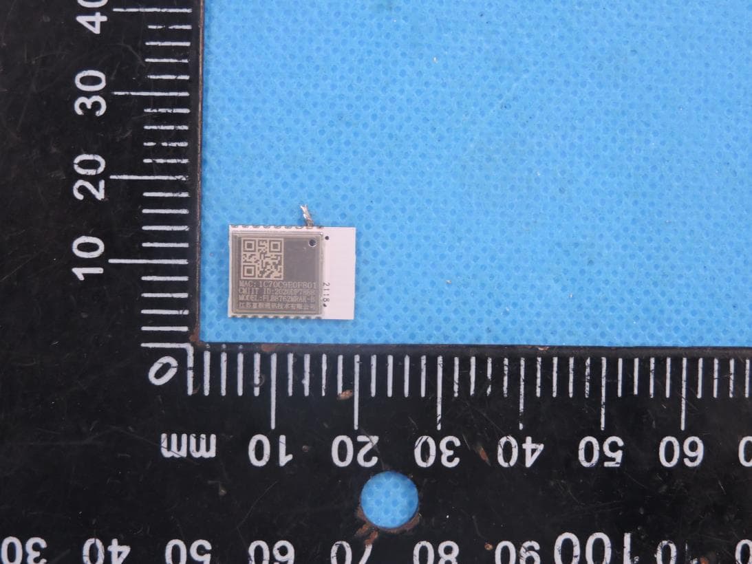
Click to zoom
Application Details
- Equipment Class
- DTS - Digital Transmission System
- Date of Grant
- Jul 30, 2023
- Application Purpose
- Original Equipment
- Date of Application
- Jul 30, 2023
- Equipment Note
- Bluetooth Module
- Frequency Range
- 2402.00000000 - 2480.00000000
- Country
- China
Documents & Files
Document Text
Text extracted from the exhibit documents filed with the FCC. Open a document above to read the original.
Users Manual
GY-BT7 BLE5.0 Bluetooth module Version 1.4 © Granwin IOT Technology (Guangzhou) Co.,Ltd GY-BT7 2/15 Module Introduction 1.1 Introduction The Guangyun IoT GY-BT7 Bluetooth module is the latest BLE 5.0 serial communication Bluetooth module launched by Guangyun IoT. It uses the Realtek RTL8762 chip and is equipped with Guangyun IoT mini programs, IoT apps, and IoT cloud platform development services, providing enterprises with fast, efficient and one-stop IoT solution services. This module is designed based on years of experience in IoT industry solutions from Guangyun IoT, and has the following advantages: Rapid development Guangyun IoT has designed and simplified the hexadecimal serial communication protocol for IoT product applications, reducing the development workload of MCU engineers and reducing the demand for MCU resources. Supporting WeChat mini programs, Android Apple APP, and cloud platform development services Guangyun IoT provides customized development, maintenance, and online services for IoT WeChat mini programs (domestic), IoT Android/Apple apps (domestic and foreign), and IoT cloud platforms (domestic and foreign) based on this Bluetooth module. 1.1 Module performance parameters Module performance parameters Section GY-BT7 Module Size 15*11.2*2.2mm Package Patch Antenna Onboard /IPEX Bluetooth version Bluetooth 5.0 Frequency band 2400 MHz~2483.5MHz GY-BT7 3/15 Transmitting power +8 dBm(MAX) Working mode UART Hardware interface PWM、UART、GPIO、ADC Supply Voltage 3.3V Supply Voltage Range 3.0V-3.6V Reserved peak current 50mA以上 Operating temperature range -40-85°C Storage Temperature Range -40-105°C Active TX mode 12mA Standby (deep sleep) 0.6uA(Implemented through firmware) GY-BT7 4/15 2 Module Hardware Description 2.1 Pin Definition 2.1.1 GY-BT7 Pin Definition Pin Definition Diagram Main Pin Definition Table Number Name Function Function Description 1,8 GND GND GND 2 VDD VDD_BAT 3.3V 5 RESET RESET Reset, low level active 9 P0_3 LOG_TX LOG output, pulled low when downloading firmware 13 P3_1 HCI UART RXD HCI UART RXD Download Firmware Usage 14 P3_0 HCI UART TXD HCI UART TXD Download Firmware Usage 16 P2_6 UART TXD UART TXD user serial port TX 17 P2_7 UART RXD UART RXD User Serial Port RX GY-BT7 5/15 1.1 Dimensional drawings 1.1.1 GY-BT7 Dimensional Drawing Dimension 3 Product Design Description 3.1 Reference schematic diagram GY-BT7 6/15 Schematic diagram of module peripheral design 3.2 IoT Product Design Reference (UED Guidance) IoT Product Design Reference Table Functional section UED requirements Trigger method for device pairing status 1. When the device is unbound and powered on, it enters the pairing state (implemented by the module and does not require MCU processing) 2. The user triggers the mold product to enter the pairing state through a button (achieved by sending instructions through the MCU) Device pairing status window time 30 minutes (implemented by the module, no MCU processing required) Trigger pairing Press and hold single or combination buttons for 7 seconds (implemented by MCU) Pairing status Indicator light flashing, on for 0.4s, off for 0.2s (achieved by MCU) (Please note that after receiving the module successfully entering the pairing command, perform the flash action. Do not press the key to trigger successfully and enter the flashing action. Otherwise, there may be a situation where the module has not entered the pairing state, but the product indicator light flashes, misleading the user. At the same time, there may be customer complaints due to the user's unsuccessful pairing.) Connected status Indicator light always on (implemented by MCU) Unconnected state Indicator light always off (implemented by MCU) GY-BT7 7/15 3.3 Antenna Design When the module is an onboard PCB antenna, it is required to have complete clearance directly below the antenna, and the area around the antenna should avoid metal to avoid affecting the antenna radiation efficiency and communication distance. Suggested placement area for module 3.4 Reflow soldering temperature curve Welding instructions: during double-sided SMT, after the first reflow of the top side components, the circuit board needs to be turned over for Reflow soldering on the other side. During the second reflow, the original soldered T side components will be fixed by the surface tension of the solder paste to prevent the components from falling under the action of gravity. The design of the motherboard has been verified to be free of defects through furnace temperature testing (240-250°C). To ensure its stability, it is recommended to apply glue. GY-BT7 8/15 Reflow soldering temperature curve GY-BT7 9/15 FCC Statement Any Changes or modifications not expressly approved by the party responsible for compliance could void the user's authority to operate the equipment. The modular can be installed or integrated in mobile or fix devices. This modular can be installed in any portable device. FCC Radiation Exposure Statement The device has been evaluated to meet general RF exposure requirement. The device can be used in portable exposure condition without restriction. If the FCC identification number is not visible when the module is installed inside another device, then the outside of the device into which the module is installed must also display a label referring to the enclosed module. This exterior label can use wording such as the following: “Contains Transmitter Module FCC ID: 2A58X -GY-BT7 Or Contains FCC ID: 2A58X -GY-BT7” When the module is installed inside another device, the user manual of the host must contain below warning statements; This device complies with Part 15 of the FCC Rules. Operation is subject to the following two conditions: (1) This device may not cause harmful interference. (2) This device must accept any interference received, including interference that may cause undesired operation. The devices must be installed and used in strict accordance with the manufacturer's instructions as des…
Text truncated - open the document above for the full version.
Attestation Statements
AOGES CO., LIMITED 1/1 US Agent for Service of Process LETTER OF ATTESTATION TO: Office of Engineering Technology Federal Communications Commission 7435 Oakland Mills Road Columbia, MD 21046 US Agent for Service of Process: Company Name: AOGES CO., LIMITED Contact Name: XIAOYAN LAI Address: Address: 1624 Market St., Ste 226, #30327 Denver CO, 80202 US Telephone No: +1 303 623 1940 Email: [email protected] FRN: 0033947847 Applicant: Company name: Granwin IOT Technology (Guangzhou) Co., Ltd Product Description: Bluetooth module Grantee code: 2A58X FCC ID: 2A58X-GY-BT7 Contact Name: Darren Zhuang Address: 801, block C, Runhui Science Park, Huangpu District, Guangzhou, China. Telephone No: 18576447653 Email: [email protected] [Granwin IOT Technology (Guangzhou) Co., Ltd] certifies that, as of the date of this filing of the application with the TCB, [AOGES CO., LIMITED] is our designated US agent for service of process for the above referenced FCC ID. [Granwin IOT Technology (Guangzhou) Co., Ltd] accepts to maintain an agent for no less than one year after the grantee has terminated all marketing and importation or the conclusion of any commission related proceeding involving equipment. [AOGES CO., LIMITED] accepts, as of the date of the filing of the application, the obligation of the designated US agent for service of process for the above reference FCC ID. The US Agent for Service of Process is aware of and agrees to comply with the requirements outlined in the FCC Equipment Authorization Program, Report and Order FCC 22-84, and clause § 2.911. The Applicant is aware of and agrees to comply with the requirements outlined in the FCC Equipment Authorization Program, Report and Order FCC 22-84, and clause § 2.911. Date: 2023/07/25 Applicant’s Name: Granwin IOT Technology (Guangzhou) Co., Ltd US Agent for Service of Process’s Name: AOGES CO., LIMITED Title:CSO Title: General Manager Signature Signature XIAOYAN LAI
Attestation Statements
C5266091_X24_Ed.2 1/1 “Attestation Statements” TO: Office of Engineering Technology Federal Communications Commission 7435 Oakland Mills Road Columbia, MD 21046 The Commission adopted rules that prohibit equipment authorization for “covered” telecommunications equipment and video surveillance equipment produced by entities identified on the Commission’s Covered List 1 , which is periodically updated. See the Covered List for more details. This Attestation Statement is to confirm that we follow the Section 2.911(d)(5)(i)-(ii) Applicant Company name: Granwin IOT Technology (Guangzhou) Co., Ltd Grantee code: 2A58X FCC ID: 2A58X-GY-BT7 Contact Name: Darren Zhuang Address: 801, block C, Runhui Science Park, Huangpu District, Guangzhou, China. Telephone No: 18576447653 Fax No: Email: [email protected] i. [Granwin IOT Technology (Guangzhou) Co., Ltd] (“the applicant”) certifies that the equipment for which authorization is sought is not “covered” equipment prohibited from receiving an equipment authorization pursuant to section 2.903 of the FCC rules. The applicant must sign this certification. ii. [Granwin IOT Technology (Guangzhou) Co., Ltd] (“the applicant”) certifies that, as of the date of the filing of the application, the applicant [is not] (as a specifically named entity or any of its subsidiaries or affiliates) identified on the Covered List as an entity producing “covered” equipment. The applicant must sign this certification. [Granwin IOT Technology (Guangzhou) Co., Ltd] (“the applicant”) certifies that, as of the date of the filing of the application, the applicant [is not] identified on the Covered List as an entity producing “covered” equipment. Date: 2023/07/25 Applicant’s Name: Granwin IOT Technology (Guangzhou) Co., Ltd Title:CSO Signature 1 The Commission’s Covered List is published by the Public Safety and Homeland Security Bureau and posted on the Commission’s website. This Covered List, which is periodically updated, identifies particular equipment, produced by particular entities, that constitutes “covered” equipment. https://www.fcc.gov/supplychain/coveredlist
Cover Letter(s)
C5266091_X8_Ed.1 1/1 Letter of Authorization Granwin IOT Technology (Guangzhou) Co., Ltd Company:Granwin IOT Technology (Guangzhou) Co., Ltd Address: 801, block C, Runhui Science Park, Huangpu District, Guangzhou, China. Product Name: Bluetooth module Model Number: GY-BT7 FCC Identifier: 2A58X-GY-BT7 We authorize LGAI Technological Center S.A., Ronda de la Font del Carme, s/n, 08193 Bellaterra, Spain, to act on our behalf on all matters concerning the above named equipment. Any individual within LGAI Technological Center S.A. is authorized to act on our behalf and take action on the application. We declare that authorize LGAI Technological Center S.A., Ronda de la Font del Carme, s/n, 08193 Bellaterra, Spain, is allowed to forward all information related to the approval project to the Federal Communication Commission and to discuss any issues concerning the approval application. Any and all acts carried out by LGAI Technological Center S.A. on our behalf shall have the same effect as acts of our own. Name: Darren Zhuang Date: 2023.07.25 Title: CSO Signature of applicant:
Cover Letter(s)
C5266091_X10_Ed.2 1/1 Granwin IOT Technology (Guangzhou) Co., Ltd Office of Engineering Technology Federal Communications Commission 7435 Oakland Mills Road Columbia, MD 21046 Date: 2023.07.25 Subject: Request for Confidentiality FCC ID: 2A58X-GY-BT7 To Whom It May Concern, Pursuant to the provisions of Sections 0.457 and 0.459 of Commission's rules (47CFR0.457, 0.459), we are requesting the Commission to withhold the following attachment(s) as confidential document from public disclosure. Exhibits Long-Term Confidentiality Short-Term Confidentiality NOTE 2 ID Label/Location No No Attestation Statement No No External Photos No ☐ Block Diagram ☒ ☐ Schematics ☒ ☐ Test Report No No Test Setup Photos No ☐ User’s Manual ☐ NOTE 1 ☐ Internal Photos ☐ NOTE 1 ☐ Parts List / Tune Up ☐ ☐ RF Exposure Info No No Operational Description ☒ ☐ Cover Letter(s) No No SDR Software / Security Info ☐ No NOTE 1: Long-Term Confidentiality may be permitted under special conditions (See II. LONG-TERM CONFIDENTIALITY, Section 3 of KDB 726920, use last in force) NOTE 2: Short-Term Confidentiality can be requested for a maximum of 180 days from the date of the grant. Above mentioned document contains detailed system and equipment description are considered as proprietary information in operation of the equipment. The public disclosure of above documents might be harmful to our company and would give competitor an unfair advantage in the market. In case of short-term Confidentiality, the applicant requests the exhibits selected above are withheld from public view for a period of ______ days from the date of the Grant of Equipment Authorization and prior to marketing. It is our understanding that all measurement test reports, FCC ID label format and correspondent during certification review process cannot be granted as confidential documents and those information will be available for public review once the grant of equipment authorization is issued. C5266091_X10_Ed.2 1/1 Sincerely, Signature: Name:Darren Zhuang Title:CSO
Cover Letter(s)
C5266091_X9_Ed.2 1/1 Granwin IOT Technology (Guangzhou) Co., Ltd Modular Transmitter Approval Request Federal Communications Commission Equipment Authorization Branch 7435 Oakland Mills Road Columbia, MD 21046 Company name: Granwin IOT Technology (Guangzhou) Co., Ltd FCC ID: 2A58X-GY-BT7 Gentlemen, In accordance with 47CFR 15.212 Modular Transmitters and KDB 996369 D01 ‘Module Certification Guide v01r04’. FCC ID 2A58X-GY-BT7 has been examined against the following requirements. Items to be covered by Single modular transmitters. Requirement per 15.212 and KDB 996369 D01 ‘Modular Certification Guide v02 Explanation from Grantee (do not write yes/no, but explain why product complies/how it is achieved) 1.The radio elements must have the radio frequency circuitry shielded. Physical components and tuning capacitor(s) may be located external to the shield, but must be on the module assembly Yes, with shielded 2.The module must have buffered modulation/data inputs to ensure that the device will comply with Part 15 requirements with any type of input signal Yes , All inputs to the modules are buffered through logic or microprocessor inputs. 3.The module must contain power supply regulation on the module Yes, A low drop out regulator (U 8 RTL8762) is used for modular power supply regulation. 4.The module must contain a permanently attached antenna, or contain a unique antenna connector, and be marketed and operated only with specific antenna(s), per Sections 15.203, 15.204(b), 15.204(c), 15.212(a), 2.929(b) Yes, Device is equipped with Integral antenna. 5.The module must demonstrate compliance in a stand- alone configuration Yes, The module test in a stand-alone configuration. 6.The module must be labelled with its permanently affixed FCC ID label, or use an electronic display (See KDB Publication 784748 about labelling requirements) Yes ,The modular has a permanent fixed label, and below statement was listed in the User Manual; The host device must be labeled to display the FCCID of the module Contains FCC ID: 2A58X-GY-BT7 7.The module must comply with all specific rules applicable to the transmitter including all the conditions provided in the integration instructions by the grantee Yes ,The module comply with all specific rules applicable to the transmitter including all the conditions provided in the integration instructions by the grantee, Refer to test report and user manual 8.The module must comply with RF exposure requirements Yes , Transmitter meets MPE calculation of 47 CFR 1.1307 . Refer to MPE Reports and Refer to modular installation manual C5266091_X9_Ed.2 1/1 A limited modular approval (LMA) may be granted for single or split modular transmitters that comply partially with requirements above. Name:Darren Zhuang Date: 2023.07.25 Title:CSO Signature of applicant
External Photos
Page 1 of 1 Report No.: STS2307027 APPENDIX-PHOTOGRAPHS OF EUT CONSTRUCTIONAL DETAILS Model: GY-BT7 Photo 1 Photo 2
ID Label/Location Info
FCC Label W:4mm L: 5mm Bluetooth Module Model name: GY-BT7 FCC ID: 2A58X -GY-BT7
Internal Photos
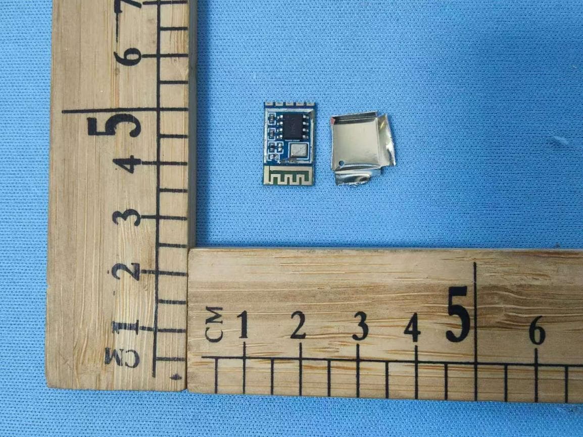
Page 1 of 1 Report No.: STS2307027 APPENDIX-PHOTOGRAPHS OF EUT CONSTRUCTIONAL DETAILS Model: GY-BT7 Photo 1 Photo 2 BLE Antenna
RF Exposure Info
Any reproduction of this document must be done in full. No single part of this document may be reproduced without permission from STS, all test data presented in this report is only applicable to presented test sample. Radio Test Report Report No: STS2307027H02 Issued for Granwin IOT Technology (Guangzhou) Co., Ltd 801, block C, Runhui Science Park, Huangpu District, Guangzhou, China. Product Name: Bluetooth module Brand Name: N/A Model Name: GY-BT7 FCC ID: 2A58X-GY-BT7 Test Standard: FCC 47CFR §2.1093 Page 2 of 10 Report No.: STS2307027H02 Test Report Certification Applicant’s Name ................. : Granwin IOT Technology (Guangzhou) Co., Ltd Address ................................. : 801, block C, Runhui Science Park, Huangpu District, Guangzhou, China. Manufacturer's Name .......... : Granwin IOT Technology (Guangzhou) Co., Ltd Address ................................. : 801, block C, Runhui Science Park, Huangpu District, Guangzhou, China. Product Description Product Name ........................ : Bluetooth module Brand ................................... : N/A Model Name .......................... : ... : GY-BT7 Standards ............................. : FCC 47CFR §2.1093 447498 D04 Interim General RF Exposure Guidance v01 This report shall not be reproduced except in full, without the written approval of STS, this document only be altered or revised by STS, personal only, and shall be noted in the revision of the document. Date of Test ............................................ : Date of receipt of test item ...................... : 05 July 2023 Date (s) of performance of tests ............. : 05 July 2023 ~ 18 July 2023 Date of Issue ........................................... : 18 July 2023 Test Result ............................................... : Pass Testing Engineer : (Aaron Bu) Technical Manager : (Sean she) Authorized Signatory : (Chris Chen) Page 3 of 10 Report No.: STS2307027H02 TABLE OF CONTENTS 1. GENERAL INFORMATION 5 1.1 GENERAL DESCRIPTION OF THE EUT 5 1.2 TEST FACTORY 6 2. FCC 47CFR §2.1093 REQUIREMENT 7 2.1 TEST STANDARDS 7 2.2 LIMIT 7 2.3 TEST RESULT 10 Page 4 of 10 Report No.: STS2307027H02 Revision History Rev. Issue Date Report No. Effect Page Contents 00 18 July 2023 STS2307027H02 ALL Initial Issue Page 5 of 10 Report No.: STS2307027H02 1. GENERAL INFORMATION 1.1 GENERAL DESCRIPTION OF THE EUT Product Name Bluetooth module Brand N/A Model Number GY-BT7 Series Model(s) N/A Model Difference N/A Product Description The EUT is Bluetooth module Operation Frequency: 2402~2480 MHz Modulation Type: GFSK Antenna gain: 0.61dBi Antenna Designation: PCB Rating Input:3.3V⎓500mA Hardware version number V1.0 Software version number V1.0 Page 6 of 10 Report No.: STS2307027H02 1.2 TEST FACTORY SHENZHEN STS TEST SERVICES CO., LTD Add. : 101, Building B, Zhuoke Science Park, No.190 Chongqing Road, ZhanChengShequ, Fuhai Sub-District, Bao’an District, Shenzhen, Guang Dong, China FCC test Firm Registration Number: 625569 IC test Firm Registration Number: 12108A A2LA Certificate No.: 4338.01 Page 7 of 10 Report No.: STS2307027H02 2. FCC 47CFR §2.1093 REQUIREMENT 2.1 TEST STANDARDS Follow the maximum permissible exposure (MPE) limits specified in 447498 D04 Interim General Radio Frequency Exposure Guidelines v01. The gain of the antenna used in the product was extracted from the supplied antenna data sheet and the maximum total power input to the antenna was also measured. Calculate the distance from the product to the MPE limit by the formula. 2.2 LIMIT For single RF sources (i.e., any single fixed RF source, mobile device, or portable device, as defined in paragraph (b)(2) of this section): A single RF source is exempt if: (A) The available maximum time-averaged power is no more than 1 mW, regardless of separation distance. This exemption may not be used in conjunction with other exemption criteria other than those in paragraph (b)(3)(ii)(A) of Part 1.1307. Medical implant devices may only use this exemption and that in paragraph (b)(3)(ii)(A); (B) Or the available maximum time-averaged power or effective radiated power (ERP), whichever is greater, is less than or equal to the threshold Pth (mW) described in the following formula. This method shall only be used at separation distances (cm) from 0.5 centimeters to 40 centimeters and at frequencies from 0.3 GHz to 6 GHz (inclusive). Pth is given by: Page 8 of 10 Report No.: STS2307027H02 (C) Or using below table and the minimum separation distance (R in meters) from the body of a nearby person for the frequency (f in MHz) at which the source operates, the ERP (watts) is no more than the calculated value prescribed for that frequency. For the exemption in Table 1 to apply, R must be at least λ/2π, where λ is the free-space operating wavelength in meters. If the ERP of a single RF source is not easily obtained, then the available maximum time-averaged power may be used in lieu of ERP if the physical dimensions of the radiating structure(s) do not exceed the electrical length of λ/4 or if the antenna gain is less than that of a half-wave dipole (1.64 linear value). RF Source frequency (MHz) Threshold ERP(watts) 0.3-1.34 1,920 R 2 . 1.34-30 3,450 R 2 /f 2 . 30-300 3.83 R 2 . 300-1,500 0.0128 R 2 f. 1,500-100,000 19.2R 2 . Page 9 of 10 Report No.: STS2307027H02 For multiple RF sources: Multiple RF sources are exempt if: (A) The available maximum time-averaged power of each source is no more than 1 mW and there is a separation distance of two centimeters between any portion of a radiating structure operating and the nearest portion of any other radiating structure in the same device, except if the sum of multiple sources is less than 1 mW during the time-averaging period, in which case they may be treated as a single source (separation is not required). This exemption may not be used in conjunction with other exemption criteria other than those is paragraph (b)(3)(i)(A) of Part 1.1307. Medical implant devices may only use this exem…
Text truncated - open the document above for the full version.
Test Report
Shenzhen Yingjia Chuang electronic technology Co.,LTD Product antenna commissioning report Date: June 30, 2023 Prepared by: Fang Huiming Reviewed by: Fang Wenfeng Approved by: Xiao Han Antenna Model:BT7 Shenzhen company address: Shenzhen Guangming District Ma Tian Office will Shi HongyuGuangming Valley A&C building Hangzhou company address: 212, Building B, Dahua Jianghong International Innovation Park, 369 Internet of Things Street, Binjiang District, Hangzhou Address: No. 4F-34 Wanxiang High-tech International, No. 35 Mianxing East Road, Mianyang High-tech Zone, Sichuan Province Add: Yingjiachuang Industrial Park, No. 2 Yinhe 3rd Road, Shishuikou, Qiaotou Town, Dongguan City Telephone:0755-27810060 fax:0755-27810057 website:http://www.szsyjc.com Email:[email protected] 一、Project Overview Customer name Project Name Antennaimple mentation 786 modules PCB antenna Operating frequency band(MHz) 2.4 2400-2500MHz Directory: 1、 cover。。。。。。。。。。。。。。。。。。。。。。。。。。1 2、 Project Overview。。。。。。。。。。。。。。。。。。。。。2 3、 directory。。。。。。。。。。。。。。。。。。。。。。。。3 4、 Antenna Location Map。。。。。。。。。。。。。。。。。。。4 5、 Antenna performance test diagram - Passive test data -2D 3D diagram。。。。。。。。。。。。。。。。。。。。。。。。。。。5-8 Antenna Location Map Antenna size Antenna performance test chart Antenna passive test data Frequency/MHz Efficiency/% Gain/dBi 2400 30.82 0.61 2410 29.95 0.42 2420 29.3 0.41 2430 27.73 0.37 2440 27.99 0.31 2450 26.58 0.26 2460 25.2 0.16 2470 23.92 -0.05 2480 22.55 -0.33 2490 22.5 -0.37 2500 20.77 -0.41 Antenna Antenna Test 2D/3D Diagram Phi 0 2D image Phi 90 2Dimage Theta 90 2Dimage 2400 2400 2500
Test Setup Photos
Page 1 of 2 FCC ID: 2A58X-GY-BT7 DTS Setup photo Model name: GY-BT7 DTS radiation L DTS radiation H Page 2 of 2 FCC ID: 2A58X-GY-BT7 DTS conduction 3
Contact Information
Applicant
Darren Zhuang
Technical Contact
Granwin IOT Technology (Guangzhou) Co., LtdDarren Zhuang
[email protected]18576447653
Guangzhou · China
Test Firm
SHENZHEN STS TEST SERVICES CO.,LTD.Bovey Yang
[email protected]+86 755-36886288
Technical Specifications
| # | Rule Parts | Frequency Range | Power Output |
|---|---|---|---|
| 1 | 15C | 2.40 GHz - 2.48 GHz | 2.00 mW |
Other Applications from Granwin IOT Technology (Guangzhou) Co., Ltd
2A58X-GY-BT2G
Jan 16, 2026GY-BT2G
Equipment Class
DTS - Digital Transmission System