2A5H7-PD800Dog training collar
Shenzhen PaiPai Technology Co., Ltd.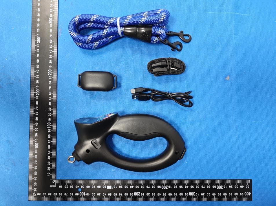
Click to zoom
Application Details
- Equipment Class
- DSC - Part 15 Security/Remote Control Transmitter
- Date of Grant
- Jan 16, 2024
- Application Purpose
- Original Equipment
- Date of Application
- Jan 16, 2024
- Equipment Note
- Dog training collar
- Frequency Range
- 434.33000000 - 434.33000000
- Country
- China
Documents & Files
Document Text
Text extracted from the exhibit documents filed with the FCC. Open a document above to read the original.
Users Manual
Ergonomic Control Handle Nylon Rope Style Leash Leash Identification Switch from Manual Mode to Auto Mode With Power On, press and release the power button once to switch from Manual to Auto. (Press again to switch back) Press"+"or"-" button to adjust vibration from Level 1 to Level 9 Press and release power button Double tap " " icon to check collar battery life: 5 Beeps = 100% 4 Beeps = 80% 3 Beeps = 60% 2 Beeps = 40% 1 Beep = 20% Red light will flash 10 seconds indicating battery life too low = shutting down NOTE: Leash must be in manual mode for testing. Button Identification Display Identification Power On Use short probes for short haired dogs Adjust the Vibration Level (Manual Mode Only) Press the vibration button Static Shock & Vibration Level Power/Program Vibration Beep Static Shock Static Shock & Vibration Level Adjustment Static Shock Icon Mode (Manual/Auto) Option Auto:0 Auto Mode Adjust the Static Shock Level (Manual Mode Only) Press the static shock or beep button TIPS:The static shock is very mild and it wouldn't hurt the dogs. It is designed to get their attention and should always be followed by a verbal command. Always begin training on Level 1 and work up to a proper level in accordance with your dog's size and temperament. The USB charging port for the smart leash handle can be found on the side as indicated in the photo. The USB charging port for the collar can be found on the bottom of the collar by lifting the rubber tab. We are now ready to attach the leash to the collar and leash-handle by using your thumb to open connector and place on collar and handle loop. You are ready to begin using Smart Leash. Please visit our Instructional guides for training tips. For best fit you should be able to slide one finger comfortably between, the collar and your dog’s neck. Leash ProbeRubber Probe Covers Static Shock Tester Control Handle Collar Charging Cord 1 2345678 Press and release " " button Beep Icon Vibration Icon Battery Life Manual:3 Auto:0 Manual:3 Auto:0Auto:0 Auto:0 Manual:1Manual:1 Manual:3Manual:3 Manual:3 Anti-Tugging Dog Training Collar System Device will automatically send a "Beep" signal when dog pulls 3 lbs. Device will automatically send a "Beep+Vibration" signal when dog pulls 5 lbs. Device will automatically send a "Beep+Vibration+Static Shock" signal when dog pulls 7 Ibs. When the device is in the Auto mode, the Manual mode still works. Short Rubber Probe Covers Press the "+" or "-" button to adjust the static shock from level 1 to level 9 To test for static shock, place the tester on the probes making sure the wires in the tester slots contact the probes. Then press the static shock button on the control handle and the tester will light up. Short Probes Long Rubber Probe Covers Long Probes Use long probes for long haired dogs The Anti-Tugging Dog Training Collar Package Includes Vibration levels Static Shock Levels Instructional Guide NOTE: We recommend attaching the leash to the dog's harness instead of the collar strap. Attaching the leash to the collar strap may cause discomfort or even injury to the dog. Please use it with caution. Avoid leaving the collar on the dog's neck for more than 18 hours per day. We recommend repositioning the collar on the dog's neck every 1 – 2 hours. NOTE: Collar should be adjusted to be snug but not tight around dog’s neck. FCC Caution: This device complies with part 15 of the FCC Rules. Operation is subject to the following two conditions: (1) This device may not cause harmful interference, and (2) this device must accept any interference received, including interference that may cause undesired operation. Any Changes or modifications not expressly approved by the party responsible for compliance could void the user's authority to operate the equipment. Note: This equipment has been tested and found to comply with the limits for a Class B digital device, pursuant to part 15 of the FCC Rules. These limits are designed to provide reasonable protection against harmful interference in a residential installation. This equipment generates uses and can radiate radio frequency energy and, if not installed and used in accordance with the instructions, may cause harmful interference to radio communications. However, there is no guarantee that interference will not occur in a particular installation. If this equipment does cause harmful interference to radio or television reception, which can be determined by turning the equipment off and on, the user is encouraged to try to correct the interference by one or more of the following measures: -Reorient or relocate the receiving antenna. -Increase the separation between the equipment and receiver. -Connect the equipment into an outlet on a circuit different from that to which the receiver is connected. -Consult the dealer or an experienced radio/TV technician for help. The device has been evaluated to meet general RF exposure requirement. The device can be used in portable exposure condition without restriction.
Attestation Statements
Shenzhen PaiPai TechnoIogy Co., Ltd. 2024.01.15 Eurofins Electrical and Electronic Testing NA, Inc. 914 West Patapsco Avenue Baltimore, MD 21230 RE: Attestation Statements Part 2.911(d)(5)(i) request for FCC ID: 2A5H7-PD800 [Shenzhen PaiPai TechnoIogy Co., Ltd.] (“the applicant”) certifies that the equipment for which authorization is sought is not “covered” equipment prohibited from receiving an equipment authorization pursuant to section 2.903 of the FCC rules. Sincerely, (Applicant signature) (Applicant printed name) JIANG YUANZHUO Shenzhen PaiPai TechnoIogy Co., Ltd. 2024.01.15 Eurofins Electrical and Electronic Testing NA, Inc. 914 West Patapsco Avenue Baltimore, MD 21230 RE: Attestation Statements Part 2.911(d)(5)(ii) request for FCC ID: 2A5H7-PD800 [Shenzhen PaiPai TechnoIogy Co., Ltd.] (“the applicant”) certifies that, as of the date of the filing of the application, the applicant is not identified on the Covered List as an entity producing “covered” equipment. Sincerely, (Applicant signature) (Applicant printed name) JIANG YUANZHUO
Cover Letter(s)
Shenzhen PaiPai TechnoIogy Co., Ltd. 2024.01.15 Eurofins Electrical and Electronic Testing NA, Inc. 914 W. Patapsco Avenue Baltimore, MD 21230 USA RE: CONFIDENTIALITY REQUEST FOR EUT NAME: Dog training collar Trademark: N/A MODEL : PD 800, PD 700, PD 810, PD 820, PD 830, PD 850, PD 860 FCC ID : 2A5H7-PD800 To Whom It May Concern: This letter serves as an official request for confidentiality under sections 0.457 and 0.459 of CFR 47. We have requested that the - Block Diagram - Schematics - Operational Description required to be submitted with this application be permanently withheld from public review. The above materials contain trade secrets and proprietary information not customarily released to the public. The public disclosure of these materials may be harmful to the applicant and provide unjustified benefits to its competitors. Please contact me if there is any information you may need. Sincerely, Client’s signature: Client’s name / title : JIANG YUANZHUO / Manager Contact information / address: Floor 3, Building A15, Taizhong Industrial Zone, No. 6, Ailian Xinjin Road, Longgang District, Shenzhen, Guangdong Province, China
Cover Letter(s)
Shenzhen PaiPai TechnoIogy Co., Ltd. 2024.01.15 Eurofins Electrical and Electronic Testing NA, Inc. 914 W. Patapsco Avenue Baltimore, MD 21230 USA RE: LETTER OF AGENT AUTHORIZATION To Whom It May Concern: We, the undersigned, hereby authorize Shenzhen BCTC Testing Co., Ltd to act on our behalf in all matters relating to application for equipment authorization, including the signing of all documents relating to these matters. We also hereby certify that no party to the application authorized hereunder is subject to the denial of benefits, including FCC benefits, pursuant to Section 5301 of the Anti-Drug Abuse Act of 1988, 21 U.S.C.853(a). This agreement expires one year from the current date. Sincerely, Client’s signature: Client’s name / title : JIANG YUANZHUO / Manager Contact information / address: Floor 3, Building A15, Taizhong Industrial Zone, No. 6, Ailian Xinjin Road, Longgang District, Shenzhen, Guangdong Province, China
Cover Letter(s)
Shenzhen PaiPai TechnoIogy Co., Ltd. Model Difference 2024-01-15 EUT NAME: Dog training collar MODEL : PD 800, PD 700, PD 810, PD 820, PD 830, PD 850, PD 860 FCC ID: 2A5H7-PD800 All the model are the same circuit and RF module, except model names and appearance of the color. Regards Sincerely Client’s signature: Client’s name / title : JIANG YUANZHUO / Manager Contact information / address: Floor 3, Building A15, Taizhong Industrial Zone, No. 6, Ailian Xinjin Road, Longgang District, Shenzhen, Guangdong Province, China
External Photos
External Photos
ID Label/Location Info
Size:30*15mm Dog training collar FCC ID: 2A5H7-PD800 s Label location
RF Exposure Info
RF EXPOSURE EVALUATION METHOD FCC ID: 2A5H7-PD800 Applicable standard: In accordance with FCC 47 CFR part 2 (2.1093) this device has been defined as a portable device which is defined as a transmitting device designed to be used so that the radiating structure(s) of the device is/are within 20 centimeters of the body of the user. Portable devices must be evaluated using the specified in FCC 47 CFR part 2 (2.1093) and ANSI/IEEEC95.1-1992. and had been tested in accordance with the measurement methods and procedures specified in IEEE 1528-2003. Per FCC KDB 447498 D01 v06, the 1-g and 10-g SAR test exclusion thresholds for 100 MHz to 6 GHz at test separation distances s 50 mm are determined by: SAR Test Exclusion Thresholds for 100 MHz – 6 GHz and ≤ 50 mm Approximate SAR Test Exclusion Power Thresholds at Selected Frequencies and Test Separation Distances are illustrated in the following Table. The 1-g and 10-g SAR test exclusion thresholds for 100 MHz to 6 GHz at test separation distances ≤ 50 mm are determined by: [(max. power of channel, including tune-up tolerance, mW)/(min. test separation distance, mm)] · [√f(GHz)] ≤ 3.0 for 1-g SAR and ≤ 7.5 for 10-g extremity SAR,where f(GHz) is the RF channel transmit frequency in GHz Power and distance are rounded to the nearest mW and mm before calculation The result is rounded to one decimal place for comparison The test exclusions are applicable only when the minimum test separation distance is ≤ 50 mm and for transmission frequencies between 100 MHz and 6 GHz. When the minimum test separation distance is < 5 mm, a distance of 5 mm is applied to determine SAR test exclusion. Modulation Test Channel Output Power (dBuV/m) Output Power (dBm) ASK 434.33 70.95 -28.95 Below 1GHz: dBm=dBuV/m-95.2-4.7 max possible output power (PK,ERP):-28±1dBm 3dBi logarithmic terms convert to numeric result is nearly 2 -27dBm=0.002mW [(max. power of channel, including tune-up tolerance, mW)/(min. test separation distance,mm)] · [√f(GHz)]=0.002/5*√0.43433=0.00026≤3.0 Conclusion: 1. [(max. power of channel, including tune-up tolerance, mW)/(min. test separation distance, mm)] * [√f(GHz)] < 3.0. 2. SAR Test Exclusion Thresholds is 3.0 for separation distance 5mm. Therefore, SAR test is not required.
Test Report
Material Specitication Manufacturer:Shenzhen Xinxiangda Precision Hardware Products Co., Ltd Address:Floor 1, Building B, Huapei Industrial Zone, No. 115, Baoye Road, Shangwei Community, Guanhu Street, Longhua District, Shenzhen 1. Type:Spring Antenna 2. Model no: PC001 3. Antenna gain value: 3dBi 4. Features: 1)Stable and reliable in performance 2)ROHS compliance 5. Antenna Dimensions(unit:mm) 6. Antenna material:Brass 7. Antenna wire diameter:0.8mm 8. Number of antenna coils:21 circles 9. Frequency:434.33Mhz 10. Antenna Picture: Spring wire diameter 0.8mm, outer diameter 5.4mm, number of turns 21
Test Report
No.:BCTC/RF-EMC-005 Page: 1 of 34 Edition:B.1 TEST REPORT Shenzhen BCTC Testing Co., Ltd. Report No.: BCTC2312565101E Applicant: Shenzhen PaiPai TechnoIogy Co., Ltd. Product Name: Dog training collar Test Model: PD 800 Tested Date: 2023-12-26 to 2024-01-04 Issued Date: 2024-01-04 Report No.: BCTC2312565101E No.:BCTC/RF-EMC-005 Page: 2 of 34 Edition:B.1 FCC ID: 2A5H7-PD800 The test report is effective only with both signature and specialized stamp. This result(s) shown in this report refer only to the sample(s) tested. Without written approval of Shenzhen BCTC Testing Co., Ltd, this report can’t be reproduced except in full. The tested sample(s) and the sample information are provided by the client. Product Name: Dog training collar Trademark: N/A Model/Type reference: PD 800 PD 700, PD 810, PD 820, PD 830, PD 850, PD 860 Prepared For: Shenzhen PaiPai TechnoIogy Co., Ltd. Address: Floor 3, Building A15, Taizhong Industrial Zone, No. 6, Ailian Xinjin Road, Longgang District, Shenzhen, Guangdong Province, China Manufacturer: Shenzhen PaiPai TechnoIogy Co., Ltd. Address: Floor 3, Building A15, Taizhong Industrial Zone, No. 6, Ailian Xinjin Road, Longgang District, Shenzhen, Guangdong Province, China Prepared By: Shenzhen BCTC Testing Co., Ltd. Address: 1-2/F., Building B, Pengzhou Industrial Park, No.158, Fuyuan 1st Road, Zhancheng, Fuhai Subdistrict, Bao'an District, Shenzhen, Guangdong, China Sample Received Date: 202312-26 Sample tested Date: 2023-12-26 to 2024-01-04 Issue Date: 2024-01-04 Report No.: BCTC2312565101E Test Standards: FCC Part15.231 ANSI C63.10-2013 Test Results: PASS Tested by: Approved by: Lei Chen/Project Handler Zero Zhou/Reviewer Report No.: BCTC2312565101E No.:BCTC/RF-EMC-005 Page: 3 of 34 Edition:B.1 Table Of Content Test Report Declaration Page 1. Version .................................................................................................................. 4 2. Test Summary ....................................................................................................... 5 3. Measurement Uncertainty ..................................................................................... 6 4. Product Information And Test Setup ..................................................................... 7 4.1 Product Information ............................................................................................... 7 4.2 Test Setup Configuration ...................................................................................... 7 4.3 Support Equipment ............................................................................................... 8 4.4 Channel List .......................................................................................................... 8 4.5 Test Mode ............................................................................................................. 8 5. Test Facility And Test Instrument Used ................................................................. 9 5.1 Test Facility ........................................................................................................... 9 5.2 Test Instrument Used ............................................................................................ 9 6. Conducted Emissions .......................................................................................... 11 6.1 Block Diagram Of Test Setup .............................................................................. 11 6.2 Limit .................................................................................................................... 11 6.3 Test Procedure ................................................................................................... 11 6.4 EUT Operating Conditions .................................................................................. 12 6.5 Test Result .......................................................................................................... 13 7. Radiated Emissions ............................................................................................. 15 7.1 Block Diagram Of Test Setup .............................................................................. 15 7.2 Limit .................................................................................................................... 16 7.3 Test Procedure ................................................................................................... 17 7.4 EUT Operating Conditions .................................................................................. 19 7.5 Test Result .......................................................................................................... 19 8. Bandwidth Test .................................................................................................... 23 8.1 Block Diagram Of Test Setup .............................................................................. 23 8.2 Limit .................................................................................................................... 23 8.3 Test Procedure ................................................................................................... 23 8.4 EUT Operating Conditions .................................................................................. 23 8.5 Test Result .......................................................................................................... 24 9. Calculation Of Average Factor ............................................................................ 25 10. Dwell Time........................................................................................................... 28 10.1 Block Diagram Of Test Setup ............................................................................ 28 10.2 Limit .................................................................................................................. 28 10.3 Test Procedure ...............................................................................…
Text truncated - open the document above for the full version.
Test Setup Photos
Report No.: BCTC2312565101E No.:BCTC/RF-EMC-005 Page: 32 of 34 Edition: B.1 13. EUT Test Setup Photographs Conducted Emissions Photo Radiated Measurement Photos Report No.: BCTC2312565101E No.:BCTC/RF-EMC-005 Page: 33 of 34 Edition: B.1
Contact Information
Applicant
JIANG YUANZHUO(Manager)
Test Firm
Shenzhen BCTC Testing Co., Ltd.Sally He
[email protected]15999690624
Technical Specifications
| # | Rule Parts | Frequency Range | Power Output |
|---|---|---|---|
| 1 | 15.231 | 434.33 MHz - 434.33 MHz | - |