2A5TA-X7Bone conductive headphone
Shenzhen Zhengyun Technology Co., LTD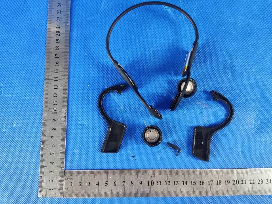
Click to zoom
Application Details
- Equipment Class
- DSS - Part 15 Spread Spectrum Transmitter
- Date of Grant
- Aug 03, 2022
- Application Purpose
- Original Equipment
- Date of Application
- Aug 03, 2022
- Equipment Note
- Bone conductive headphone
- Frequency Range
- 2402.00000000 - 2480.00000000
- Country
- China
Documents & Files
Document Text
Text extracted from the exhibit documents filed with the FCC. Open a document above to read the original.
Users Manual
X7 Bone Conduc�ve Headphone User Manual Direc�ons To Use X7 Headphone Power On To press the power bu�on for 2 seconds �ll the LED indicator blinks RED and BLUE alternately, the headphone is turned on and ready for Bluetooth connec�on. Bluetooth Connec�on At the first �me to use, a�er the headphone is turned on, it will be searched in the Bluetooth se�ngs mode of your devices (mobile phone or music player). Then you will find “X7” and select it in your Bluetooth devices found. When X7 is connected success, the blue indicator will blink slowly and when music playing, the indicator will be turned off. ①Power ON/OFF &Volume Down ②Volume up ③ Microphone ④Indicator ⑤USB Charging port Accessories List 1.X7 bone conduc�ve headphone 2.USB charging cable 3.Instruc�on manual Power Off To press the power bu�on for 3 seconds to turn off the headphone.It also can be shut down automa�cally if there is no pairing or connec�on for 180 seconds. Low Power Alarm & Charging Normally the mobile phone will display the headphone power status. If the ba�ery voltage is lower than 3.4V, you will hear the low power alarm for every 120 seconds. Once the ba�ery voltage dropped to 3.2V, headphone will be turned off automa�cally. Then please use the USB cable to plug into power adaptor for charging. Opera�on Instruc�on: POWER ON/OFF, VOLUME DOWN 1.Push the bu�on for 2 seconds to turn on 2.Push the bu�on for 3 seconds to turn off 3.Double clicks for next song 4.Triple clicks for Volume Down VOLUME UP To play music: 1.Click for Play/Pause 2.Double clicks for previous song 3.Triple clicks for volume up (Beep sound when reach the max. volume) 4.Push the bu�on for 2 seconds to call AI assistant (like “siri”) To answer the call 5.Click for calling answer 6.Push bu�on for 2 seconds to dismiss the call 7.Click for conversa�on ended 8.Double clicks to end the call and answer third party call Product Specifica�on *Model name: X7 *Bluetooth version: 5.0 *Net weight: 31.5g *Ba�ery capacity: 320mAH *Power input: 5V1A *Ba�ery charging �me: 2 hours *Music playback: 12 hours at 70% volume *Waterproof: IP55 *Transmission distance: 10 meters *Protocol support: A2DP,AVRCP,HSP,HFP Trouble Shoo�ng 1.Unable to turn on headphone =>Please make sure the ba�ery was fully charged and power bu�on was pressed on right posi�on. 2.Unable to connect headphone =>Please make sure the indicator LED is on the status of RED and BLUE blinking alternately. If the indicator blink BLUE slowly, the headphone was connected by other device. Please disconnect the device and try again. 3.Unable to reconnect headphone =>please make sure Bluetooth on your device was turned on. 4.Less transmission distance =>Please make sure your Bluetooth version of device is 4.0 above. The old version Bluetooth may cause shorter transmission distance. Indicators Descrip�on 1.Alternate RED and BLUE : wai�ng for pairing 2.BLUE for 3 seconds then turned off: Bluetooth connected 3.RED: under power charging 4.BLUE: ba�ery is fully charged Product Graphic and Accessories Quality Inspector Paired Device Replacement Disconnect the Bluetooth of your current paired device, then the headphone indicator will blink RED and BLUE alternately again. Other devices can find “X7” and available for connec�on. 70 在 IP55 This equipment has been tested and found to comply with the limits for a Class B digital device, pursuant to part 15 of the FCC Rules. These limits are designed to provide reasonable protection against harmful interference in a residential installation. This equipment generates, uses and can radiate radio frequency energy and, if not installed and used in accordance with the instructions, may cause harmful interference to radio communications. However, there is no guarantee that interference will not occur in a particular installation. If this equipment does cause harmful interference to radio or television reception, which can be determined by turning the equipment off and on, the user is encouraged to try to correct the interference by one or more of the following measures: •Reorient or relocate the receiving antenna. •Increase the separation between the equipment and receiver. •Connect the equipment into an outlet on a circuit different from that to which the receiver is connected. •Consult the dealer or an experienced radio/TV technician for help. Caution: Any changes or modifications to this device not explicitly approved by manufacturer could void your authority to operate this equipment. This device complies with part 15 of the FCC Rules. Operation is subject to the following two conditions: (1) This device may not cause harmful interference, and (2) this device must accept any interference received, including interference that may cause undesired operation. RF Exposure Information The device has been evaluated to meet general RF exposure requirement. The device can be used in portable exposure condition without restriction. FCC Statement
ID Label/Location Info
FCC ID Label FCC ID: 2A5TA-X7
Internal Photos
Page 1 of 4 FCC ID: 2A5TA-X7 Dongguan Yaxu (AiT) Technology Limited No.22, Jinqianling 3rd Street, Jitigang, Huangjiang, Dongguan, Guangdong, China. Internal Photos Photo 1 Photo 2 Page 2 of 4 FCC ID: 2A5TA-X7 Dongguan Yaxu (AiT) Technology Limited No.22, Jinqianling 3rd Street, Jitigang, Huangjiang, Dongguan, Guangdong, China. Photo 3 Photo 4 Page 3 of 4 FCC ID: 2A5TA-X7 Dongguan Yaxu (AiT) Technology Limited No.22, Jinqianling 3rd Street, Jitigang, Huangjiang, Dongguan, Guangdong, China. Photo 5 Photo 6 Antenna Page 4 of 4 FCC ID: 2A5TA-X7 Dongguan Yaxu (AiT) Technology Limited No.22, Jinqianling 3rd Street, Jitigang, Huangjiang, Dongguan, Guangdong, China. Photo 7 ------End------
RF Exposure Info
RF Exposure evaluation FCC ID: 2A5TA-X7 1.1. Applicable Standard According to §1.1307(b)(1), systems operating under the provisions of this section shall be operated in a manner that ensures that the public is not exposed to radio frequency energy level in excess of the Commission’s guidelines. According to §1.1310 and §2.1093 RF exposure requirement KDB447498 v06: Mobile and Portable Devices RF Exposure Procedures and Equipment Authorization Policies 1.2. Requirement According to KDB447498 D01 General RF Exposure Guidance v06 Section 4.3.1 Standalone SAR test exclusion considerations: “Unless specifically required by the published RF exposure KDB procedures, standalone 1-g head or body and 10-g extremity SAR evaluation for general population exposure conditions, by measurement or numerical simulation, is not required when the corresponding SAR Test Exclusion Threshold condition, listed below, is satisfied. These test exclusion conditions are based on source-based time-averaged maximum conducted output power of the RF channel requiring evaluation, adjusted for tune-up tolerance, and the minimum test separation distance required for the exposure conditions.22 The minimum test separation distance is determined by the smallest distance from the antenna and radiating structures or outer surface of the device, according to the host form factor, exposure conditions and platform requirements, to any part of the body or extremity of a user or bystander (see 5) of section 4.1). To qualify for SAR test exclusion, the test separation distances applied must be fully explained and justified by the operating configurations and exposure conditions of the transmitter and applicable host platform requirements, typically in the SAR measurement or SAR analysis report, according to the required published RF exposure KDB procedures. When no other RF exposure testing or reporting is required, a statement of justification and compliance must be included in the equipment approval, in lieu of the SAR report, to qualify for the SAR test exclusion. When required, the device specific conditions described in the other published RF exposure KDB procedures must be satisfied before applying these SAR test exclusion provisions; for example, handheld PTT two-way radios, handsets, laptops & tablets etc.23 “ [(max. power of channel, including tune-up tolerance, mW)/ (min. test separation distance, mm)] · [√f (GHz)] ≤ 3.0 for 1-g SAR and ≤ 7.5 for 10-g extremity SAR, where: • f (GHz) is the RF channel transmit frequency in GHz • Power and distance are rounded to the nearest mW and mm before calculation • The result is rounded to one decimal place for comparison • 3.0 and 7.5 are referred to as the numeric thresholds in the step 2 below The test exclusions are applicable only when the minimum test separation distance is ≤ 50 mm and for transmission frequencies between 100 MHz and 6 GHz. When the minimum test separation distance is < 5 mm, a distance of 5 mm according to 5) in section 4.1 is applied to determine SAR test exclusion. [Bluetooth] GFSK (Peak) Channel Channel 0 Channel 39 Channel 78 Target (dBm) 1 -1 -2 Tolerance ±(dB) 1.0 1.0 1.0 π/4DQPSK (Peak) Channel Channel 0 Channel 39 Channel 78 Target (dBm) 3 1 -1 Tolerance ±(dB) 1.0 1.0 1.0 8DPSK (Peak) Channel Channel 0 Channel 39 Channel 78 Target (dBm) 2 1 0 Tolerance ±(dB) 1.0 1.0 1.0 2. Evaluation Result Standalone Antenna 1 Band/Mode f (GHz) Antenna Distance (mm) RF output power including tune up SAR Test Exclusion Threshold SAR Test Exclusion Estimated SAR dBm mW BT 2.55 42.510.794< 3 Yes 0.1059 Remark: 1. Output power including tune up tolerance; 2. When the minimum test separation distance is < 5 mm, a distance of 5 mm according to f) in section 4.1 is applied to determine SAR test exclusion. 3. Conclusion The measurement results comply with the FCC Limit per 47 CFR 2.1093 for the uncontrolled RF Exposure and SAR Exclusion Threshold per KDB 447498 v06, No SAR is required. .....................End.........................
Test Report
Page 1 of 38 Report No.: AIT22072502W1 Dongguan Yaxu (AiT) Technology Limited No.22, Jinqianling 3rd Street, Jitigang, Huangjiang, Dongguan, Guangdong, China. TEST REPORT Client Information: Applicant: Shenzhen Zhengyun Technology Co., LTD Applicant add.: Room 202, Floor 2, Building A, Rongcheng International, 24 Heping Road, Qinghua Community, Longhua District, Shenzhen Manufacturer: Shenzhen Zhengyun Technology Co., LTD Manufacturer add.: Room 202, Floor 2, Building A, Rongcheng International, 24 Heping Road, Qinghua Community, Longhua District, Shenzhen Product Information: Product Name: Bone conductive headphone Model No.: X7, X8,X9,X10,X11,X13,X15,X16,X17,X18,X19 Brand Name: JINGYUN FCC ID: 2A5TA-X7 Applicable standards : FCC CFR Title 47 Part 15 Subpart C Section 15.247 Prepared By: Dongguan Yaxu (AiT) Technology Limited No.22, Jinqianling 3rd Street, Jitigang, Huangjiang,Dongguan, Guangdong, China Tel.: +86-769-8202 0499 Fax.: +86-769-8202 0495 Date of Receipt: July 25,2022 Date of Test: July 25,2022~July 28,2022 Date of Issue: July 29,2022 Test Result: Pass This device described above has been tested by Dongguan Yaxu (AiT) Technology Limited and the test results show that the equipment under test (EUT) is in compliance with the FCC requirements. And it is applicable only to the tested sample identified in the report. Note: This report shall not be reproduced except in full, without the written approval of Dongguan Yaxu (AiT) Technology Limited, this document may be altered or revised by Dongguan Yaxu (AiT) Technology Limited, personal only, and shall be noted in the revision of the document. This test report must not be used by the client to claim product endorsement. Reviewed by: Approved by: Simba Huang Seal.chen Page 2 of 38 Report No.: AIT22072502W1 Dongguan Yaxu (AiT) Technology Limited No.22, Jinqianling 3rd Street, Jitigang, Huangjiang, Dongguan, Guangdong, China. 1 Contents Page COVER PAGE 1 CONTENTS .................................................................................................................................................................... 2 2 TEST SUMMARY .......................................................................................................................................................... 4 2.1 Statement of the Measurement Uncertainty .............................................................................. 4 2.2 Measurement Uncertainty ......................................................................................................... 4 3 TEST FACILITY ............................................................................................................................................................. 5 3.1 Deviation from standard ............................................................................................................ 5 3.2 Abnormalities from standard conditions .................................................................................... 5 3.3 Test Location ............................................................................................................................. 5 4 GENERAL INFORMATION ......................................................................................................................................... 6 4.1 Test frequencies ........................................................................................................................ 7 4.2 EUT Peripheral List ................................................................................................................... 8 4.3 Test Peripheral List ................................................................................................................... 8 4.4 TEST METHODOLOGY............................................................................................................ 9 4.5 Description of Test Modes ....................................................................................................... 10 5 EQUIPMENT USED DURING TEST ........................................................................................................................ 11 6 TEST RESULTS AND MEASUREMENT DATA .................................................................................................... 12 6.1 Antenna requirement .............................................................................................................. 12 6.2 Peak Power Measurement ...................................................................................................... 13 6.3 Frequency Separation and 20 dB Bandwidth .......................................................................... 15 6.4 Number of Hopping Frequency ............................................................................................... 17 6.5 Time of Occupancy (Dwell Time) ............................................................................................ 18 6.6 Conducted Spurious Emissions and Band Edges Test ........................................................... 20 6.7 Restrict-band Band-edge Measurements ............................................................................... 22 6.8 Radiated Emissions Measurement ......................................................................................... 24 6.9 Conducted Emissions ............................................................................................................. 34 6.10 Pseudorandom frequency hopping sequence ......................................................................... 37 7 TEST SETUP PHOTOGRAPHS OF EUT ................................................................................................................ 38 8 EXTERNAL PHOTOGRAPHS OF EUT ................................................................................................................... 38 9 INTERNAL PHOTOGRAPHS OF EUT ................................................................................................…
Text truncated - open the document above for the full version.
Test Report
Dongguan Yaxu(AiT) Technology Limited Report No.: AIT22072502W1 FCC ID: 2A5TA-X7 Page 1 of 61 Appendix A RF Test Data for BT(BDR/EDR) (Conducted Measurement) Product Name: Bone conductive headphone Trade Mark: JINGYUN Test Model: X7 Environmental Conditions Temperature: 25.2°C Relative Humidity: 51.2% ATM Pressure: 101Kpa Test Engineer: Simba Huang Supervised by: Seal Chen Dongguan Yaxu(AiT) Technology Limited Report No.: AIT22072502W1 FCC ID: 2A5TA-X7 Page 2 of 61 Contents Page COVER PAGE 1 Duty Cycle ........................................................................................................................................................................................... 3 1.1 Test Result ............................................................................................................................................................................... 3 1.2 Test Graphs ............................................................................................................................................................................. 4 2 Maximum Conducted Peak Output Power .......................................................................................................................................... 9 2.1 Test Result ............................................................................................................................................................................... 9 2.2 Test Graphs ........................................................................................................................................................................... 10 3 20dB Bandwidth ................................................................................................................................................................................ 15 3.1 Test Result ............................................................................................................................................................................. 15 3.2 Test Graphs ........................................................................................................................................................................... 16 4 Carrier Frequency Separation ........................................................................................................................................................... 21 4.1 Test Result ............................................................................................................................................................................. 21 4.2 Test Graphs ........................................................................................................................................................................... 22 5 Hopping Channel Number ................................................................................................................................................................. 24 5.1 Test Result ............................................................................................................................................................................. 24 5.2 Test Graphs ........................................................................................................................................................................... 25 6 Dwell Time ......................................................................................................................................................................................... 27 6.1 Test Result ............................................................................................................................................................................. 27 6.2 Test Graphs ........................................................................................................................................................................... 28 7 RF Conducted Spurious Emissions ................................................................................................................................................... 31 7.1 Test Result ............................................................................................................................................................................. 31 7.2 Test Graphs ........................................................................................................................................................................... 32 8 Band-edge for RF Conducted Emissions .......................................................................................................................................... 41 8.1 Test Result ............................................................................................................................................................................. 41 8.2 Test Graphs ........................................................................................................................................................................... 42 9 Restrict-band band-edge measurements .......................................................................................................................................... 54 9.1 Test Result ............................................................................................................................................................................. 54 9.2 Test Graphs ........................................................................................................................................................................... 56 Dongguan Yaxu(AiT) Technology Limited Report No.: AIT22072502W1 FCC ID: 2A5TA-X7 Page 3 of 61 1 Duty Cycle 1.1 Test Result Mode Frequency (MHz) Duty Cycle (%) 1/T (kHz) 1-DH1 2402 32.8 2.5 1-DH1 2441 32.44 2.5 1-DH1 2480 32.8 2.5 2-DH1 2402 33.6 2.44 2-DH1 2441 32.8 2.5 2-DH1 2480 33.61 2.44 3-DH1 2402 33.6 2.44 3-DH1 2441 33.41 2.5 3-D…
Text truncated - open the document above for the full version.
Test Setup Photos
Page 1 of 2 FCC ID: 2A5TA-X7 Dongguan Yaxu (AiT) Technology Limited No.22, Jinqianling 3rd Street, Jitigang, Huangjiang, Dongguan, Guangdong, China. Test Setup Photo Radiated Emission Page 2 of 2 FCC ID: 2A5TA-X7 Dongguan Yaxu (AiT) Technology Limited No.22, Jinqianling 3rd Street, Jitigang, Huangjiang, Dongguan, Guangdong, China. Conducted Emission ------End------
Contact Information
Applicant
Wei Zeng
Test Firm
Dongguan Yaxu (AiT) Technology LimitedCoin Tang
[email protected]+86 0769-82020499-21
Technical Specifications
| # | Rule Parts | Frequency Range | Power Output |
|---|---|---|---|
| 1 | 15C | 2.40 GHz - 2.48 GHz | 1.90 mW |
Other Applications from Shenzhen Zhengyun Technology Co., LTD
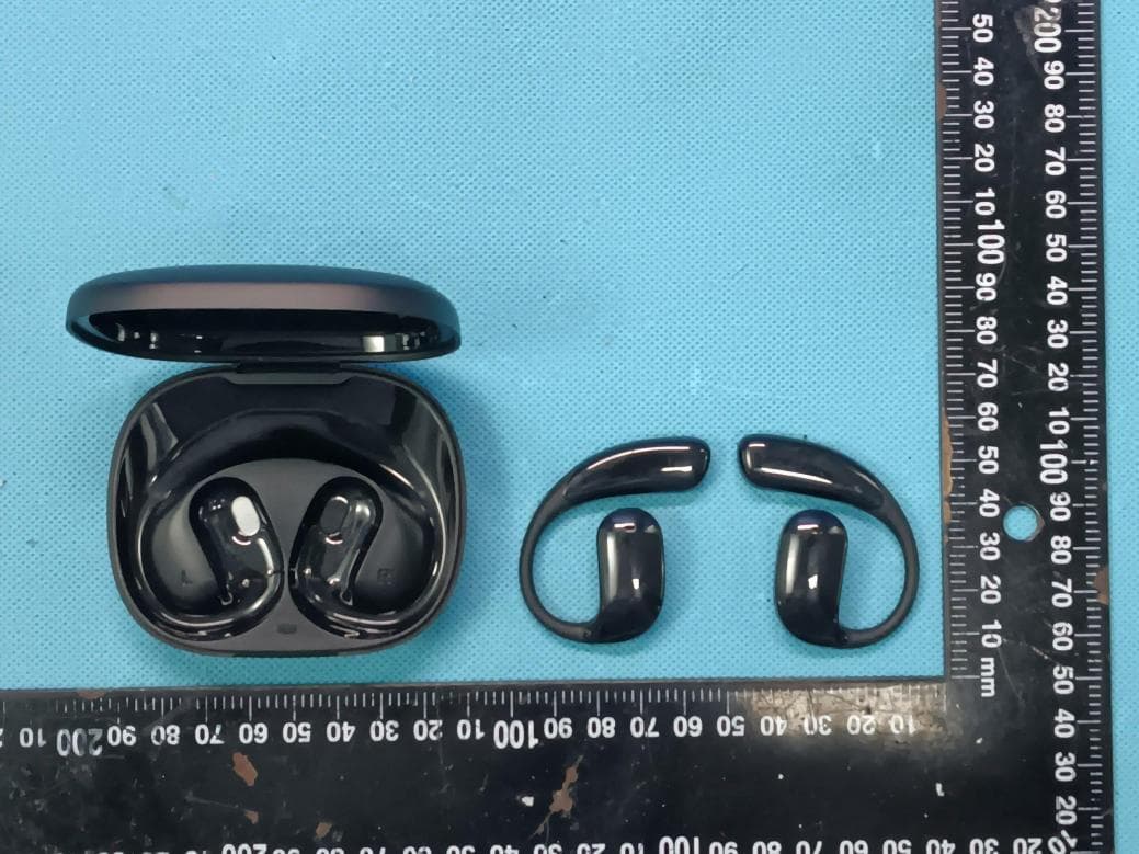
2A5TA-JER1
Jul 06, 2026Wireless Earbuds
Equipment Class
DTS - Digital Transmission System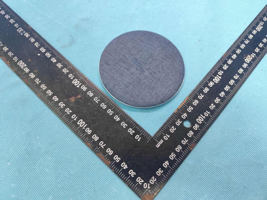
2A5TA-X50
Jun 16, 2026Speaker
Equipment Class
DSS - Part 15 Spread Spectrum Transmitter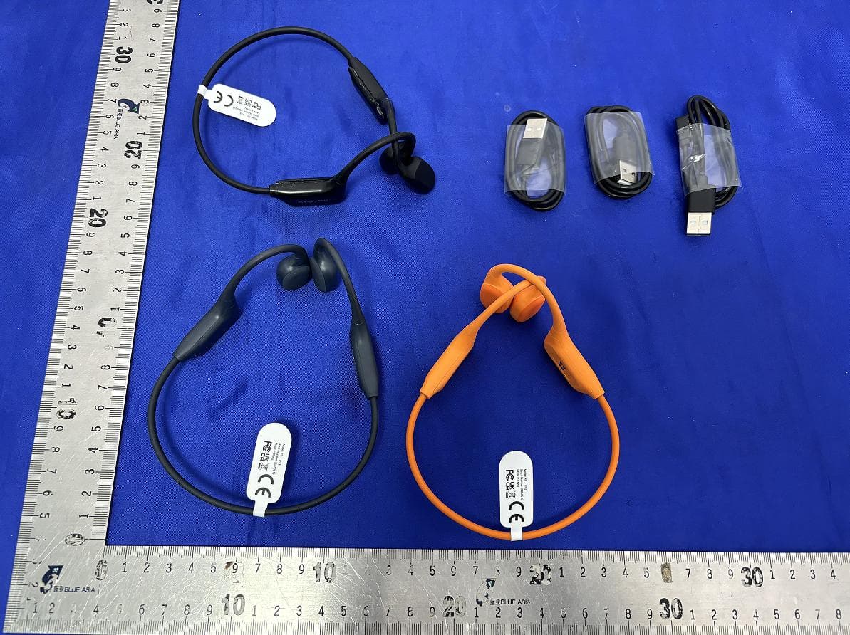
2A5TA-X9
Jun 16, 2026Wireless Earphones
Equipment Class
DSS - Part 15 Spread Spectrum Transmitter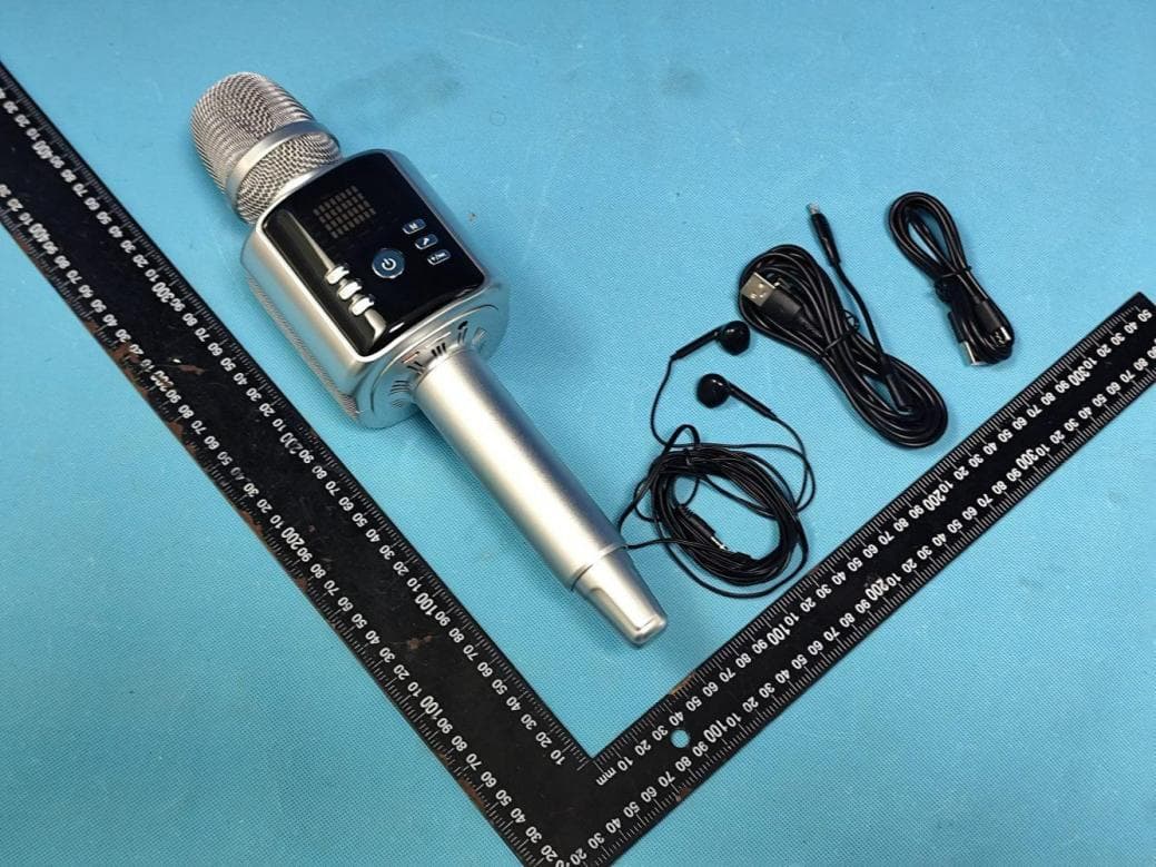
2A5TA-H9
Mar 24, 2026H9 karaoke live streaming microphone
Equipment Class
DSS - Part 15 Spread Spectrum Transmitter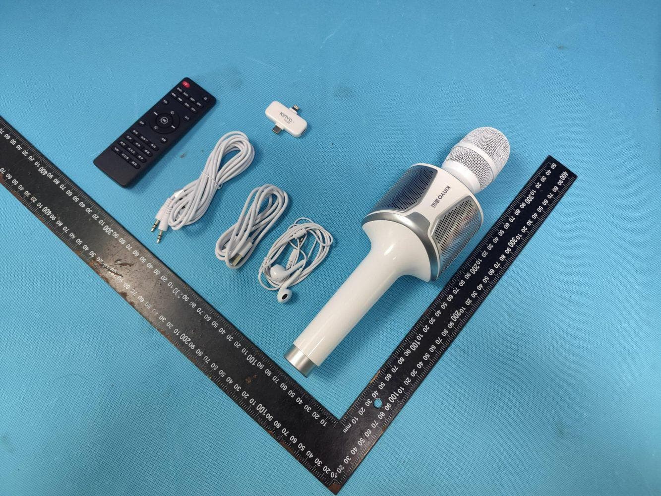
2A5TA-H100
Mar 24, 2026H100 karaoke live streaming microphone
Equipment Class
DSS - Part 15 Spread Spectrum Transmitter