2A5WF-ZE-CPE820wireless bridge
Shenzhen Zhier Network Technology Co., Ltd.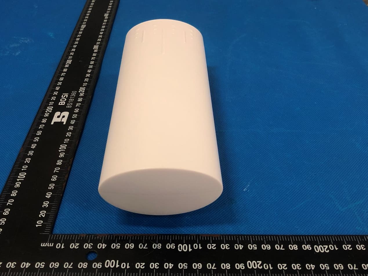
Click to zoom
Application Details
- Equipment Class
- NII - Unlicensed National Information Infrastructure TX
- Date of Grant
- Nov 20, 2022
- Application Purpose
- Original Equipment
- Date of Application
- Nov 20, 2022
- Equipment Note
- wireless bridge
- Frequency Range
- 5745.00000000 - 5825.00000000
- Country
- China
Documents & Files
Document Text
Text extracted from the exhibit documents filed with the FCC. Open a document above to read the original.
Users Manual
LEDA IP B IP 0 7 6 5 4 3 2 1 192.168.255.100 E D C b a 9 8 192.168.255.200 192.168.255.101 192.168.255.201 2.4 ID 5.8 ID 0 0 1 165 192.168.255.102 192.168.255.202 192.168.255.107 192.168.255.106 192.168.255.106 192.168.255.104 192.168.255.103 192.168.255.111 192.168.255.110 192.168.255.109 192.168.255.108 192.168.255.112 192.168.255.113 192.168.255.114 192.168.255.214 192.168.255.213 192.168.255.212 192.168.255.211 192.168.255.210 192.168.255.209 192.168.255.208 192.168.255.207 192.168.255.206 192.168.255.205 192.168.255.204 192.168.255.203 108 116 124 132 140 36 40 44 48 149 153 157 161 2 3 4 5 6 50 96 13 11 10 9 8 7 F 192.168.255.115 192.168.255.215 55 100 Digital Display Wireless Bridge 1. First Set A B A-B mode DIP switch, led L appears and blinks. After the disappearance of L shows an arrangement remain successful. 2. The reset button to set the led digital display, click the startup configuration status, then click the automatic increase. Can be continuously increased 3. Assume that a pair of bridges with a number of 1 is configured After A set to 1, after the B set to 1, during the LED will flash, L application configuration appears blinking, wait, L foot after flashing into a digital 1, 1 will continue to flash until the A, B are connected After the success, the LED display 1 is always on, not flashing, indicating that the AB has been successfully networked. +/-(1-5s) RST(10s) LAN2(PoE) LAN1(POE) A B DC(9-12V) PoE LAN PoE Adapter Digital Bridge-A Master Mode (IPC receiver) +/-(1-5s) RST(10s) LAN2(PoE) LAN1(POE) A B DC(9-12V) PoE LAN PoE Adapter Digital Bridge-B Slave Mode (IPC transmitter) Switch Computer Camera Usually near NVR Switch Computer Camera At the IPC end LAN1 LAN2 LED Link LED PWR LED RST RST Round light Bridge connection is successful, link lights, not connected Off Press over 10s, release the reset, the system automatically restart 1-5s press, led digital automatic increase, 0-F from circulation A, B status lights, light that is not mode A, mode B light that Flashing, it indicates to modify the configuration, or is connected to the L displayed and flashes, represents settings Display H, expressed configured to manually set state Power indicator, power on Turning on the lighting data, the communication flashing, off data nowhere LEDA IP B IP 0 7 6 5 4 3 2 1 192.168.255.100 E D C b a 9 8 192.168.255.200 192.168.255.101 192.168.255.201 2.4 ID 5.8 ID 0 0 1 165 192.168.255.102 192.168.255.202 192.168.255.107 192.168.255.106 192.168.255.106 192.168.255.104 192.168.255.103 192.168.255.111 192.168.255.110 192.168.255.109 192.168.255.108 192.168.255.112 192.168.255.113 192.168.255.114 192.168.255.214 192.168.255.213 192.168.255.212 192.168.255.211 192.168.255.210 192.168.255.209 192.168.255.208 192.168.255.207 192.168.255.206 192.168.255.205 192.168.255.204 192.168.255.203 108 116 124 132 140 36 40 44 48 149 153 157 161 2 3 4 5 6 50 96 13 11 10 9 8 7 F 192.168.255.115 192.168.255.215 55 100 Turning on the lighting data, the communication flashing, off data nowhere 无线网桥说明书 wireless bridge Model:ZE-CPE820 1.首先通过A-B拨码开关设置A B模式,led会出现L并 闪烁。L消失后表示配置保持成功 2.通过reset按钮设置led数字显示,按一下,启动配置 状态,再按一下自动增加。可以连续增加。 3.假设,配置数字为1的一对网桥A设置成1后,在把 B设置成1期间LED会先闪烁,出现L闪烁表示应用配 置,请耐心等待,L后闪烁变成数字1山下后,1会持续 闪烁,直到A,B连接成功后,LED显示1常亮,不闪 烁,表示AB已经组网成功 LAN1 LAN2 LED Link LED PWR LED RST RST 圆灯 网桥连接成功,link灯亮,不连接不亮 长按10s以上,松开复位,系统自动重启 1-5s短按,led数字自动增加,从0-F循环 A,B状态灯,不亮表示A模式,亮表示B模式 闪烁,表示修改配置,或者正在连接中 显示L并闪烁,表示设置应用 显示H,表示配置为人工设置状态 电源指示灯,上电点亮 数据接通点亮,通信闪烁,不亮数据不通 数据接通点亮,通信闪烁,不亮数据不通 高级设置-自定义设置 1.电脑设置调试图如下 2.通电后,配置PC的ip地址,电脑配置的ip 地址是 192.168.255.x,如图所示 3.通过谷歌浏览器,在IE地址栏输入网桥 的ip地址,拨码按照拨码图标,数显按照 数显图标,常规的按照背标 4.[设置向导]-[网桥设置]或者直接进 入[网桥设置],这里可以关闭拨码或者 数显功能 使用示意图 FCC Warning Statement Changes or modifications not expressly approved by the party responsible for compliance could void the user’s authority to operate the equipment. This equipment has been tested and found to comply with the limits for a Class B digital device, pursuant to Part 15 of the FCC Rules. These limits are designed to provide reasonable protection against harmful interference in a residential installation. This equipment generates uses and can radiate radio frequency energy and, if not installed and used in accordance with the instructions, may cause harmful interference to radio communications. However, there is no guarantee that interference will not occur in a particular installation. If this equipment does cause harmful interference to radio or television reception, which can be determined by turning the equipment off and on, the user is encouraged to try to correct the interference by one or more of the following measures: ‐‐ Reorient or relocate the receiving antenna. ‐‐ Increase the separation between the equipment and receiver. ‐‐Connect the equipment into an outlet on a circuit different from that to which the receiver is connected. ‐‐ Consult the dealer or an experienced radio/TV technician for help. This device complies with part 15 of the FCC Rules. Operation is subject to the following two conditions: (1) This device may not cause harmful interference, and (2) this device must accept any interference received, including interference that may cause undesired operation. RF Exposure Statement To maintain compliance with FCC's RF Exposure guidelines, This equipment should be installed and operated with minimum distance of 20cm the radiator your body. This device and its antenna(s) must not be co-located or operation in conjunction with any other antenna or transmitter.
Cover Letter(s)
Shenzhen Zhier Network Technology Co., Ltd. Agent Authorization Company: Shenzhen Zhier Network Technology Co., Ltd. Address: 3rd Floor, Building C, No. 3, Jinyuan 2nd Road, Heao Community, Henggang Street, Longgang District, Shenzhen, China Product Name: wireless bridge Model Number(s): ZE-CPE820, ZE-CPE830, ZE-CPE710, ZE-CPE750, ZE-CPE920, ZE- CPE880, ZE-CPE835, ZE-CPE960 Product Description: wireless bridge We authorize MiCOM Labs Inc., 575 Boulder Court, Pleasanton, California 94566, USA, to act on our behalf on all matters concerning the certification of above named equipment. We declare that MiCOM Labs Inc. is allowed to forward all information related to the approval and certification of equipment to the regulatory agencies as required and to discuss any issues concerning the approval application. Any and all acts carried out by MiCOM Labs on our behalf shall have the same effect as acts of our own. Signature: Date: Nov. 18, 2022 Name: Deyou Zhou Title: Manager Company: Shenzhen Zhier Network Technology Co., Ltd.
Cover Letter(s)
Shenzhen Zhier Network Technology Co., Ltd. Office of Engineering Technology Federal Communications Commission 7435 Oakland Mills Road Columbia, MD 21046 USA Date: Nov. 18, 2022 Subject; Request for Confidentiality FCC ID: 2A5WF-ZE-CPE820 To Whom It May Concern, Pursuant to the provisions of the Commission’s rules Title 47 Sections §0.457 and §0.459, we are requesting the Commission to withhold the following attachment(s) as confidential documents from public disclosure indefinitely. These documents contain detailed system and equipment descriptions and are considered as proprietary information in operation of the equipment. The public disclosure of these documents might be harmful to our company and would give competitors an unfair advantage in the market. Schematic Diagram Block Diagram Parts List Operational Description Tune-up Procedure Software Security Description In additional to above mentioned documents, in order to comply with the marketing regulations in Title 47 CFR §2.803 and the importation rules in Title 47 CFR §2.1204, while ensuring that business sensitive information remains confidential until the actual marketing of newly authorized devices, we request Short Term Confidentiality of the following attachment(s); External Photos Test Setup Photos Internal Photos User Manual For 45 days, pursuant to Public Notice DA 04-1705. OR For 180 days pursuantto KDB 726920 D01. It is our understanding that all measurement test reports, FCC ID label format and correspondence during the certification review process cannot be granted as confidential documents and this information will be available for public review once the grant of equipment authorization is issued. Sincerely, Signature: Name: Deyou Zhou Title: Manager
Cover Letter(s)
FCC Software Configuration Control Declaration Rev1.1 Shenzhen Zhier Network Technology Co., Ltd. FCC Software Configuration Control Declaration Date: November 18, 2022 Federal Communications Commission 7435 Oakland Mills Road Columbia, MD 21046 USA Attn: OET Dept. Product: wireless bridge Model Number: ZE-CPE820, ZE-CPE830, ZE-CPE710, ZE-CPE750, ZE-CPE920, ZE- CPE880, ZE-CPE835, ZE-CPE960 Regarding FCC Country Code Selection guidelines identified in KDB 594280. “All applications for equipment authorization for transmitters that can have radio parameters, or other technical parameters, reported to the Commission set by software must have an attestation indicating that no third party will have software, or configuration control, to program the device out of compliance of the technical rules under which it has been certified.” We declare that no third party will have software, or configuration control, to program the device out of compliance of the technical rules under which it has been certified. Name: Deyou Zhou Date: Nov. 18, 2022 Title: Manager Signatureof applicant:
Cover Letter(s)
Shenzhen Zhier Network Technology Co., Ltd. Model Difference Declaration To Whom It May Concern, We, Shenzhen Zhier Network Technology Co., Ltd. (wireless bridge) ; Model Number: ZE-CPE820, ZE- CPE830, ZE-CPE710, ZE-CPE750, ZE-CPE920, ZE-CPE880, ZE-CPE835, ZE-CPE960; All model’s the function, software and electric circuit are the same, only with product model named different. Test sample model: ZE-CPE820. Please contact me if you have any question. Signature: Date: Nov. 18, 2022 Name: Deyou Zhou Title: Manager
External Photos
Annex A External Photos Report No.:HK2211105040-E Page 1 of 3 Report No.:HK2211105040-E Page 2 of 3 Report No.:HK2211105040-E Page 3 of 3
ID Label/Location Info
FCC ID LABEL: Ca. 50mm x 30mm Label Location FCC ID: 2A5WF-ZE-CPE820
Internal Photos
Annex B Internal Photo Report No.:HK2211105040-E Page 1 of 4 Antenna Report No.:HK2211105040-E Page 2 of 4 Report No.:HK2211105040-E Page 3 of 4 Report No.:HK2211105040-E Page 4 of 4
RF Exposure Info
MPE ESTIMATION FCC ID: 2A5WF-ZE-CPE820 1,Limit for General Population/ Uncontrolled Exposures Frequency Power density (mW/ cm 2 ) Averaging time(minutes) 300MHz----1.5GHz F/1500 30 1.5GHz---100GHz 1.0 30 2, Estimation Result For 5G: Mode Max PK Output power(dBm) Tune Up Power(dBm) Max Tune Up power(mW) Antenna Gain(dBi) Antenna Gain (linear) MPE (mW/cm²) 5.8G WIFI ANT.1 12.08 12±1(13) 19.95 6 3.98 0.01581 5.8G WIFI ANT.2 11.99 11±1(12) 15.85 6 3.98 0.01256 MIMO 0.02837 Note: Note: The estimation distance is 20cm Note: PK Output power= conducted power. Conducted power see the test report HK2211105040-E 5G antenna gain=6dBi when the minimum test separation distance is >20 cm, a distance of 20 cm is applied to determine RF Exposure test exclusion. The test exclusion threshold is 0.02837mW/cm² which is< 1.0mW/cm², RF Exposure testing is not required. -------The End-------
Test Report
第 2 页 共 5 页 Antennatestreport AntennaInformation TypeAluminumplateantenna Model5.8GCPE ManufacturerMWS Frequence5100M-5800M VSWR <2 Gain6dbi Efficiency >70% 二、AntennapictureandsizeL: 185mmW:82mm 第 3 页 共 5 页 三、Testprinciplediagramofmicrowaveanechoic chamber 四、Antennapassivetestdata ANT-1-5GS11 第 4 页 共 5 页 Frequencyband (Mhz) 515055005850 VSWR 1.21.51.2 ANT-2-5G S11 Frequencyband (Mhz) 515055005850 VSWR 1.21.61.3 五.Passivedataindarkroom ANT-1-5GEfficiencyBarChart ANT-1-5GGainbargraph 第 5 页 共 5 页 PatternANT-1-5G 51503D-E1-E2-H ANT-1-5G 55003D-E1-E2-H ANT-1-5G 58503D-E1-E2-H ANT-2-5GEfficiencyBarChart 第 6 页 共 5 页 ANT-2-5GGainbargraph PatternANT-2-5G 51503D-E1-E2-H ANT-2-5G 55003D-E1-E2-H ANT-2-5G 58503D-E1-E2-H
Test Report
Page 1 of 88 Report No.: HK2211105040-E FCC TEST REPORT Test report On Behalf of Shenzhen Zhier Network Technology Co., Ltd. For wireless bridge Model No.: ZE-CPE820, ZE-CPE830, ZE-CPE710, ZE-CPE750, ZE-CPE920, ZE-CPE880, ZE-CPE835, ZE-CPE960 FCC ID: 2A5WF-ZE-CPE820 Prepared For : Shenzhen Zhier Network Technology Co., Ltd. 3rd Floor, Building C, No. 3, Jinyuan 2nd Road, Heao Community, Henggang Street, Longgang District, Shenzhen, China Prepared By : Shenzhen HUAK Testing Technology Co., Ltd. 1-2/F., Building B2, Junfeng Zhongcheng Zhizao Innovation Park, Heping, Fuhai Street, Bao’an District, Shenzhen, Guangdong, China Date of Test: Nov. 09, 2022 ~ Nov. 16, 2022 Date of Report: Nov. 16, 2022 Report Number: HK2211105040-E Page 2 of 88 Report No.: HK2211105040-E TEST RESULT CERTIFICATION Applicant’s name .................. : Shenzhen Zhier Network Technology Co., Ltd. Address .................................. : 3rd Floor, Building C, No. 3, Jinyuan 2nd Road, Heao Community, Henggang Street, Longgang District, Shenzhen, China Manufacture's Name ............ : Shenzhen Zhier Network Technology Co., Ltd. Address .................................. : 3rd Floor, Building C, No. 3, Jinyuan 2nd Road, Heao Community, Henggang Street, Longgang District, Shenzhen, China Product description Trade Mark: N/A Product name ............................ : wireless bridge Model and/or type reference . : ZE-CPE820, ZE-CPE830, ZE-CPE710, ZE-CPE750, ZE-CPE920, ZE-CPE880, ZE-CPE835, ZE-CPE960 Standards .............................. : FCC Rules and Regulations Part 15 Subpart E Section 15.407 ANSI C63.10: 2013 This publication may be reproduced in whole or in part for non-commercial purposes as long as the Shenzhen HUAK Testing Technology Co., Ltd. is acknowledged as copyright owner and source of the material. Shenzhen HUAK Testing Technology Co., Ltd. takes no responsibility for and will not assume liability for damages resulting from the reader's interpretation of the reproduced material due to its placement and context. Date of Test ............................................ : Date (s) of performance of tests ............. : Nov. 09, 2022 ~ Nov. 16, 2022 Date of Issue .......................................... : Nov. 16, 2022 Test Result .............................................. : Pass Testing Engineer : (Gary Qian) Technical Manager : (Eden Hu) Authorized Signatory : (Jason Zhou) Page 3 of 88 Report No.: HK2211105040-E TABLE OF CONTENTS 1. TEST RESULT SUMMARY ........................................................................ 5 1.1. TEST PROCEDURES AND RESULTS ............................................................................................... 5 1.2. INFORMATION OF THE TEST LABORATORY ................................................................................ 5 1.3. MEASUREMENT UNCERTAINTY ..................................................................................................... 6 2. EUT DESCRIPTION ................................................................................... 7 2.1. GENERAL DESCRIPTION OF EUT ................................................................................................... 7 2.2. OPERATION FREQUENCY EACH OF CHANNEL ............................................................................ 8 2.3. OPERATION OF EUT DURING TESTING .......................................................................................... 8 2.4. DESCRIPTION OF TEST SETUP ....................................................................................................... 9 3. GENERA INFORMATION ........................................................................ 10 3.1. TEST ENVIRONMENT AND MODE ................................................................................................. 10 3.2. DESCRIPTION OF SUPPORT UNITS .............................................................................................. 11 4. TEST RESULTS AND MEASUREMENT DATA ...................................... 12 4.1. CONDUCTED EMISSION ................................................................................................................. 12 4.2. MAXIMUM CONDUCTED OUTPUT POWER ................................................................................... 16 4.3. 6DB EMISSION BANDWIDTH .......................................................................................................... 20 4.4. 26DB BANDWIDTH AND 99% OCCUPIED BANDWIDTH .............................................................. 35 4.5. POWER SPECTRAL DENSITY ........................................................................................................ 36 4.6. BAND EDGE ..................................................................................................................................... 50 4.7. SPURIOUS EMISSION ..................................................................................................................... 65 4.8. FREQUENCY STABILITY MEASUREMENT ................................................................................... 83 4.9. ANTENNA REQUIREMENT ............................................................................................................. 85 5. PHOTOGRAPHS OF TEST SETUP ......................................................... 86 6. PHOTOS OF THE EUT ............................................................................ 88 Page 4 of 88 Report No.: HK2211105040-E ** Modified History ** Revision Description Issued Data Remark Revision 1.0 Initial Test Report Release Nov. 16, 2022 Jason Zhou Page 5 of 88 Report No.: HK2211105040-E 1. TEST RESULT SUMMARY 1.1. TEST PROCEDURES AND RESULTS Requirement CFR 47 Section Result Antenna requirement §15.203 PASS AC Power Line Conducted Emission §15.207 PASS Maximum Conducted Output Power §15.407(a) PASS 6dB Emission Bandwidth §15.407(e) PASS 26dB Emission Bandwidth& 99% Occupied Bandwidth §15.407(a) N/A Power Spectral Density §15.407(a) PASS Band edge §1…
Text truncated - open the document above for the full version.
Test Setup Photos
Report No.: HK2211105040-E Radiated Emissions Report No.: HK2211105040-E Conducted Emission .
Contact Information
Applicant
Deyou Zhou
Technical Contact
Test Firm
Shenzhen HUAK Testing Technology Co., Ltd.Jason Zhou
[email protected]86-755-23029901
Technical Specifications
| # | Rule Parts | Frequency Range | Power Output |
|---|---|---|---|
| 1 | 15E | 5.75 GHz - 5.83 GHz | 28.58 mW |