2A66S-A9Mini Camera
Fujian Putian Peiquan Electronic Commerce Co., Ltd.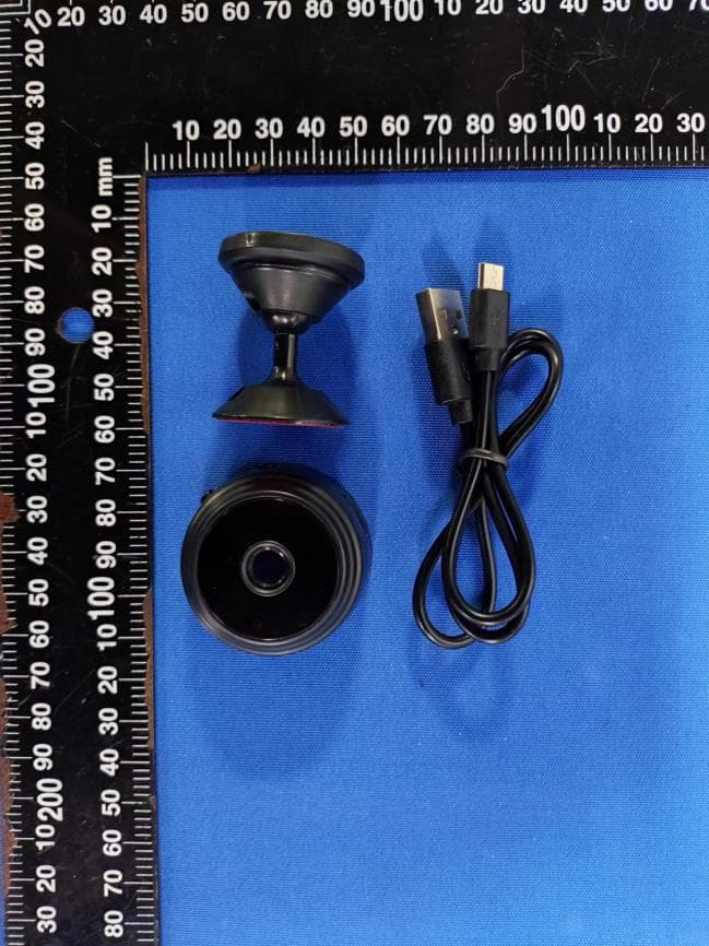
Click to zoom
Application Details
- Equipment Class
- DTS - Digital Transmission System
- Date of Grant
- Jun 07, 2022
- Application Purpose
- Original Equipment
- Date of Application
- Jun 07, 2022
- Equipment Note
- Mini Camera
- Frequency Range
- 2412.00000000 - 2462.00000000
- Country
- China
Documents & Files
Document Text
Text extracted from the exhibit documents filed with the FCC. Open a document above to read the original.
Users Manual
FCC COMPLIANCE STATEMENT: This device complies with part 15 of the FCC Rules. Operation is subject to the following two conditions: (1) This device may not cause harmful interference, and (2) this device must accept any interference received, including interference that may cause undesired operation. Note: This equipment has been tested and found to comply with the limits for a Class B digital device, pursuant to Part 15 of the FCC Rules. These limits are designed to provide reasonable protection against harmful interference in a residential installation. This equipment generates, uses and can radiate radio frequency energy and, if not installed and used in accordance with the instructions, may cause harmful interference to radio communications. However, there is no guarantee that interference will not occur in a particular installation. If this equipment does cause harmful interference to radio or television reception, which can be determined by turning the equipment off and on, the user is encouraged to try to correct the interference by one or more of the following measures: Reorient or relocate the receiving antenna. Increase the separation between the equipment and receiver. Connect the equipment into an outlet on a circuit different from that to which the receiver is connected. Consult the dealer or an experienced radio/TV technician for help. Warning: Changes or modifications to this unit not expressly approved by the part responsible for compliance could void the user’s authority to operate the equipment. FCC Radiation Exposure Statement This equipment must be installed and operated in accordance with provided instructions and the antenna(s) used for this transmitter must be installed to provide a separation distance of at least 20 cm from all persons and must not be co-located or operating in conjunction with any other antenna or transmitter. End-users and installers must be provide with antenna installation instructions and transmitter operating conditions for satisfying RF exposure Product button and indicator description ON/OFF: [ON key, press the button to turn on; press and hold to turn off after turning on] MODE: Press and hold for 5 seconds to restore the factory settings and disconnect the network connected to the monitor Charging indicator (blue):Long light when charging, off when full Work indicator (red):Blinking/long light is on state HD smart life camera use guide Mobile App Installation 1、Download and install 365Cam, IOS is downloaded from Apple Store, Android system is searched in GooglePlay. To facilitate the installation, please scan the QR code below to download 365Cam. If your device cannot connect to GooglePlay, please scan the APK QR code below to download and install. Note: It is recommended to use the browser's own or third-party QR code scanning software to scan and download the App, WeChat sweep function does not support the direct download and installation of App files. (Note: All permissions must be opened when downloading the app) Network indicator (red): 1. slow flash, ap hotspot mode, 2, long light, the device is successfully connected to wifi 3. Fast flashing, device connection failed, wifi password input error Note: When the camera working state is unknown, please reset the camera to restore factory settings (press and hold the camera reset button for more than 5 seconds), the camera reboot after opening the AP mode, wif indicator slow flash (3 seconds flash once). 2. Click "+" to add a device. Click "Device AP Network Configuration". 2. Click "Go to WiFi Configuration" to jump to the WIFI connection page and select ("DGO****×", "DBG****", "HTM****×*","TUT****") WIFI hotspot and connect. 3. After the connection is successful, return to the App, and the device is added successfully. (If the APP does not automatically add the device, you can click Search to add the searched device) front page Video quality: HD Real-time detection rate: 5 up and down about Night vision Clarity full screen Configure external network Video Photo Indicator light sound Replay The second connection method 1. Click "+" to add a device. Click "Device AP Network Configuration". 2,Select WiFi and enter the password, click "Next" and then click " Go to WiFi Configuration" 3. Jump to the WIFI connection page and select ("DGO****×", "DBG****", "HTM****×*", "TUT****") of the WIFI hotspot and connect. Return to the App after successful connection, the device is added successfully. (If the APP does not add the device automatically, you can click Searchto add the searched device) common problem. 1. When using this product for the first time, please fully cha 2. Remote monitoring is not smooth. Please choose the suitable clarity according to the network environment at that time. 3. The memory card does not save video, and it must be formatted the first time the memory card is used. 4. The default password of the camera is 6666. If you forget the user name or password, you can restore the camera to factory settings to get the default user name and password. 5. The camera is restored to its factory settings. Press the reset button of the camera for about 5 seconds until the camera restarts. 6. Why is the image blurry? Remove the protective film of the lens. If it is still not clear, please rotate the camera lens and focus. After focusing, a clear image can be obtained. 7. APP can't search to detect camera/can't configure network, please make sure the device is connected properly and check App Use permission is not restricted. If the application always shows failure, try checking the following items: A. It supports ordinary routers, and public routes that require login page authentication are temporarily not supported. B. When configuring, note that the network name, network password and UID are not incorrect. C. Chinese Wifi names and passwords and special symbols are not supported at the moment. D. Wifi signal that does not support 5G E. The device is not online and the red light is a…
Text truncated - open the document above for the full version.
Cover Letter(s)
Fujian Putian Peiquan Electronic Commerce Co., Ltd. Agent Authorization Company: Fujian Putian Peiquan Electronic Commerce Co., Ltd. Address: Room 504,Building 9,Zhangzhen Village,Gongchen Street,Licheng District,Putian City, Fujian Province Product Name: Mini Camera Model Number(s): A9 Product Description: Mini Camera We authorize MiCOM Labs Inc., 575 Boulder Court, Pleasanton, California 94566, USA, to act on our behalf on all matters concerning the certification of above named equipment. We declare that MiCOM Labs Inc. is allowed to forward all information related to the approval and certification of equipment to the regulatory agencies as required and to discuss any issues concerning the approval application. Any and all acts carried out by MiCOM Labs on our behalf shall have the same effect as acts of our own. Signature: Date: Jun.06,2022 Name: Runyu Xie Title: Manager Company: Fujian Putian Peiquan Electronic Commerce Co., Ltd.
Cover Letter(s)
Fujian Putian Peiquan Electronic Commerce Co., Ltd. Office of Engineering Technology Federal Communications Commission 7435 Oakland Mills Road Columbia, MD 21046 USA Date: June 6, 2022 Subject; Request for Confidentiality FCC ID: 2A66S-A9 To Whom It May Concern, Pursuant to the provisions of the Commission’s rules Title 47 Sections §0.457 and §0.459, we are requesting the Commission to withhold the following attachment(s) as confidential documents from public disclosure indefinitely. These documents contain detailed system and equipment descriptions and are considered as proprietary information in operation of the equipment. The public disclosure of these documents might be harmful to our company and would give competitors an unfair advantage in the market. Schematic Diagram Block Diagram Parts List Operational Description Software Security Requirements for UNII devices In additional to above mentioned documents, in order to comply with the marketing regulations in Title 47 CFR §2.803 and the importation rules in Title 47 CFR §2.1204, while ensuring that business sensitive information remains confidential until the actual marketing of newly authorized devices, we request Short Term Confidentiality of the following attachment(s); External Photos Test Setup Photos Internal Photos User Manual For 45 days, pursuant to Public Notice DA 04-1705. OR For 180 days pursuant to KDB 726920 D01. It is our understanding that all measurement test reports, FCC ID label format and correspondence during the certification review process cannot be granted as confidential documents and this information will be available for public review once the grant of equipment authorization is issued. Sincerely, Signature: Name: Runyu Xie Title: Manager
External Photos
- Page 1 of 7 - Ext Photos - Page 2 of 7 - - Page 3 of 7 -
ID Label/Location Info
Product Name: Mini camera Model No.: A9 Input: 5V1A Manufacturer : Fujian Putian Peiquan Electronic Commerce Co., Ltd. FCC ID: 2A66S-A9 25mm Label location 15mm
Internal Photos
- Page 4 of 7 - Internal photos - Page 5 of 7 - RF Module RF ANT - Page 6 of 7 - - Page 7 of 7 - ------END-----
RF Exposure Info
FCC ID: 2A66S-A9 RF Exposure Evaluation Limits The criteria listed in the following table shall be used to evaluate the environment impact of human exposure to radio frequency (RF) radiation as specified in 1.1307(b) Limits for Maximum Permissible Exposure (MPE) Frequency range (MHz) Electric field strength (V/m) Magnetic field strength (A/m) Power density (mW/cm 2 ) Averaging time (minutes) (A) Limits for Occupational/Controlled Exposures 0.3–3.0 614 1.63 *(100) 6 3.0–30 1842/f 4.89/f *(900/f 2 ) 6 30–300 61.4 0.163 1.0 6 300–1500 f/300 6 1500–100,000 5 6 (B) Limits for General Population/Uncontrolled Exposure 0.3–1.34 614 1.63 *(100) 30 1.34–30 824/f 2.19/f *(180/f 2 ) 30 30–300 27.5 0.073 0.2 30 300–1500 f/1500 30 1500–100,000 1.0 30 f = frequency in MHz Friis transmission formula: Pd = (Pout*G)/(4*pi*r 2 ) Where Pd = power density in mW/cm 2 , Pout = output power to antenna in mW; G = gain of antenna in linear scale, Pi = 3.1416; R = distance between observation point and center of the radiator in cm Pd id the limit of MPE, 1 mW/cm 2 . If we know the maximum gain of the antenna and the total power input to the antenna, through the calculation, we will know the distance r where the MPE limit is reached. Test Procedure Software provided by client enabled the EUT to transmit and receive data at lowest, middle and highest channel individually. FCC ID: 2A66S-A9 Test Result of RF Exposure Evaluation Antenna gain=2.0dBi Mode Output power (dBm) Output power (mW) Numeric antenna gain Power Density at R=20cm (mW/cm 2 ) Limit (mW/cm 2 ) Result 802.11b 12.98 19.86 1.58 0.0062 1.0 PASS 802.11g 16.61 45.81 1.58 0.0144 1.0 PASS 802.11n20 15.48 35.32 1.58 0.0111 1.0 PASS 802.11n40 15.30 33.88 1.58 0.0107 1.0 PASS Then SAR evaluation is not require .
Test Report
Report No.: ET-22050323E Tel: +86 755 85259392 Email: [email protected] No.103, No.10, Phase I, Zone 3, Xinxing Industrial Park, Xinhe, Fuhai Street, Bao'an District, Shenzhen, Guangdong, China TEST REPORT Applicant: Fujian Putian Peiquan Electronic Commerce Co., Ltd. Address of Applicant: Room 504,Building 9,Zhangzhen Village,Gongchen Street,Licheng District,Putian City, Fujian Province Manufacturer/Factory: Fujian Putian Peiquan Electronic Commerce Co., Ltd. Address of Manufacturer: Room 504,Building 9,Zhangzhen Village,Gongchen Street,Licheng District,Putian City, Fujian Province Product Name: Mini Camera Model No.: A9 Trade Mark: MNIEYU FCC ID: 2A66S-A9 Applicable standards: FCC CFR Title 47 Part 15 Subpart C Section 15.247 Date of Test: May. 30, 2022- May.31, 2022 Date of report issued: Jun. 06, 2022 Test Result : PASS * * In the configuration tested, the EUT complied with the standards specified above. Remark: The results shown in this test report refer only to the sample(s) tested , this test report cannot be reproduced, except in full without prior written permission of the company. The report would be invalid without specific stamp of test institute and the signatures of compiler and approver Prepared By Shenzhen ETR Standard Technology Co., Ltd. Address: No.103, No.10, Phase I, Zone 3, Xinxing Industrial Park, Xinhe, Fuhai Street, Bao'an District, Shenzhen, Guangdong, China Compiled by: Reviewed by: Approved by: Project Engineer Project Manager Authorized Signature - Page 2 of 52 - Report No.: ET-22050323E Report Revision History Report No. Description Issue Date ET-22050323E Original Jun. 06, 2022 - Page 3 of 52 - Report No.: ET-22050323E Tel:(86-755) 85259392 Email:[email protected] Web: www.etrlab.cn No.103, No.10, Phase I, Zone 3, Xinxing Industrial Park, Xinhe, Fuhai Street, Bao'an District, Shenzhen, Guangdong, China Contents Page 1. TEST SUMMARY ..................................................................................................................................... 4 2. GENERAL INFORMATION ...................................................................................................................... 5 3.1 GENERAL DESCRIPTION OF EUT ................................................................................................................ 5 3.2 TEST MODE ............................................................................................................................................... 7 3.3 DESCRIPTION OF SUPPORT UNITS .............................................................................................................. 7 3.4 DEVIATION FROM STANDARDS .................................................................................................................... 7 3.5 ABNORMALITIES FROM STANDARD CONDITIONS .......................................................................................... 7 3.6 TEST FACILITY ........................................................................................................................................... 7 3.7 TEST LOCATION ......................................................................................................................................... 7 ADDITIONAL INSTRUCTIONS .............................................................................................................................. 7 3. TEST INSTRUMENTS LIST ..................................................................................................................... 8 4. TEST RESULTS AND MEASUREMENT DATA ...................................................................................... 9 5.1 ANTENNA REQUIREMENT ............................................................................................................................ 9 5.2 CONDUCTED EMISSIONS .......................................................................................................................... 10 5.3 CONDUCTED PEAK OUTPUT POWER ......................................................................................................... 13 5.4CHANNEL BANDWIDTH & 99% OCCUPY BANDWIDTH .................................................................................. 15 5.5 POWER SPECTRAL DENSITY ..................................................................................................................... 19 5.6 BAND EDGES ........................................................................................................................................... 22 Conducted Emission Method .................................................................................................................. 22 Radiated Emission Method ..................................................................................................................... 25 5.7 SPURIOUS EMISSION ................................................................................................................................ 30 Conducted Emission Method .................................................................................................................. 30 Radiated Emission Method ..................................................................................................................... 35 5. TEST SETUP PHOTO ............................................................................................................................ 52 6. EUT CONSTRUCTIONAL DETAILS ..................................................................................................... 52 - Page 4 of 52 - Report No.: ET-22050323E Tel:(86-755) 85259392 Email:[email protected] Web: www.etrlab.cn No.103, No.10, Phase I, Zone 3, Xinxing Industrial Park, Xinhe, Fuhai Street, Bao'an District, Shenzhen, Guangdong, China 1. Test Summary Test Item Section Result Test by Antenna requirement FCC part 15.203/15.247 (c) RSS-Gen §6.8 Pass / AC Power Line Conducted Emission FCC part 15.207 RSS-Gen §8.8 Pass Carr kang Conducted Peak Output Power…
Text truncated - open the document above for the full version.
Test Setup Photos
ET-22050323 Page 1 of 2 Product Name: Mini Camera Test Model No.: A9 Test Setup Photo Radiated Emission ET-22050323 Page 2 of 2 Conducted Emission ------End------
Contact Information
Applicant
Runyu Xie
Technical Contact
Test Firm
Shenzhen ETR Standard Technology Co., Ltd.Smith Chen
[email protected]+86 755-85259392
Technical Specifications
| # | Rule Parts | Frequency Range | Power Output |
|---|---|---|---|
| 1 | 15C | 2.41 GHz - 2.46 GHz | 45.80 mW |