2A69N-XD-W-007wireless charger with phone holder
Shenzhen Xian da Cheng Electronics Co.,Ltd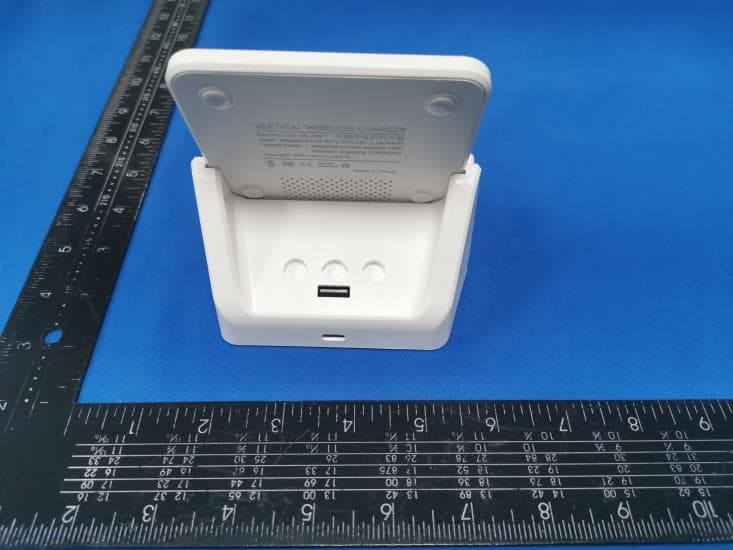
Click to zoom
Application Details
- Equipment Class
- DCD - Part 15 Low Power Transmitter Below 1705 kHz
- Date of Grant
- Jun 07, 2022
- Application Purpose
- Original Equipment
- Date of Application
- Jun 07, 2022
- Equipment Note
- wireless charger with phone holder
- Frequency Range
- 0.11000000 - 0.20500000
- Country
- China
Documents & Files
Document Text
Text extracted from the exhibit documents filed with the FCC. Open a document above to read the original.
External Photos
FCC ID: 2A69N-XD-W-007 XD-W-007 External Photos of the EUT Photo 1 Photo 2 Photo 3 FCC ID: 2A69N-XD-W-007 Photo 4 Photo 5 Photo 6 FCC ID: 2A69N-XD-W-007 Photo 7
ID Label/Location Info
FCC ID: 2A69N-XD-W-007 Label and Location Size: L: 3.0cm*W: 2.0cm Label and Location wireless charger with phone holder Model No.: XD-W-007 FCC ID: 2A69N-XD-W-007
Internal Photos
FCC ID: 2A69N-XD-W-007 XD-W-007 Internal Photos of the EUT Photo 1 Photo 2 Photo 3 FCC ID: 2A69N-XD-W-007 Photo 4 Photo 5 Photo 6 FCC ID: 2A69N-XD-W-007 Photo 7 Photo 8 Photo 9 FCC ID: 2A69N-XD-W-007 Photo 10 Photo 11 Photo 12 Coil Antenna FCC ID: 2A69N-XD-W-007 Photo 13 Photo 14 Photo 15
RF Exposure Info
Page 1 of 5 RF Exposure Evaluation FCC ID: 2A69N-XD-W-007 1 Measuring Standard KDB 680106 D01 RF Exposure Wireless Charging Apps v03 2 Requirements According to the item 5 of KDB 680106 D01v03: Inductive wireless power transfer applications that meet all of the following requirements are excluded from submitting an RF exposure evaluation. (1) Power transfer frequency is less than 1MHz. (2) Output power from each primary coil is less than or equal to 15 watts. (3) The system may consist of more than one source primary coils, charging one or more clients. If more than one primary coil is present, the coil pairs may be powered on at the same time. (4) Client device is placed directly in contact with the transmitter. (5) Mobile exposure conditions only (portable exposure conditions are not covered by this exclusion). (6) The aggregate H-field strengths anywhere at or beyond 15 cm surrounding the device, and 20 cm away from the surface from all coils that by design can simultaneously transmit, and while those coils are simultaneously energized, are demonstrated to be less than 50% of the applicable MPE limit. Limits The criteria listed in the following table shall be used to evaluate the environment impact of human exposure to radio frequency (RF) radiation as specified in 1.1307(b) Limits for Maximum Permissible Exposure (MPE) Page 2 of 5 3 Test Setup 4 Test Procedure 1) The RF exposure test was performed in anechoic chamber. 2) The measurement probe was placed at test distance (15 cm from all sides and 20 cm from the top) which is between the edge of the charger and the geometric center of probe. 3) The highest emission level was recorded and compared with limit as soon as measurement of each points (A, B, C, D, E) were completed. 4) The EUT was measured according to the dictates of KDB 680106 D01v03. Remark:The EUT’s test position A, B, C, D and E is valid for the E and H field measurements. 5 Equipment Approval Considerations The EUT does comply with KDB 680106 D01 as follow table. Requirements of KDB 680106 D01 Yes / No Description Power transfer frequency is less than 1 MHz Yes The device operate in the frequency range 110KHz~205KHz Output power from each primary coil is less than 15 watts Yes The maximum output power for each primary coil is 15W. The system may consist of more than one source primary coils, charging one or more clients. If more than one primary coil is present, the coil pairs may be powered on at the same time. Yes The transfer system includes only one primary coils. Client device is placed directly in contact with the transmitter. Yes Client device is placed directly in contact with the transmitter. Mobile exposure conditions only (portable exposure conditions are not covered by this exclusion). Yes Mobile exposure conditions only The aggregate H-field strengths anywhere at or beyond 15 cm surrounding the device, and 20 cm away from the surface from all coils that by design can simultaneously transmit, and Yes The EUT H-field strengths at 15 cm surrounding the device and 20 cm above the top surface from all simultaneous transmitting coils are demonstrated to be less than 50% of Page 3 of 5 while those coils are simultaneously energized, are demonstrated to be less than 50% of the applicable MPE limit. the MPE limit. 6 Description of the test mode Equipment under test was operated during the measurement under the following conditions: Charging and communication mode Test Modes: Mode 1 AC/DC Adapter (9V/2A) + EUT + iphone (Battery Status: <1%) Record Mode 2 AC/DC Adapter (9V/2A) + EUT + iphone (Battery Status: <50%) Pre-tested Mode 3 AC/DC Adapter (9V/2A) + EUT + iphone (Battery Status: 100%) Pre-tested Mode 4 AC/DC Adapter (5V/2A) + EUT + iphone (Battery Status: <1%) Pre-tested Mode 5 AC/DC Adapter (5V/2A) + EUT + iphone (Battery Status: <50%) Pre-tested Mode 6 AC/DC Adapter (5V/2A) + EUT + iphone (Battery Status: 100%) Pre-tested Note: All test modes were pre-tested, but we only recorded the worst case in this report. 7 Description of Support Units Follow auxiliary equipment(s) test with EUT that provided by the manufacturer or laboratory is listed as follow: Description Manufacturer Model Technical Parameters Certificate Provided by Adapter / GS-551 Input: 100-240V~, 50/60Hz, 0.6A Output:9V/2A, 5V/2A CE/FCC laboratory iPhone Apple 8plus / CE/FCC laboratory Page 4 of 5 8 Test Instruments list Test Equipment Manufacturer Model No. SN. Cal.Date (mm-dd-yy) Cal.Due date (mm-dd-yy) Exposure Level Tester Narda ELT-400 N-0231 2021/11/2 2022/11/01 Magnetic field probe 100cm 2 Narda ELT probe 100cm 2 M0675 2021/11/2 2022/11/01 9 Test Result H-Field Strength at 15 cm from the edges surrounding the EUT and 15cm from the top surface of the EUT Chargin g Battery Level Unit Frequency Range (MHz) Measured E-Field Strength Values (A/m) FCC H-Field Strength 50% Limits (A/m) FCC H-Field Strength Limits (A/m) Test Position A Test Position B Test Position C Test Position D Test Position E 1% uT 0.126 0.293 0.296 0.295 0.280 0.368 -- -- 1% A/m 0.126 0.234 0.237 0.236 0.224 0.294 0.815 1.63 50% uT 0.126 0.215 0.224 0.231 0.229 0.218 -- -- 50% A/m 0.126 0.172 0.179 0.185 0.183 0.174 0.815 1.63 99% uT 0.126 0.148 0.143 0.145 0.144 0.153 -- -- 99% A/m 0.126 0.118 0.114 0.116 0.115 0.122 0.815 1.63 E-Field Strength at 15 cm from the edges surrounding the EUT and 15cm from the top surface of the EUT Chargin g Battery Level Unit Frequency Range (MHz) Measured E-Field Strength Values (V/m) FCC E-Field Strength 50% Limits (V/m) FCC E-Field Strength Limits (V/m) Test Position A Test Position B Test Position C Test Position D Test Position E 1% V/m 0.126 88.218 89.349 88.972 84.448 110.838 307.0 614.0 50% V/m 0.126 64.844 67.483 69.745 68.991 65.598 307.0 614.0 99% V/m 0.126 44.486 42.978 43.732 43.355 45.994 307.0 614.0 Note: V/m= A/m *377 Page 5 of 5 H-Field Strength at 20cm from the top surface of the EUT Charging Battery Level Unit Frequency Range (MHz) Measured E-Field Strength Values (A/m) FCC…
Text truncated - open the document above for the full version.
Test Report
Shenzhen CTA Testing Technology Co., Ltd. Room 106, Building 1, Yibaolai Industrial Park, Qiaotou Community, Fuhai Street, Bao’an District, Shenzhen, China Shenzhen CTA Testing Technology Co., Ltd. Room 106, Building 1, Yibaolai Industrial Park, Qiaotou Community, Fuhai Street, Bao’an District, Shenzhen, China Tel:+86-755 2322 5875 E-mail:[email protected] Web:http://www.cta-test.cn FCC PART 15 SUBPART C TEST REPORT Report Reference No. ..................... : FCC ID. ............................................ : CTA22052400101 2A69N-XD-W-007 Compiled by ( position+printed name+signature) .. : File administrators Kevin Liu Supervised by ( position+printed name+signature) .. : Project Engineer Kevin Liu Approved by ( position+printed name+signature) .. : RF Manager Eric Wang Date of issue ..................................... : May 27, 2022 Testing Laboratory Name ..............: Shenzhen CTA Testing Technology Co., Ltd. Address ............................................ : Room 106, Building 1, Yibaolai Industrial Park, Qiaotou Community, Fuhai Street, Bao‘an District, Shenzhen, China Applicant’s name ............................ : Shenzhen Xian da Cheng Electronics Co.,Ltd Address ............................................ : Kang shi da Industrial Zone 7f, No.113 Li xin Road, Nan wan Street, Long gang District, Shenzhen, China Test specification ...........................: Standard ........................................... : FCC Rules and Regulations Part 15 Subpart C (Section 15.209), ANSI C63.10: 2013 Shenzhen CTA Testing Technology Co., Ltd. All rights reserved. This publication may be reproduced in whole or in part for non-commercial purpses as long as the Shenzhen CTA Testing Technology Co., Ltd. is acknowledged as copyright owner and source of the material. Shenzhen CTA Testing Technology Co., Ltd. takes no responsibility for and will not assume liability for damages resulting from the reader's interpretation of the reproduced material due to its placement and context. Test item description .....................: wireless charger with phone holder Trade Mark ....................................... : N/A Manufacturer .................................... : Shenzhen Xian da Cheng Electronics Co.,Ltd Model/Type reference....................... : XD-W-007 Listed Models .................................. : XD-W-001, XD-W-002, XD-W-003, XD-W-005, XD-W-006, XD-W- 008, XD-W-0010, XD-W-012, XD-W-015, XD-W-016 Modulation Type ............................... : ASK Operation Frequency ........................ : From 110KHz~205KHz Rating ............................................... : DC 5V/9V From External circuit Output: Wireless Charging: 15M(MAX) Result................................................ : PASS Report No.: CTA22052400101 Page 2 of 26 Shenzhen CTA Testing Technology Co., Ltd. Room 106, Building 1, Yibaolai Industrial Park, Qiaotou Community, Fuhai Street, Bao’an District, Shenzhen, China Tel:+86-755 2322 5875 E-mail:[email protected] Web:http://www.cta-test.cn T E S T R E P O R T Equipment under Test : wireless charger with phone holder Model /Type : XD-W-007 Listed Models : XD-W-001, XD-W-002, XD-W-003, XD-W-005, XD-W-006, XD-W-008, XD-W-0010, XD-W-012, XD-W-015, XD-W-016 Applicant : Shenzhen Xian da Cheng Electronics Co.,Ltd Address : Kang shi da Industrial Zone 7f, No.113 Li xin Road, Nan wan Street, Long gang District, Shenzhen, China Manufacturer : Shenzhen Xian da Cheng Electronics Co.,Ltd Address : Kang shi da Industrial Zone 7f, No.113 Li xin Road, Nan wan Street, Long gang District, Shenzhen, China Test Result: PASS The test report merely corresponds to the test sample. It is not permitted to copy extracts of these test result without the written permission of the test laboratory. Report No.: CTA22052400101 Page 3 of 26 Shenzhen CTA Testing Technology Co., Ltd. Room 106, Building 1, Yibaolai Industrial Park, Qiaotou Community, Fuhai Street, Bao’an District, Shenzhen, China Tel:+86-755 2322 5875 E-mail:[email protected] Web:http://www.cta-test.cn Contents 1 T E S T S T A N D A R D S ................................................................. 4 2 S U M M A R Y ............................................................................ 5 2.1 General Remarks 5 2.2 Product Description 5 2.3 Description of the test mode 5 2.4 Special Accessories 5 2.5 Modifications 5 3 T E S T E N V I R O N M E N T .............................................................. 6 3.1 Address of the test laboratory 6 3.2 Test Facility 6 3.3 Environmental conditions 6 3.4 Summary of measurement results 7 3.5 Statement of the measurement uncertainty 7 3.6 Equipments Used during the Test 8 4 T E S T C O N D I T I O N S A N D R E S U L T S ............................................. 9 4.1 AC Power Conducted Emission 9 4.2 Radiated Emission 12 4.3 The 20dB bandwidth 16 4.4 Antenna Requirement 17 5 T E S T S E T U P P H O T O S O F T H E E U T ......................................... 18 6 PH O T O S O F T H E E U T ........................................................... 19 Report No.: CTA22052400101 Page 4 of 26 Shenzhen CTA Testing Technology Co., Ltd. Room 106, Building 1, Yibaolai Industrial Park, Qiaotou Community, Fuhai Street, Bao’an District, Shenzhen, China Tel:+86-755 2322 5875 E-mail:[email protected] Web:http://www.cta-test.cn 1 T E S T S T A N D A R D S The tests were performed according to following standards: FCC Rules and Regulations Part 15 Subpart C (Section 15.207): Conducted limits. FCC Rules and Regulations Part 15 Subpart C (Section 15.209): Radiated emission limits; general requirements. ANSI C63.10: 2013: American National Standard for Testing Unlicensed Wireless Devices Report No.: CTA22052400101 Page 5 of 26 Shenzhen CTA Testing Technology Co., Ltd. Room 106, Building 1, Yibaolai Industrial Park, Qiaotou Community, Fuhai Street, Bao’an District, Shenzhen, China Tel:+86-755 2322 5875 E-mail:[email protected] Web:http://www.cta-test.cn 2 S U M M A R Y 2.1 General R…
Text truncated - open the document above for the full version.
Test Setup Photos
FCC ID: 2A69N-XD-W-007 XD-W-007 Test Setup Photos of the EUT conduction radiation
Contact Information
Applicant
lingling Wang
Test Firm
SHENZHEN CTA TESTING TECHNOLOGY CO., LTD.Eric Wang
[email protected]+86 755 2322 5875
Technical Specifications
| # | Rule Parts | Frequency Range | Power Output |
|---|---|---|---|
| 1 | 15C | 0.11 MHz - 0.205 MHz | - |