2A6BN-GX5DLaser Timer
Hangzhou Ganxin Electronic Co.,Ltd.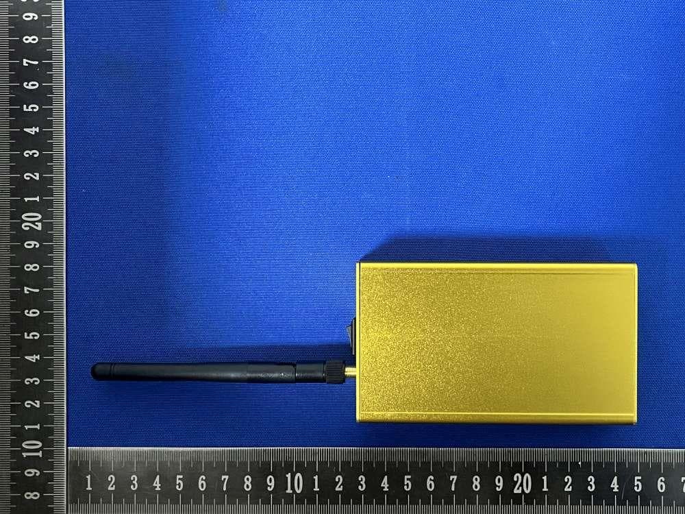
Click to zoom
Application Details
- Equipment Class
- DSC - Part 15 Security/Remote Control Transmitter
- Date of Grant
- Mar 23, 2026
- Application Purpose
- Original Equipment
- Equipment Note
- Laser Timer
- Frequency Range
- 433.92000000 - 433.92000000
- Country
- China
Documents & Files
Document Text
Text extracted from the exhibit documents filed with the FCC. Open a document above to read the original.
Users Manual
Multi-function Visual Laser Timer Instruction Manual 1. Power On: Turn on the power switch on the side of the timer. The display screen will show "88.888", then display a number "XXX", where "XXX" indicates the current remaining battery percentage. After 2 seconds, it will display "- X X - -", indicating the current timing mode of the timer. After another 2 seconds, the display will emit a laser, entering the operational state. 2. Mode Selection: After powering on, you can modify the mode settings on the timer. Press and hold the metal button on the left side of the timer for about 3 seconds to enter the mode setting state. Tap this metal button to cycle through the timer modes: "1, 2, 3, 4, 5, 6, 7, L1, L2, L3, F1, F2, F3". After selecting the desired mode, press the power switch to turn off the timer, then turn it on again. The timer will now operate in the selected timing mode. 3. Alignment: Adjust the position of the timer and the reflector so that the laser emitted by the timer shines onto the reflector. The red indicator light will stay on when properly aligned. If not aligned, the red indicator light will flash. 4. Usage: Modes 1-7:Used for shuttle run (single unit) or dual-unit mode. Timing starts as soon as any unit is triggered. After triggering, the display shows the remaining count. Timing stops after the final trigger. Press the (detector's button) side button to clear the time value and restart. L1 Mode:The timer's laser detection function is disabled. The detector controls the timing: trigger to start timing, trigger again to stop timing, trigger again to reset the time to zero and restart timing. L2 Mode:Timing can only be started by triggering the detector. If triggered again before the timer is triggered, the time display resets (the internal timer continues running). If the detector is triggered again at this point, it resets and restarts timing. When the timer is triggered, it displays the elapsed time from start until the timer was triggered, showing the current triggered time value. If the detector's laser beam is triggered at this point, it resets and restarts. L3 Mode:Whether triggered by the detector or the timer, the first trigger starts timing, the second trigger stops timing, and a subsequent trigger resets and restarts timing. F1 Mode:Single timer mode. Trigger to start timing. The next trigger records the time elapsed from the start to that point. Subsequent triggers display the cumulative time from the start. F2 Mode:Single timer mode. Trigger to start timing. The next trigger displays the time elapsed from start to that trigger. The next trigger displays the time interval between the two triggers. F3 Mode:Used for channel switching. Set to F3, and upon next power-on, it will enter channel selection. After selection, turn on the detector; it will automatically sync to the channel and then power off automatically. After the timer syncs, turning it off will make it display Mode 1. Mode F3: Changing the Timing System Channel (Use with Caution) When two sets of our products using the same channel are used in the same venue, they may interfere with each other. You can change the channel for one of the systems. During operation, all devices must be powered off first to prevent misoperation. Select F3 in the mode settings. Power off and then on again. After displaying F3, the timer will show two digits "0-X--". The "0" represents the screen ID of the detector about to be added, and the following number indicates the current channel used by this timer set. Tap the "Side Button" touch key on the left side of the timer to cycle through channels "0-9". After selecting the desired channel, power on or connect the devices that need their channel changed, one by one. They will sync sequentially based on the boot order, and the screen ID will increase accordingly. Detectors will automatically power off after the channel is modified. Devices that do not need channel modification must not be powered on. Remember this! After modifying all devices, power off the main unit. The channel change operation is now complete. Charging Indicator: After inserting the adapter, the charging indicator light will turn red. When fully charged, the indicator light will change from red to green. FCC WARNING This device complies with part 15 of the FCC Rules. Operation is subject to the following two conditions: (1) This device may not cause harmful interference; (2) this device must accept any interference received, including interference that may cause undesired operation. Note: This equipment has been tested and found to comply with the limits for a Class B digital device, pursuant to part 15 of the FCC Rules. These limits are designed to provide reasonable protection against harmful interference in a residential installation. This equipment generates, uses and can radiate radio frequency energy and, if not installed and used in accordance with the instructions, may cause harmful interference to radio communications. However, there is no guarantee that interference will not occur in a particular installation. If this equipment does cause harmful interference to radio or television reception, which can be determined by turning the equipment off and on, the user is encouraged to try to correct the interference by one or more of the following measures: —Reorient or relocate the receiving antenna. —Increase the separation between the equipment and receiver. —Connect the equipment into an outlet on a circuit different from that to which the receiver is connected. —Consult the dealer or an experienced radio/TV technician for help. Note: The Grantee is not responsible for any changes or modifications not expressly approved by the party responsible for compliance. such modifications could void the user's authority to operate the equipment. The device has been evaluated to meet general RF exposure requirement. This equipment complies with FCC's RF radiation exposure limits set forth for an uncontrol…
Text truncated - open the document above for the full version.
Attestation Statements
Hangzhou Ganxin Electronics Co., Ltd. U.S. Agent Letter of Attestation To: Federal Communications Commission 7435 Oakland Mills Road, Columbia, MD 21046, USA Date: March 18, 2026 Ref: Attestation Statement – Part 2.911(d)(7) filing FCC ID: 2A6BN-GX5D Hangzhou Ganxin Electronics Co., Ltd.(“the applicant”) certifies that, as of the date of the filing of the application, CLF Import and Export Limited (“the agent”) is our designated U.S. agent for service of process for the above reference FCC ID. The applicant accepts to maintain an agent for service of process in the United States for no less than one year after either the grantee has permanently terminated all marketing and importation of the applicable equipment within the U.S., or the conclusion of any Commission-related administrative or judicial proceeding involving the equipment, whichever is later. The applicant further acknowledges it is our responsibility to inform the FCC whenever the agent information changes. CLF Import and Export Limited ("the agent) understand it is the agent's obligation to accept service of process in the United States for matters related to the applicable equipment, and at the physical U.S. address and email address. Designated U.S. Agent Company Name: CLF Import and Export Limited FRN: 0033489683 Address: 1312 17th Street #692, Denver, CO 80202, United States Signature: Contact Person: David Chen Tel: +1 949 254 2565 Email: [email protected] Applicant Company Name: Hangzhou Ganxin Electronics Co., Ltd. FRN: 0032234544 Address: 2# building, 22 Zhiren Rd. Puyan Street Binjiang District, Hangzhou, Zhejiang Hangzhou, Zhejiang China. Signature: Contact Person: mei qin song Tel: 15957153517 Email: [email protected]
Attestation Statements
Rev 1/26/2023 (Hangzhou Ganxin Electronics Co., Ltd.) Federal Communications Commission Authorization and Evaluation Division 7435 Oakland Mills Road Columbia, MD 21046 USA Date: March 18, 2026 Ref: Attestation Statements Part 2.911(d)(5)(i) Filing FCC ID: 2A6BN-GX5D [Hangzhou Ganxin Electronics Co., Ltd.] certifies that the equipment for which authorization is sought is not “covered” equipment prohibited from receiving an equipment authorization pursuant to section 2.903 of the FCC rules. [Hangzhou Ganxin Electronics Co., Ltd.] certifies that the equipment for which authorization is sought does not include cybersecurity or anti-virus software produced or provided by Kaspersky Lab, Inc. or any of its successors and assignees, including equipment with integrated Kaspersky Lab, Inc. (or any of its successors and assignees) cybersecurity or anti-virus software pursuant to DA-24-886 and KDB 986446 D01 Covered Equipment Guidance section B(2a). Device is inherently compliant based on hardware limitations or software controls. or A Software Bill of Materials (SBOM) is provided to the TCB for review, and The end-user or third parties cannot install additional software on this device. Sincerely, (mei qin song) Rev 1/26/2023 (Hangzhou Ganxin Electronics Co., Ltd.) Federal Communications Commission Authorization and Evaluation Division 7435 Oakland Mills Road Columbia, MD 21046 USA Date: March 18, 2026 Ref: Attestation Statements Part 2.911(d)(5)(ii) Filing FCC ID: 2A6BN-GX5D [Hangzhou Ganxin Electronics Co., Ltd.] certifies that, as of the date of the filing of the application, the applicant is not identified on the Covered List (as a specifically named entity or any of its subsidiaries or affiliates) as an entity producing “covered” equipment. Sincerely, (mei qin song)
Cover Letter(s)
Hangzhou Ganxin Electronics Co., Ltd. Office of Engineering Technology Federal Communications Commission 7435 Oakland Mills Road Columbia, MD 21046 USA Date: March 18, 2026 Subject; Request for Confidentiality FCC ID: 2A6BN-GX5D To Whom It May Concern, Pursuant to the provisions of the Commission’s rules Title 47 Sections §0.457 and §0.459, we are requesting the Commission to withhold the following attachment(s) as confidential documents from public disclosure indefinitely. These documents contain detailed system and equipment descriptions and are considered as proprietary information in operation of the equipment. The public disclosure of these documents might be harmful to our company and would give competitors an unfair advantage in the market. Schematic Diagram Block Diagram Parts List Operational Description Tune-up Procedure Software Security Requirements for UNII devices In additional to above mentioned documents, in order to comply with the marketing regulations in Title 47 CFR §2.803 and the importation rules in Title 47 CFR §2.1204, while ensuring that business sensitive information remains confidential until the actual marketing of newly authorized devices, we request Short Term Confidentiality of the following attachment(s); External Photos Test Setup Photos Internal Photos User Manual For 45 days, pursuant to Public Notice DA 04-1705. OR For 180 days pursuant to KDB 726920 D01. It is our understanding that all measurement test reports, FCC ID label format and correspondence during the certification review process cannot be granted as confidential documents and this information will be available for public review once the grant of equipment authorization is issued. Sincerely, Signature: Name: mei qin song Title: The general manager
Cover Letter(s)
Hangzhou Ganxin Electronics Co., Ltd. Date: March 18, 2026 Product Model Number: GX5D-1.8 Track timer FCC ID: 2A6BN-GX5D To whom it may concern, Re: Product Certification Representative Authorization Letter We authorize QAI Laboratories Ltd. 3980 North Fraser Way, Burnaby B.C. Canada V5J 5K5 to act on our behalf on all matters concerning the above named equipment. This shall include the following: • Testing • Approval applications and procedures We declare that QAI Laboratories Ltd. is allowed to forward all information related to the approval project to the applied certification body and to the notification entities and to discuss any issues concerning the approval application. Any and all acts carried out by QAI Laboratories Ltd. on our behalf shall have the same effect as acts of our own. Contact Listed on FCC Wesbite Signature: By: mei qin song Title: The general manager Email: [email protected] Telephone: 15957153517 On behalf of: Hangzhou Ganxin Electronics Co., Ltd.
External Photos
Report No: SSP25100369-1E FCC ID: 2A6BN-GX5D Annex of Test Report Annex A. EUT External Photos Model: GX5D-1.8 Track timer EUT View 1 EUT View 2 Report No: SSP25100369-1E FCC ID: 2A6BN-GX5D Annex of Test Report EUT View 3 EUT View 4 Report No: SSP25100369-1E FCC ID: 2A6BN-GX5D Annex of Test Report EUT View 5 EUT View 6 Report No: SSP25100369-1E FCC ID: 2A6BN-GX5D Annex of Test Report EUT View 7 EUT View 8
ID Label/Location Info
Report No: SSP25100369-1E FCC ID: 2A6BN-GX5D Annex of Test Report Annex D. Label and Information FCC Label Sample FCC Labe Size: 3cm x 2cm FCC Label Specifications Text is Black in color and is justified. Labels are printed in indelible ink on permanent adhesive backing or silk-screened onto the EUT or shall be affixed at a conspicuous location on the EUT. Where the EUT is constructed in two or more sections connected by wires and marketed together, the above statement is required to be affixed only to the main control unit. When the EUT is so small or for such use that it is not practicable to place the statement on it, the above information shall be placed in a prominent location in the instruction manual or pamphlet supplied to the user or, alternatively, shall be placed on the container in which the device is marketed. FCC Label Location Label Location
Internal Photos
Report No: SSP25100369-1E FCC ID: 2A6BN-GX5D Annex of Test Report Annex B. EUT Internal Photos Model: GX5D-1.8 Track timer EUT Internal View 1 EUT Internal View 2 Glue stick antenna Report No: SSP25100369-1E FCC ID: 2A6BN-GX5D Annex of Test Report EUT Internal View 3 EUT Internal View 4 Report No: SSP25100369-1E FCC ID: 2A6BN-GX5D Annex of Test Report EUT Internal View 5 EUT Internal View 6
RF Exposure Info
FCC ID: 2A6BN-GX5D RF Exposure Evaluation According to KDB 447498 D04 RF Exposure Procedures and Equipment Authorization Policies for Mobile and Portable Devices part 2.1.2, a single RF source is exempt RF device (from the requirement to show data demonstrating compliance to RF exposure limits, as previously mentioned) if the available maximum time-averaged power is no more than 1mW, regardless of separation distance. This exemption applies to all operating configurations and exposure conditions, for the frequency range 100 kHz to 100 GHz, regardless of fixed, mobile, or portable device exposure conditions. This is a standalone exemption, and it cannot be applied in conjunction with any other test exemption. The result is rounded to one decimal place for comparison Here, The device has been evaluated to meet general RF exposure requirement. The device can be used in portable exposure condition without restriction. Frequency (MHz) Power (dBuV/m) Power (dBm) Power (mW) Limit (mW) 433.92 87.82 -7.38 0.18 1 Notes: 87.82dBuV/m-95.2=-7.38dBm 0.18mW<1mW, so a SAR test is not required.
Test Report
Page 1 of 2 1. General Information 1.1 Antenna Information Manufacturer: Hangzhou Ganxin Electronics Co., Ltd Address of Manufacturer: 2# building, 22 Zhiren Rd. Puyan Street Binjiang District, Hangzhou, Zhejiang Hangzhou, Zhejiang China. Product Name: 433.92MHz Antenna Model Name: GX5D-1.8 Track timer Frequency Range: 433.92MHz Type of Antenna: Glue stick antenna Antenna Gain: 0dBi (Max.) Impedance: 50 ohm Antenna View: Length * Width (10.9cm * 1cm) Page 2 of 2 2. Antenna Specification information 2.1 Gain Frequency Peak Gain (dBi) Polarity 433.92MHz 0 Horizontal 433.92MHz -1.56 Vertical 2.2 Radiation Pattern View
Test Report
Report No: SSP25100369-1E FCC Test Report Page 1 of 25 FCC TEST REPORT FCC ID: 2A6BN-GX5D Report No. : SSP25100369-1E Applicant : Hangzhou Ganxin Electronics Co., Ltd. Product Name : Laser Timer Model Name : GX5D-1.8 Track timer Test Standard : FCC Part 15.231 Date of Issue : 2026-03-18 Shenzhen CCUT Quality Technology Co., Ltd. 1F, Building 35, Changxing Technology Industrial Park, Yutang Street, Guangming District, Shenzhen, Guangdong, China; (Tel.:+86-755-23406590 website: www.ccuttest.com) This test report is limited to the above client company and the product model only. It may not be duplicated without prior permitted by Shenzhen CCUT Quality Technology Co., Ltd. Report No: SSP25100369-1E FCC Test Report Page 2 of 25 Test Report Basic Information Applicant..................................: Hangzhou Ganxin Electronics Co., Ltd Address of Applicant...............: 2# building, 22 Zhiren Rd. Puyan Street Binjiang District, Hangzhou, Zhejiang Hangzhou, Zhejiang China. Manufacturer..........................: Hangzhou Ganxin Electronics Co., Ltd Address of Manufacturer........: 2# building, 22 Zhiren Rd. Puyan Street Binjiang District, Hangzhou, Zhejiang Hangzhou, Zhejiang China. Product Name.........................: Laser Timer Brand Name.............................: GANXIN Main Model..............................: GX5D-1.8 Track timer Series Models..........................: - Test Standard..........................: FCC Part 15 Subpart C ANSI C63.4-2014 ANSI C63.10-2020 Date of Test .............................: 2025-11-03 to 2025-11-17 Test Result...............................: PASS Tested By ................................: (Colin Chen) Reviewed By............................: (Lorzix Luo) Authorized Signatory............: (Lahm Peng) Note : This test report is limited to the above client company and the product model only. It may not be duplicated without prior permitted by Shenzhen CCUT Quality Technology Co., Ltd.. All test data presented in this test report is only applicable to presented test sample. Report No: SSP25100369-1E FCC Test Report Page 3 of 25 CONTENTS 1. General Information ....................................................................................................................................................5 1.1 Product Information .............................................................................................................................................5 1.2 Test Setup Information..........................................................................................................................................5 1.3 Compliance Standards ...........................................................................................................................................6 1.4 Test Facilities ........................................................................................................................................................6 1.5 List of Measurement Instruments ..........................................................................................................................7 1.6 Measurement Uncertainty .....................................................................................................................................7 2. Summary of Test Results .............................................................................................................................................8 3. Antenna Requirement .................................................................................................................................................9 3.1 Standard and Limit................................................................................................................................................9 3.2 Test Result ............................................................................................................................................................9 4. Conducted Emissions ................................................................................................................................................ 10 4.1 Standard and Limit.............................................................................................................................................. 10 4.2 Test Procedure.................................................................................................................................................... 10 4.3 Test Data and Results .......................................................................................................................................... 11 5. Radiated Emissions ................................................................................................................................................... 14 5.1 Standard and Limit.............................................................................................................................................. 14 5.2 Test Procedure.................................................................................................................................................... 14 5.3 Test Data and Results .......................................................................................................................................... 16 6. Occupied Bandwidth ................................................................................................................................................. 20 6.1 Standard and Limit.............................................................................................................................................. 20 6.2 Test Procedure.................................................................................................................................................... 20 6.3 Test Data and Results .......................................................................................................................................... 20 …
Text truncated - open the document above for the full version.
Test Setup Photos
Report No: SSP25100369-1E FCC ID: 2A6BN-GX5D Annex of Test Report Annex C. Test Photos Conducted Emission Test View 1 Radiated Emission Test View Below 1GHz Report No: SSP25100369-1E FCC ID: 2A6BN-GX5D Annex of Test Report Radiated Emission Test View Above 1GHz
Contact Information
Applicant
mei qin song(The general manager)
[email protected]Fax: 0571-28886626
Technical Contact
Test Firm
Shenzhen CCUT Quality Technology Co., Ltd.Lahm Peng
Technical Specifications
| # | Rule Parts | Frequency Range | Power Output |
|---|---|---|---|
| 1 | 15.231 | 433.92 MHz - 433.92 MHz | - |