2A6BYAKES-11SICapsule
ANKON Technologies Co., Ltd.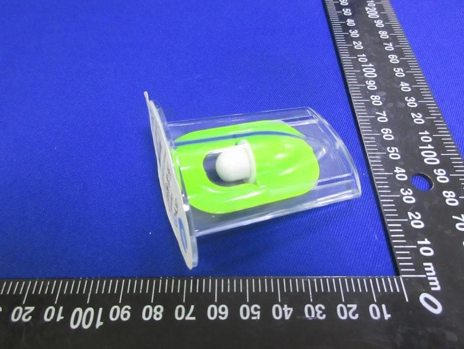
Click to zoom
Application Details
- Equipment Class
- DTS - Digital Transmission System
- Date of Grant
- Jul 14, 2022
- Application Purpose
- Original Equipment
- Date of Application
- Jun 13, 2022
- Equipment Note
- Capsule
- Frequency Range
- 905.00000000 - 925.00000000
- Company
- ANKON Technologies Co., Ltd.
- Country
- China
Documents & Files
Document Text
Text extracted from the exhibit documents filed with the FCC. Open a document above to read the original.
Users Manual
NaviCamSmallBowelCapsule EndoscopySystem UserManual ANKONTechnologiesCo.,Ltd. AKQWO-YF-018 RevisionA/1 NaviCamSmallBowelCapsuleEndoscopySystem UserManualPag e| 2 ANKONTechnologiesCo.,Ltd.AKQWO-YF-018RevA/1 CopyrightStatement: TheownershipoftheUserManualbelongstoANKONTechnologiesCo.,Ltd.,anditshouldnotbe distributed or reproduced by any means or in any form without prior written permission by ANKON Technologies Co., Ltd.. The User Manual is protected by copyright, and all rights are reserved. ANKON Technologies Co., Ltd. reserves the right to change the User Manual and the products as described herein. Equipment specifications are subject to change without prior notification. Any information contained in the User Manual is not to be considered a proposal, guarantee,commitmentorcontractualconditions. Warranty ANKONTechnologiesCo.,Ltd.assuresthatallpartsintheNaviCamSmallBowelCapsule EndoscopySystemarewell-designed,manufactured,packedandtestedforpreventionofdefects, andassumesnoresponsibilityforanyaccident,loss,damageorcostincreasedirectlyor indirectlyresultingfromuseoftheESViewplatform.ANKONTechnologiesCo.,Ltd.willrepair orreplacepartswithinthewarrantyperiod,whilecustomerisresponsibleforallotheritems includingnormalwearandteamoranythingthatisoutofthecontrolofANKONTechnologies Co.,Ltd.,includingbutnotlimitedtooperation,storage,cleaning,misuse,abuse,patient treatmentordiagnosis.Thiswarrantyreplacesanyotherwarrantieswhichmayhavebeen impliedinverbalordocumentedform. ModificationsbyUserorThirdParty Anyandallmodificationstotheproductwhicharenotexpresslyapprovedinwritingby ANKONTechnologiesCo.,Ltd.willvoidthiswarrantyinitsentirety. Manufacturer:ANKONTechnologiesCo.,Ltd. Address:B3-2,B3-3,D3-4Biolake,No.666,Hi-TechRoad,EastLakeNewTechnology DevelopmentZone,Wuhan,430075Hubei,China CAUTION: USFederallawrestrictsthisdevicetosalebyorontheorderofaphysician. NaviCamSmallBowelCapsuleEndoscopySystem UserManualPag e| 3 ANKONTechnologiesCo.,Ltd.AKQWO-YF-018RevA/1 TABLEOFCONTENTS CHAPTER1: ....................................................................................................................... INTRODUCTION5 1.1 I MPORTANT I NFORMATION ................................................................................................................... 5 1.2 A BOUT N AVI C AM S MALL B OWEL C APSULE E NDOSCOPY S YSTEM ........................................................... 5 1.2.1Capsule(AKES-11SW/AKES-11SI) ....................................................................................... 6 1.2.2DataRecorder ......................................................................................................................... 7 1.2.3Locator ..................................................................................................................................... 9 1.2.4ESViewSoftware ................................................................................................................... 10 1.3 S UMMARYOF C LINICAL P ERFORMANCE .............................................................................................. 10 CHAPTER2: .................................................. INDICATIONS,CONTRAINDICATIONSANDWARNINGS14 2.1 I NDICATIONS ..................................................................................................................................... 14 2.2 C ONTRAINDICATIONS ......................................................................................................................... 14 2.3 A DVERSE E VENTS ............................................................................................................................... 14 2.4 W ARNINGS ........................................................................................................................................ 14 CHAPTER3: .................................................................. ESVIEWSOFTWAREOPERATIONINITIATION17 3.1 I NSTALLATION ................................................................................................................................... 17 3.2 U NINSTALLATION ............................................................................................................................... 20 3.3 B ASIC S OFTWARE O PERATION ............................................................................................................ 21 3.4 S OFTWARE S TARTUP .......................................................................................................................... 22 3.4.1First-timeStartup ................................................................................................................. 22 3.4.2RegularStartup ..................................................................................................................... 23 CHAPTER4: ........................................................... ESVIEWSOFTWAREOPERATIONINSTRUCTIONS25 4.1 P ATIENT C HECK - IN ............................................................................................................................ 25 4.2 R EAL T IME V IEWINGIN R TDISPLAY I NTERFACE .................................................................................. 26 4.2.1AccessRtdisplay ................................................................................................................... 26 4.2.2FunctionsofButtonsintheToolbar .................................................................................. 27 4.2.3RtdisplayImageZoom-inandOut ..................................................................................... 28 4.2.4DataRecorderStatusIndicator .......................................................................................... 28 4.3 D ATA E XPORT .................................................................................................................................... 29 4.4 I MAGE B ROWSING ,P ROCESSING , AND E DITING ,P RO S CANMODE ......................................................... 31 4.4.1 OpenV…
Text truncated - open the document above for the full version.
Users Manual
NaviCamSmallBowelCapsuleEndoscopySystem UserManualPag e| 50 ANKONTechnologiesCo.,Ltd.AKQWO-YF-018RevA/1 2. Click,whenthebuttoniconchangesto,thefilterbrowsingmodewillbeactivated (Figure4-39).Inthismode,thesoftwaredisplaysonlytaggedorcapturedimagesforfurther screening. Figure4-39:FilterBrowsingMode 4.4.9 OptionSetting 1. Inthemainsoftwareinterface,select“Tool”“Option”toaccesstheoptionsettinginterface (Figure4-40). NaviCamSmallBowelCapsuleEndoscopySystem UserManualPag e| 51 ANKONTechnologiesCo.,Ltd.AKQWO-YF-018RevA/1 Figure4-40:OptionSettingInterface 2. Inthe“Department”area,fillinthedepartmentinformation,whichwillappearinthecase report. 3. Inthe“Exportpath”area,choosethepathsforexportedvideofilesandrawdata.Ifthe “DeleteRAWfilesafterexported”optionischeckedandthedataisexportedtovideofile usingthedirectexportmode,thenafterexport,therelatedRAWfilesintheRAWfilepath willbeautomaticallydeletedtosavespace. 4. Inthe“Others”area,ifthe“Displayimagepreviewwhenmousehoversoverthetime progressbar”optionischecked,asthemousemovesovertheprogressbar,thepreviewof theimagecorrespondingtothemouselocationwillbedisplayedinafloatingwindowifthe mousestopsforabout1second,asshowninFigure4-41. NaviCamSmallBowelCapsuleEndoscopySystem UserManualPag e| 52 ANKONTechnologiesCo.,Ltd.AKQWO-YF-018RevA/1 Figure4-41:ImagePreview 5. Ifthe“Addpatientinfowhensaveimagesormp4videos”optionischecked,thepatient informationwillbeaddedtotheupperleft,upperright,andlowerleftcornersofthesave image,asshowninFigure4-42.Leftclicktosavethecurrentimage.Rightclickto openthefolderwherethesavedimagesarelocated.Ifthe“Openthefindingfilewhen openingthevideoimages”optionischecked,thentheusercanopenthelastsavedfinding filewhenopeningthepatientvideo. Figure4-42:SavedImageShowingPatientInformation 4.4.10NaviCamProScan NaviCamProScanfeaturecontainstwomainfunctions: –Imagesofsuspectedpositivelesions(includingfourkinds:lymphangiectasia 、 Inflammation/erosion/bleeding/ulcer 、 polyp/bulgingorlymphoidfollicularhyperplasia anddiverticulum)areautomaticallymarked,andtheimagepositionismarkedinredon NaviCamSmallBowelCapsuleEndoscopySystem UserManualPag e| 53 ANKONTechnologiesCo.,Ltd.AKQWO-YF-018RevA/1 theimageribbon. –The esophagus, stomach, and small intestine are automatically segmented for the digestive tract image, and different digestive tract segments are marked with different colorsontheimageribbon. ThisNaviCamProScanfeaturecanonlybeusedwhenthefollowing3conditionsaremet: 1) Checkthe"AllowNaviCamProScan(requiresrestart)"option,andrestarttheESView softwaretotakeeffect,asshowninFigure4-43. Figure4-43:ProScanFeatureOption 2) Use"Exportandconvertdataintovideofile"or"ConvertexistingRAWfileintovideofiles"to exportdata.Afterexporting,check"RecognizeProgress"as100%and"RecognizeStatus"as NaviCamSmallBowelCapsuleEndoscopySystem UserManualPag e| 54 ANKONTechnologiesCo.,Ltd.AKQWO-YF-018RevA/1 "Recognitionsuccess"intheCaseManagementcaselist,asshowninFigure4-44. Figure4-44:RecognizeProgress 3)Ifsuspectedpositivelesionsarefound. 1. IftheNaviCamProScanfunctionisnotenabled,therewillbenoProScanicondisplayed onthemaininterfaceofESView.IftheNaviCamProScanfunctionisenabledbutthedatahas notbeenautomaticallyidentifiedandprocessedbyProScan,theProScaniconcanbe displayedbyselecting“File””OpenVideo”.Theiconwillappeargray,asshowninFigure 4-45.Onlyaftertheabovethreeconditionsaremet,theProScanicondisplayedbyopening thedatawillturnblue. Figure4-45:NaviCamProScanfunctionisenabled NaviCamSmallBowelCapsuleEndoscopySystem UserManualPag e| 55 ANKONTechnologiesCo.,Ltd.AKQWO-YF-018RevA/1 2. WhentheNaviCamProScaniconisblue,theimagesofsuspectedpositivelesionsare markedwithredontheimagecolorband,andthe"Firstesophagusimage","Firststomach image"and"Firstsmallbowelimage"imagesaredisplayedintheimagecapturearea.Mark positionandsegmentcolorontheimageribbon,asshowninFigure4-46. Figure4-46:NaviCamProScanTotalImagesMode 3. WhentheNaviCamProScaniconisblue,thedefaultisTotalImagesMode,clickto switchtoNaviCamProScanMode,thebuttoncolorchangestoorange,clicktoswitch toNormalImagesMode,thecolorchangestogreen,asshowninFigure4-47andFigure 4-48,clicktoswitchbacktoTotalImagesMode. NaviCamSmallBowelCapsuleEndoscopySystem UserManualPag e| 56 ANKONTechnologiesCo.,Ltd.AKQWO-YF-018RevA/1 Figure4-47:NaviCamProScanMode Figure4-48:NaviCamProScanNormalImagesMode 4.4.11AddtoAtlas 1. Movethemouseovertheimage,rightclickthemouseandselect“AddtoAtlas”inthepop-up menu(Figure4-49)toaccesstheaddtoatlasinterface. NaviCamSmallBowelCapsuleEndoscopySystem UserManualPag e| 57 ANKONTechnologiesCo.,Ltd.AKQWO-YF-018RevA/1 Figure4-49:AddtoAtlas 2. Intheaddtoatlasinterface,selectanatlastypeinthelistontheleftandfillinthenamein thetextboxontheright,asshowninFigure4-50.Click“OK”toconfirm. Figure4-50:AddtoAtlasInterface 3. Inthemainsoftwareinterface,select“Tool”“Capsuleendoscopyatlas”toaccessthe capsuleendoscopyatlasinterface.Selectalandmarkofthedigestivetract,forinstance “Esophagus”,intheleftcolumn,theimagesaddedinsteps1-2willbedisplayed,asshownin Figure4-51. NaviCamSmallBowelCapsuleEndoscopySystem UserManualPag e| 58 ANKONTechnologiesCo.,Ltd.AKQWO-YF-018RevA/1 Figure4-51:CapsuleEndoscopyAtlasInterface 4.5 ReportGeneration 1. Inthemainsoftwareinterface,clicktoaccessthereportgenerationinterface(Figure 4-52). Figure4-52:ReportGenerationInterface 2. Movethemouseoverthecapturedimageareaanddoubleclicktoselectimages.The selectedimageswillthenbeaddedtothereportimagearea.Doubleclickonimagesin reportimageareatoremovethem.The“Selectall”or“Clear”buttonscanbeusedtoselect allcapturedimagesforreportorremoveallimagesfromreport(Figure4-53). NaviCamSmallBowelCapsuleEndoscopySystem UserManualPag e| 59 ANKONTechnologiesCo.,Ltd.AKQWO-YF-018RevA/1 Figure4-53:SelectImagesforReport 3. Movethemouseoverthetimestampofanimageanddoubleclicktheleftmousebuttonto editimagecommentinthetextboxbelowtheimage(Figure4-54). Figure4-54:EditReportImageComment 4. Inthecapturedimageareaandreportimagearea,rightclickingthemousebuttonwillbring outtheeditmenu.Click“edit”toaddannotationandcomm…
Text truncated - open the document above for the full version.
External Photos
Appendix I External Photographs Page 2 of 5 UL-CCIC COMPANY LIMITED This report shall not be reproduced except in full, without the written approval of UL-CCIC COMPANY LIMITED. All View of EUT Top View of EUT Page 3 of 5 UL-CCIC COMPANY LIMITED This report shall not be reproduced except in full, without the written approval of UL-CCIC COMPANY LIMITED. Bottom View of EUT Front View of EUT Page 4 of 5 UL-CCIC COMPANY LIMITED This report shall not be reproduced except in full, without the written approval of UL-CCIC COMPANY LIMITED. Back View of EUT Left View of EUT Page 5 of 5 UL-CCIC COMPANY LIMITED This report shall not be reproduced except in full, without the written approval of UL-CCIC COMPANY LIMITED. Right View of EUT
ID Label/Location Info
Label: Label location: PS: capsule is too small to be printed the FCC ID, so the FCC ID is printed on the package and user manual.
Internal Photos
Appendix II Internal Photographs Page 2 of 7 UL-CCIC COMPANY LIMITED This report shall not be reproduced except in full, without the written approval of UL-CCIC COMPANY LIMITED. Open View of EUT Internal View of EUT-1 Page 3 of 7 UL-CCIC COMPANY LIMITED This report shall not be reproduced except in full, without the written approval of UL-CCIC COMPANY LIMITED. Internal View of EUT-2 Internal View of EUT-3 Page 4 of 7 UL-CCIC COMPANY LIMITED This report shall not be reproduced except in full, without the written approval of UL-CCIC COMPANY LIMITED. Internal View of EUT-4 Internal View of EUT-5 Page 5 of 7 UL-CCIC COMPANY LIMITED This report shall not be reproduced except in full, without the written approval of UL-CCIC COMPANY LIMITED. Internal View of EUT-6 Internal View of EUT-7 Page 6 of 7 UL-CCIC COMPANY LIMITED This report shall not be reproduced except in full, without the written approval of UL-CCIC COMPANY LIMITED. Internal View of EUT-8 Internal View of EUT-9 Page 7 of 7 UL-CCIC COMPANY LIMITED This report shall not be reproduced except in full, without the written approval of UL-CCIC COMPANY LIMITED. RF Model Location Antenna
RF Exposure Info
The results reported herein have been performed in accordance with the laboratory’s terms of accreditation. This report shall not be reproduced except in full without the written approval of the Laboratory. The results in this report apply to the test sample(s) mentioned above at the time of the testing period only and are not to be used to indicate applicability to other similar products. This report does not imply that the product(s) has met the criteria for certification. SAR EVALUATION REPORT FCC 47 CFR § 2.1093 IEEE Std. 1528-2013 For Capsule FCC ID: 2A6BYAKES-11SI Model: AKES-11SI Report Number: 4790402597-SAR-2 Issue Date: May 20, 2022 Prepared for ANKON Technologies Co., Ltd. Prepared by UL Verification Services (Guangzhou) Co., Ltd, Song Shan Lake Branch Building 10, Innovation Technology Park, No. 1, Li Bin Road, Song Shan Lake Hi-Tech Development Zone Dongguan, People’s Republic of China Tel: +86 769 22038881 Fax: +86 769 33244054 Website: www.ul.com REPORT No.: 4790402597-SAR-2 Page 2 of 19 Page 2 of 19 UL Verification Services (Guangzhou) Co., Ltd, Song Shan Lake Branch FORM NO: 10-SL-F0036 This report shall not be reproduced except in full, without the written approval of UL Verification Services (Guangzhou) Co., Ltd, Song Shan Lake Branch. Revision History Rev. Date Revisions Revised By V1.0 May 20 2022 Initial Issue \ Note: 1. The Measurement result for the sample received is<Pass> according to < IEEE Std. 1528- 2013> when <Accuracy Method> decision rule is applied. 2. This report is only published to and used by the applicant, and it is not for evidence purpose in China. REPORT No.: 4790402597-SAR-2 Page 3 of 19 Page 3 of 19 UL Verification Services (Guangzhou) Co., Ltd, Song Shan Lake Branch FORM NO: 10-SL-F0036 This report shall not be reproduced except in full, without the written approval of UL Verification Services (Guangzhou) Co., Ltd, Song Shan Lake Branch. Table of Contents 1. Attestation of Test Results ......................................................................................................... 4 2. Test Specification, Methods and Procedures ............................................................................ 5 3. Facilities and Accreditation ........................................................................................................ 6 4. SAR Measurement System & Test Equipment .......................................................................... 7 4.1. SAR Measurement System ........................................................................................................ 7 4.2. SAR Scan Procedures ............................................................................................................... 8 4.3. Test Equipment ........................................................................................................................ 10 5. Measurement Uncertainty ......................................................................................................... 11 5.1. Uncertainty budget list (30MHz to 3GHz). ................................................................................ 11 5.2. Uncertainty budget list (3GHz to 6GHz). .................................................................................. 12 6. Device Under Test (DUT) Information ...................................................................................... 13 6.1. DUT Description ...................................................................................................................... 13 6.2. Wireless Technology................................................................................................................ 13 7. Conducted Output Power Measurement and tune-up tolerance ............................................ 13 7.1. Power measurement result of DTS wireless transmitter. .......................................................... 13 7.2. Antenna Gain ........................................................................................................................... 13 8. RF Exposure Conditions ........................................................................................................... 13 8.1. Exemption Limits for Routine Evaluation .................................................................................. 13 9. SAR Test Configuration ............................................................................................................ 14 10. Dielectric Property Measurements & System Check .............................................................. 14 10.1. Dielectric Property Measurements ........................................................................................ 14 10.2. System Check ...................................................................................................................... 15 11. Measured and Reported (Scaled) SAR Results ....................................................................... 16 11.1. SAR Test Results. ................................................................................................................ 17 12. Simultaneous Transmission SAR Analysis ............................................................................. 18 Appendixes .......................................................................................................................................... 19 4790402597-SAR-2_App A Photo ...................................................................................................... 19 4790402597-SAR-2_App B System Check Plots ................................................................................ 19 4790402597-SAR-2_App C Highest Test Plots .................................................................................. 19 4790402597-SAR-2_App D Cal. Certificates ...................................................................................... 19 REPORT No.: 4790402597-SAR-2 Page 4 of 19 Page 4 of 19 UL Verification Services (Guangzho…
Text truncated - open the document above for the full version.
RF Exposure Info
1 | P a g e Appendix A Photo Sample Front view Rear view 2 | P a g e Test position(L ear) Top side Bottom side Left side Right side Front surface Back surface 3 | P a g e Antenna location diagram Back surface Note: 1. Line A is the line connects the two ends of the antenna. 2. Line B perpendiculars to line A and cross the center point of line A. 3. Line C cross the center of circle and parallel with line A. Line B Top side Line A Line C Left side Right side Front surface Bottom side
RF Exposure Info
Date: 2022/5/19 System Performance Check-900MHz Communication System: UID 0, CW (0); Communication System Band: D900 (900.0 MHz); Frequency: 900 MHz; Medium parameters used: f = 900 MHz; σ = 0.98 S/m; ε r = 41.63; ρ = 1000 kg/m 3 Phantom section: Flat Section DASY Configuration: • Probe: EX3DV4 - SN7383; ConvF(9.99, 9.99, 9.99); Calibrated: 2022/1/12; • Sensor-Surface: 1.4mm (Mechanical Surface Detection), z = -9.0, 31.0 • Electronics: DAE3 Sn427; Calibrated: 2022/4/12 • Phantom: SAM; Type: QD000P40CD; Serial: 1805 • DASY52 52.8.8(1222); SEMCAD X 14.6.10(7331) Configuration/Body/Area Scan (6x13x1): Measurement grid: dx=15mm, dy=15mm Maximum value of SAR (measured) = 3.19 W/kg Configuration/Body/Zoom Scan (5x5x4)/Cube 0: Measurement grid: dx=8mm, dy=8mm, dz=5mm Reference Value = 65.04 V/m; Power Drift = -0.04 dB Peak SAR (extrapolated) = 4.43 W/kg SAR(1 g) = 2.69 W/kg; SAR(10 g) = 1.7 W/kg Maximum value of SAR (measured) = 3.79 W/kg 0 dB = 3.19 W/kg = 5.04 dBW/kg
RF Exposure Info
Date: 2022/5/19 915MHz_Left side 0mm Communication System: UID 0, Selfdefined (0); Communication System Band: Random; Frequency: 915 MHz; Medium parameters used (interpolated): f = 915 MHz; σ = 0.99 S/m; ε r = 41.62; ρ = 1000 kg/m 3 Phantom section: Flat Section DASY Configuration: • Probe: EX3DV4 - SN7383; ConvF(9.99, 9.99, 9.99); Calibrated: 2022/1/12; • Sensor-Surface: 1.4mm (Mechanical Surface Detection), z = -19.0, 31.0 • Electronics: DAE3 Sn427; Calibrated: 2022/4/12 • Phantom: SAM; Type: QD000P40CD; Serial: 1805 • DASY52 52.8.8(1222); SEMCAD X 14.6.10(7331) Configuration/Body/Area Scan (6x6x1): Measurement grid: dx=15mm, dy=15mm Maximum value of SAR (measured) = 0.150 W/kg Configuration/Body/Zoom Scan (5x5x4)/Cube 0: Measurement grid: dx=8mm, dy=8mm, dz=5mm Reference Value = 3.664 V/m; Power Drift = 0.05 dB Peak SAR (extrapolated) = 0.339 W/kg SAR(1 g) = 0.029 W/kg; SAR(10 g) = 0.00506 W/kg Maximum value of SAR (measured) = 0.154 W/kg 0 dB = 0.150 W/kg = -8.24 dBW/kg
Test Report
Confidential ANKON Technologies Co.,LTD AKES-11SI Embedded Conformal Antenna Specification Part Number AKES-11SI Embedded Conformal Antenna Designer R&D Center Antenna Type 915MHz Embedded FPC Antenna Version V1.0 Confidential ANKON Technologies Co.,LTD Revision history Version Author Date Revised Content Note Status V1.0 R&D Center First creation Confidential ANKON Technologies Co.,LTD Contents 1 INTRODUCTION .......................................................................................................................................................... 1 1.1 DESCRIPTION .................................................................................................................................................................. 1 1.2 ANTENNA DIMENSIONS ..................................................................................................................................................... 1 2 ELECTRICAL SPECIFICATIONS ....................................................................................................................................... 2 2.1 ELECTRICAL SPECIFICATIONS ............................................................................................................................................... 2 Confidential ANKON Technologies Co.LTD 1/2 1 Introduction 1.1 Description The AKES-11SI Embedded Conformal Antenna is a 915MHz embedded FPC antenna that designed by ANKON Technologies Co., Ltd. This Antenna works in the frequency range of 902MHz to 928MHz and can be used in AKES-11SI Capsule of the capsule endoscopy system. 1.2 Antenna Dimensions Figure-1 The Picture of the AKES-11SI Embedded Conformal Antenna The AKES-11SI Embedded Conformal Antenna is made of FPC materials, and the dimension of the antenna is 15.10×23.80×0.10mm. Confidential ANKON Technologies Co.LTD 2/2 2 Electrical Specifications 2.1 Electrical Specifications Frequency Range(MHz) 902~928 Impedance(Ω) 50 VSWR <2 Peak Gain(dBi) -32 Polarization Linear Radiation Pattern Omnidirectional Input Power 1W max Operating Temperature -40°C~+85°C Note: The eelectrical characteristics refer to the final product test results.
Test Report
The results reported herein have been performed in accordance with the laboratory’s terms of accreditation. This report shall not be reproduced except in full without the written approval of the Laboratory. The results in this report apply to the test sample(s) mentioned above at the time of the testing period only and are not to be used to indicate applicability to other similar products. CFR 47 FCC PART 15 SUBPART C TEST REPORT For Capsule MODEL NUMBER: AKES-11SI FCC ID: 2A6BYAKES-11SI REPORT NUMBER: 4790307922-3 ISSUE DATE: Apr. 19, 2022 Prepared for ANKON Technologies Co., Ltd. Prepared by UL-CCIC COMPANY LIMITED No. 2, Chengwan Road, Suzhou Industrial Park, Suzhou 215122, China Tel: +86 769 22038881 Fax: +86 769 33244054 Website: www.ul.com REPORT No.: 4790307922-3 Page 2 of 53 UL-CCIC COMPANY LIMITED This report shall not be reproduced except in full, without the written approval of UL-CCIC COMPANY LIMITED. Revision History Rev. Issue Date Revisions Revised By V0 04/19/2022 Initial Issue REPORT No.: 4790307922-3 Page 3 of 53 UL-CCIC COMPANY LIMITED This report shall not be reproduced except in full, without the written approval of UL-CCIC COMPANY LIMITED. Summary of Test Results Clause Test Items FCC Rules Test Results 1 6dB Bandwidth FCC Part 15.247 (a) (2) Pass 2 Conducted Output Power FCC Part 15.247 (b) (3) Pass 3 Power Spectral Density FCC Part 15.247 (e) Pass 4 Conducted Bandedge and Spurious Emission FCC Part 15.247 (d) Pass 5 Radiated Bandedge and Spurious Emission FCC Part 15.247 (d) FCC Part 15.209 FCC Part 15.205 Pass 6 Conducted Emission Test for AC Power Port FCC Part 15.207 N/A (See Note 1) 7 Antenna Requirement FCC Part 15.203 Pass Note: 1) The EUT is powered by battery. 2) The measurement result for the sample received is <Pass> according to < ANSI C63.10-2013, FCC CFR 47 Part 2, FCC CFR 47 Part 15C> when <Accuracy Method> decision rule is applied. REPORT No.: 4790307922-3 Page 4 of 53 UL-CCIC COMPANY LIMITED This report shall not be reproduced except in full, without the written approval of UL-CCIC COMPANY LIMITED. TABLE OF CONTENTS 1. ATTESTATION OF TEST RESULTS ................................................................................. 5 2. TEST METHODOLOGY ..................................................................................................... 6 3. FACILITIES AND ACCREDITATION ................................................................................. 6 4. CALIBRATION AND UNCERTAINTY ................................................................................ 7 4.1. MEASURING INSTRUMENT CALIBRATION ............................................................... 7 4.2. MEASUREMENT UNCERTAINTY................................................................................ 7 5. EQUIPMENT UNDER TEST ............................................................................................... 8 5.1. DESCRIPTION OF EUT ............................................................................................... 8 5.2. MAXIMUM OUTPUT POWER ...................................................................................... 8 5.3. CHANNEL LIST ............................................................................................................ 8 5.4. TEST CHANNEL CONFIGURATION ............................................................................ 8 5.5. THE WORSE CASE CONFIGURATIONS .................................................................... 9 5.6. DESCRIPTION OF AVAILABLE ANTENNAS ............................................................... 9 5.7. THE WORSE CASE CONFIGURATIONS .................................................................... 9 5.8. DESCRIPTION OF TEST SETUP ...............................................................................10 6. MEASURING INSTRUMENT AND SOFTWARE USED ....................................................11 7. MEASUREMENT METHODS ............................................................................................12 8. ANTENNA PORT TEST RESULTS ...................................................................................13 8.1. ON TIME AND DUTY CYCLE ......................................................................................13 8.2. 6 dB BANDWIDTH ......................................................................................................15 8.3. CONDUCTED OUTPUT POWER ................................................................................18 8.4. POWER SPECTRAL DENSITY ...................................................................................19 8.5. CONDUCTED BANDEDGE AND SPURIOUS EMISSIONS ........................................22 9. RADIATED TEST RESULTS .............................................................................................30 9.1. SPURIOUS EMISSIONS BELOW 1 GHz ....................................................................36 9.2. SPURIOUS EMISSIONS (1GHz~3GHz) ......................................................................38 9.3. SPURIOUS EMISSIONS (3GHz~18GHz) ....................................................................44 9.4. SPURIOUS EMISSIONS BELOW 30MHz ...................................................................50 10. ANTENNA REQUIREMENTS .........................................................................................53 REPORT No.:…
Text truncated - open the document above for the full version.
Contact Information
Applicant
Wangmi Zhu(RA)
Test Firm
UL-CCIC Company LimitedChris Zhong
[email protected]+86 512 68758596
Technical Specifications
| # | Rule Parts | Frequency Range | Power Output |
|---|---|---|---|
| 1 | 15C | 905 MHz - 925 MHz | 12.10 mW |