2A6E7MIROCANVAS10digital microfluidics technology
Miroculus, Inc.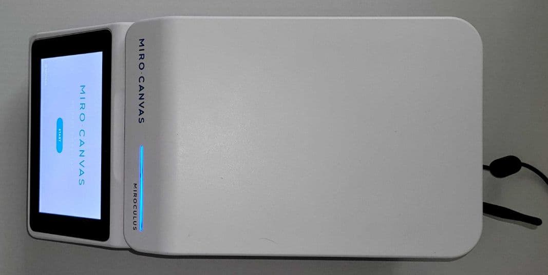
Click to zoom
Application Details
- Equipment Class
- DXX - Part 15 Low Power Communication Device Transmitter
- Date of Grant
- Sep 21, 2022
- Application Purpose
- Original Equipment
- Date of Application
- Sep 21, 2022
- Equipment Note
- digital microfluidics technology
- Frequency Range
- 13.56000000 - 13.56000000
- Company
- Miroculus, Inc.
- Country
- United States
Documents & Files
Document Text
Text extracted from the exhibit documents filed with the FCC. Open a document above to read the original.
Users Manual
User Guide Version 1.1 For research use only. Not for use in diagnostic procedures. DRAFT Contact Information and Legal .................................................................... 2 Section 1: General Information ....................................................................... 3 Section 2: Safety and Compliance ............................................................ 3 Section 3: Operating Conditions ................................................................ 4 Section 4: Components ......................................................................................... 4 Section 5: Installation ................................................................................................ 5 Section 6: Operation ................................................................................................... 6 Section 7: Maintenance & Troubleshooting ................................ 10 Revision History Version Revisions 1.1 Additional details concerning network connection requirements, reagent loading, and instrument leveling Table of Contents 1 • Miro Canvas • User Guide Contact Information Miroculus, Inc. 458 Brannan St. San Francisco, CA 94107 EMAIL: [email protected] PHONE: (415) 287-0505 WEB: miroculus.com Legal All Rights Reserved. No part of this publication may be reproduced, transcribed, or transmitted in any form, or by any means, electronic or mechanical, including photocopying and recording, for any purpose other than the purchaser’s use without written permission of Miroculus, Inc. 2 • Miro Canvas • User Guide Section 1 • General Information INTENDED USE The Miro Canvas is a benchtop digital microfluidics platform that delivers custom low-throughput workflow automation for academic, research, and pharmaceutical life science laboratories. The Miro Canvas is for Research Use Only (RUO). Section 2 • Safety and Compliance SAFETY STANDARDS Complies to: • UL STD 61010-1 • UL STD 61010-2-010 • EN 61010-1:2010+A1:2019 • IEC 61010-1:2010/AMD1:2016 • EN 61010-2-081:2020 • IEC 61010-2-081:2019 • EN 61010-2-010:2020 • IEC 61010-2-010:2019 Certified to: • CSA C22.2 STD # 61010-1-12 • CSA C22.2 STD # 61010-2-010 EMC STANDARDS The Miro Canvas has been tested and found to be in conformity with: • IEC/EN 61326-1:2021 • FCC 47 CFR Part 15, Subpart B - Verification • ICES-003 Issue 7:2020 • FCC 47 CFR Part 15, Subpart C - 15.225 • RSS-210, Issue 10, December 2019 • RSS-Gen, Issue 5, Amendment 1, March 2019 • ETSI EN 300 330 V2.1.1 • ETSI EN 300 328 V2.1.1 3 • Miro Canvas • User Guide 3 • Miro Canvas • User Guide European Conformity High Voltage UK Conformity Assessed Warning or Caution OPERATING PRECAUTIONS • Instrument is only to be operated by personnel who have read the User Guide in full and are using proper personal protective equipment. • Voltage applied during use. Follow all instructions when loading the instrument. • Use care when loading the cartridge on the instrument electrode board. • Handle liquids near the instrument with extreme caution. • Do not overfill reagent reservoirs. • Use the instrument only within the environmental conditions specified in this document. • Use only the power supply and cables provided with the instrument. • Use only the Wi-Fi antenna provided with the instrument. • Use the instrument in a dry environment, especially if synthetic materials are present (synthetic clothing, carpets, etc. may cause damaging electrostatic discharges). • Do not use this instrument in close proximity to sources of strong electromagnetic radiation, as these may interfere with proper operation. • Treat all samples as potentially biohazardous in accordance with your organization’s approved procedures. • Operate the instrument in a clean indoor area free of dust. • Do not operate the instrument if the internal components have been damaged or exposed to fluids. • Use only unexpired reagents and consumables. • Store Miro Dropgloss bottle upright and away from light. • Do not aliquot Miro Dropgloss. Leave in the original container. • Only write on cartridges with soft permanent or laboratory markers (Sharpie ® or similar). Do not apply pressure to the cartridge or cartridge film/label if annotating with markers. • Instrument electrode board is vulnerable to scratching. Do not slide the cartridge on the electrode board. Do not wipe the electrode board with any material. • Be aware of pinch points when opening and closing the instrument lid. FCC COMPLIANCE (FCC ID: 2A6E7MIROCANVAS10 CONTAINS FCC ID: VVXLM823) This device complies with part 15 of the FCC Rules. Operation is subject to the following two conditions: (1) This device may not cause harmful interference, and (2) this device must accept any interference received, including interference that may cause undesired operation. CAUTION: Changes or modifications not expressly approved by the party responsible for compliance could void the user’s authority to operate this equipment. If the device has removable antennas then a list of the antennas that may be used with the device must be included in the user manual. The list should identify the type of antenna, impedance (usually 50 ohms), and the maximum gain in dBi. SYMBOL TABLE INDUSTRY CANADA COMPLIANCE This device complies with Industry Canada licence-exempt RSS standard(s). Operation is subject to the following two conditions: (1) this device may not cause interference, and (2) this device must accept any interference, including interference that may cause undesired operation of the device. Cet appareil est conforme avec Industrie Canada exempts de licence standard RSS (s). Son fonctionnement est soumis aux deux conditions suivantes: (1) cet appareil ne doit pas provoquer d’interférences et (2) cet appareil doit accepter toute interférence, y compris celles pouvant causer un mauvais fonctionnement de l’appareil. Health Canada RF Exposure Warning Statement: This device complies with Health Canada’s Safety Code. The installer of this device shou…
Text truncated - open the document above for the full version.
External Photos
Miro-Canvas External Pictures <Front><Top> <Side> <Back><Bottom>
ID Label/Location Info
LABEL INFORMATION
Internal Photos
Internal Photographs July 6, 2022 Reference Main Board: -Rev. 3 version PCBA Electrode Board: -Rev. 5 version PCBA Manifold Board: -V1.0 version PCBA Main Board <Top> <Bottom> Electrode Board <Top> <Bottom> Manifold Board <Top><Bottom>
RF Exposure Info
© 2022 RF Exposure Lab, LLC This report shall not be reproduced except in full without the written approval of RF Exposure Lab, LLC. 802 N. Twin Oaks Valley Road, Suite 105 • San Marcos, CA 92069 • U.S.A. TEL (760) 471-2100 • FAX (760) 471-2121 http://www.rfexposurelab.com CERTIFICATE OF COMPLIANCE SAR EVALUATION Miroculus HQ Dates of Test: June 20-21, 2022 458 Brannan St. Test Report Number: SAR.20220620 San Francisco, CA 94107 Revision A This wireless mobile and/or portable device has been shown to be compliant for localized specific absorption rate (SAR) for uncontrolled environment/general exposure limits specified in ANSI/IEEE Std. C95.1-1992 and had been tested in accordance with the measurement procedures specified in IEEE 1528-2013 and IEC 62209-1528:2020 (See test report). I attest to the accuracy of the data. All measurements were performed by myself or were made under my supervision and are correct to the best of my knowledge and belief. I assume full responsibility for the completeness of these measurements and vouch for the qualifications of all persons taking them. RF Exposure Lab, LLC certifies that no party to this application is subject to a denial of Federal benefits that includes FCC benefits pursuant to Section 5301 of the Anti-Drug Abuse Act of 1988, 21 U.S.C. 853(a). Jay M. Moulton Vice President Testing Cert. # 2387.01 FCC ID: 2A6E7MIROCANVAS10 Model(s): Canvas 1.0 Test Sample: Engineering Unit Same as Production Serial Number: C122020102 Equipment Type: Wireless Device Classification: Portable Transmitter Next to Body TX Frequency Range: 2412 – 2462 MHz Frequency Tolerance: ± 2.5 ppm Maximum RF Output: 2450 MHz (b) – 19.00 dBm, 2450 MHz (g) – 17.00 dBm, 2450 MHz (n20) – 15.00 dBm, 2450 MHz (n40) – 15.00 dBm Conducted Signal Modulation: DSSS, OFDM Antenna Type: Internal Antenna Application Type: Certification FCC Rule Parts: Part 2, 15C, 15E KDB Test Methodology: KDB 447498 D01 v07, KDB 248227 v02r02 Maximum SAR Value: 0.26 W/kg Reported Separation Distance: 0 mm Report Number: SAR.20220620 © 2022 RF Exposure Lab, LLC Page 2 of 60 This report shall not be reproduced except in full without the written approval of RF Exposure Lab, LLC. Table of Contents 1. Introduction ................................................................................................................................................ 4 SAR Definition [5] .......................................................................................................................................... 5 2. SAR Measurement Setup .......................................................................................................................... 6 Robotic System ............................................................................................................................................. 6 System Hardware .......................................................................................................................................... 6 System Electronics ........................................................................................................................................ 6 Probe Measurement System ......................................................................................................................... 7 3. Probe and Dipole Calibration ................................................................................................................... 14 4. Phantom & Simulating Tissue Specifications ........................................................................................... 15 Head & Body Simulating Mixture Characterization ....................................................................................... 15 5. ANSI/IEEE C95.1 – 1992 RF Exposure Limits [2] .................................................................................... 16 Uncontrolled Environment ............................................................................................................................ 16 Controlled Environment ............................................................................................................................... 16 6. Measurement Uncertainty ........................................................................................................................ 17 7. System Validation .................................................................................................................................... 18 Tissue Verification ....................................................................................................................................... 18 Test System Verification .............................................................................................................................. 18 8. SAR Test Data Summary ......................................................................................................................... 19 Procedures Used To Establish Test Signal .................................................................................................. 19 Device Test Condition .................................................................................................................................. 19 SAR Data Summary – 2450 MHz Body 802.11b .......................................................................................... 22 9. Test Equipment List ................................................................................................................................. 23 10. Conclusion ........................................................................................................................................... 24 11. References .......................................................................................................................................... 25 Appendix A – System Validation Plots and Data .............................................................................................…
Text truncated - open the document above for the full version.
Test Report
www.nemko.com FCC 15C §15.225 & RSS-210.docx; Date: July 2020 Nemko USA Inc., a testing laboratory, is accredited by NVLAP. The tests included in this report are within the scope of this accreditation. O N E W O R L D O U R A P P R O V A L Test report 460572-4TRFWL Date of issue: March 30, 2022 Applicant: Miroculus, Inc Product: Micro Canvas Model: Canvas 1.0 Specifications: FCC 47 CFR Part 15, Subpart C – §15.225 Operation within the band 13.110-14.010 MHz RSS-210, Issue 10, December 2019 License-Exempt Radio Apparatus: Category I Equipment RSS-Gen, Issue 5, Amendment 1, March 2019 General Requirements for Compliance of Radio Apparatus Report reference ID: 460572-4TRFWL Page 2 of 25 Test location Company name Nemko USA, Inc. Address 2210 Faraday Ave, Suite 150 City Carlsbad Province California Postal code 92008 Country USA Telephone +1 760 444 3500 Website www.nemko.com FCC Site Number Test Firm Registration Number: 392943 Designation Number: US5058 ISED Test Site 2040B-3 Tested by Martha Espinoza, Wireless Test Engineer Reviewed by James Cunningham, EMC/MIL/WL Supervisor Review date March 31, 2022 Reviewer signature Limits of responsibility Note that the results contained in this report relate only to the items tested and were obtained in the period between the date of initial receipt of samples and the date of issue of the report. This test report has been completed in accordance with the requirements of ISO/IEC 17025. All results contain in this report are within Nemko USA’s ISO/IEC 17025 accreditation. This report must not be used by the client to claim product certification, approval, or endorsement by NVLAP, NIST, or any agency of the U.S. Government. Copyright notification Nemko USA Inc. authorizes the applicant to reproduce this report provided it is reproduced in its entirety and for use by the company’s employees only. Any use which a third party makes of this report, or any reliance on or decisions to be made based on it, are the responsibility of such third parties. Nemko USA Inc. accepts no responsibility for damages, if any, suffered by any third party as a result of decisions made or actions based on this report. © Nemko USA Inc. Report reference ID: 460572-4TRFWL Page 3 of 25 Table of contents Table of contents .......................................................................................................................................................................................................... 3 Section 1. Report summary ................................................................................................................................................................................. 4 1.1 Applicant and manufacturer .................................................................................................................................................................................... 4 1.2 Test specifications .................................................................................................................................................................................................... 4 1.3 Test methods ............................................................................................................................................................................................................ 4 1.4 Statement of compliance ......................................................................................................................................................................................... 4 1.5 Exclusions ................................................................................................................................................................................................................. 4 1.6 Test report revision history ...................................................................................................................................................................................... 4 Section 2. Summary of test results ....................................................................................................................................................................... 5 2.1 FCC Part 15 Subpart C, general requirements test results ........................................................................................................................................ 5 2.2 FCC Part 15 Subpart C, intentional radiators test results.......................................................................................................................................... 5 2.3 IC RSS-GEN, Issue 5 Amendment 1, test results ....................................................................................................................................................... 5 2.4 IC RSS-210, Issue 10, test results .............................................................................................................................................................................. 5 Section 3. Equipment under test (EUT) details ..................................................................................................................................................... 6 3.1 Sample information .................................................................................................................................................................................................. 6 3.2 EUT information ....................................................................................................................................................................................................... 6 3.3 Technical information .............................................................................................................................................................................................. 6 3.4 Product description and theory of operation ...........................................................…
Text truncated - open the document above for the full version.
Test Setup Photos
Report reference ID: 460572-5TRFWL (FCC 15.225 & RSS-210) Company Name: Miroculus, Inc. Model: Canvas 1.0 FCC ID: N/A IC ID: N/A Section 1. Test Setup Photos 1.1 Radiated emissions 0.009 to 30 MHz Figure 1.1-1 Figure 1.1-2 Report reference ID: 460572-5TRFWL (FCC 15.225 & RSS-210) Company Name: Miroculus, Inc. Model: Canvas 1.0 FCC ID: N/A IC ID: N/A 1.2 Radiated emissions 0.030 to 1 GHz Figure 1.2-1 Figure 1.2-2 Report reference ID: 460572-5TRFWL (FCC 15.225 & RSS-210) Company Name: Miroculus, Inc. Model: Canvas 1.0 FCC ID: N/A IC ID: N/A 1.3 Conducted Emissions (0.150 - 30 MHz) Figure 1.3-1 Figure 1.3-2 Report reference ID: 460572-5TRFWL (FCC 15.225 & RSS-210) Company Name: Miroculus, Inc. Model: Canvas 1.0 FCC ID: N/A IC ID: N/A 1.4 Frequency Stability Figure 1.4-1 Figure 1.4-2
Contact Information
Applicant
Alejandro Tocigl(CEO)
Test Firm
Nemko USA, Inc. - San Diego EMC DivisionJan Blomgren
[email protected]760-444-3500
Technical Specifications
| # | Rule Parts | Frequency Range | Power Output |
|---|---|---|---|
| 1 | 15C | 13.56 MHz - 13.56 MHz | - |