2A6EK-SC-6275S-001Cradlewise Smart Crib
Cradlewise Incorporated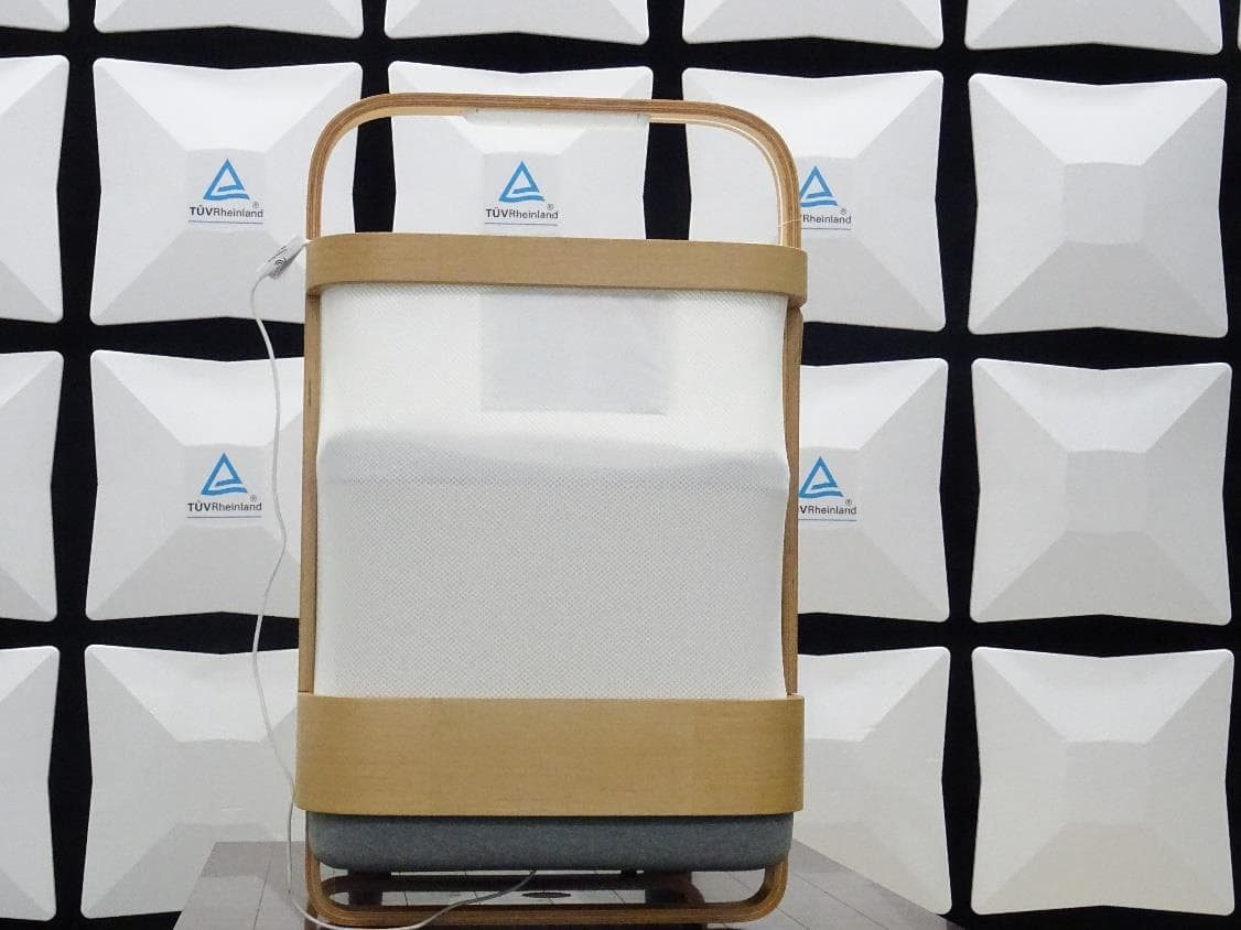
Click to zoom
Application Details
- Equipment Class
- NII - Unlicensed National Information Infrastructure TX
- Date of Grant
- Aug 17, 2022
- Application Purpose
- Original Equipment
- Date of Application
- Aug 15, 2022
- Equipment Note
- Cradlewise Smart Crib
- Frequency Range
- 5745.00000000 - 5825.00000000
- Company
- Cradlewise Incorporated
- Country
- United States
Documents & Files
Document Text
Text extracted from the exhibit documents filed with the FCC. Open a document above to read the original.
Users Manual
USER GUIDE Read all instructions BEFORE assembly of the product. Keep this guide for future use. All-in-One Smart Bassinet, Crib & Baby Monitor Birth to 24 Months 3 The beauty of Cradlewise is that it will be learning your baby’s schedule right along with you, and forecasting sleep and wake-up times. Customize the motion and sound settings to find the perfect sleep recipe that works for your little one. Inspired by the instinctual, calming way that a parent bounces their baby in their arms as they settle down to sleep, Cradlewise is the solution to giving natural care when you need a rest yourself. Because when babies get higher-quality sleep, it allows us to be well-rested and parent better. Sleep well! Congratulations! Thank you for choosing Cradlewise to be a part of your parenting journey—we’re thrilled to welcome you to our community. Sleep plays a salient role in a baby’s development, especially during the first two years. It has an overarching impact on everything from nutrition and brain development to your child’s mood and milestones. And when babies don’t sleep well, it affects parents too—their energy levels, relationships, and mental health. We set out to make the crib we wished we would have had as parents. Cradlewise isn’t just a piece of furniture but a helpful pair of hands. It allows babies to sleep better and longer. And in turn, it gives parents some peace of mind. We built a crib with the ability to detect your baby’s earliest wake-up signs and respond before they cry, creating a soothing environment where your little one can get a more continuous stretch of sleep. Co-Founder & CEO Welcome 4 What’s in This Guide? Welcome What’s in This Guide? What Makes Cradlewise the World’s Smartest Crib? What’s in the Box? Assembling Cradlewise Instructions for First-Time Setup Connected App for Monitoring GREENGUARD Gold Certified Winning With Cradlewise Customize Cradlewise for Your Baby 3 4 5 6 10 25 26 28 29 30 31 32 33 36 40 41 46 48 50 51 Personalize Sleep Tracks Graduating From Using Bounce How To Convert From Bassinet to Crib Mode How To Convert From Crib to Bassinet Mode Caring for Cradlewise Official Warnings FCC Compliance Caution 100-Night Trial Support 5 24-Month Sleep Companion Built-In Smart Monitor Cradlewise is a bassinet, crib, baby monitor, sound machine, and a sleep tracker, all rolled into one. It’s a complete sleep solution for newborns to toddlers. Keep a close eye on your little one using the connected app’s live video stream. Track your baby’s sleep and get insights for maintaining a consistent sleep routine. Customizable Sleep Tracks Choose from white, pink, and brown noise options selected to make your little one fall asleep faster (and sleep better). Noiseless Bouncing The whisper-quiet patented bouncing mechanism ensures you and your little one sleep peacefully without being disturbed. Caregiver Team Self-Learning Crib Grant access to grandparents, caretakers, or other loved ones within the Cradlewise App so they can stay connected to your baby. The monitor senses early wake-up signs and starts bouncing automatically to soothe your baby back to sleep. It learns and adapts to your little one’s unique sleep patterns. What Makes Cradlewise the World’s Smartest Crib? 6 What’s in the Box? TOP RAIL MONITOR BASSINET SUPPORT BASSINET MESH MESH TENSIONER CRIB MESH WOODEN SLAT CRIB BASE POWER CABLE MATTRESS MONITOR ARC 7 MATTRESS PACKMESH TENSIONER MONITOR ARC TOP RAIL USER GUIDE POWER ADAPTER MONITOR CABLE COVER 8 BASSINET BOARDWOODEN SLATS x3 BASSINET BRACKETS x4 CRIB BASE CRIB MESH BASSINET LEGS x2 9 BASSINET MESHFITTED SHEETS x2 SCREWDRIVER ALLEN KEY M6X12 BOLTS (C) x12 M6X16 BOLTS (E) x16 CAM LOCK NUTS (F) x9 M6X25 BOLTS (D) x4 CAM LOCK BOLTS (B) x9 WOOD DOWELS (A) x6 NOTE: SPARES INCLUDED 10 Pull the cardboard spacers from the gap between the wooden frame and legs. Place the crib base on the floor. 21 Lift the attached slat. 3 Assembling Cradlewise Assembling the crib base: 11 Screw the attached slat to the base with 3 (C) bolts using the Allen key. 4 Tighten the 3 (C) bolts using the Allen key’s longer arm. 5 Assembling the slats: 12 6 Screw 3 wooden slats into the crib base with 3 (C) bolts each (9 bolts total) using the Allen key. 7 Insert wooden dowels (A) halfway into the 3 slats. 8 Screw 5 cam lock bolts (B) in the top rail. 13 Affix the top rail in place by aligning the cam lock nuts (F) in the holes and rotating them clockwise, using the provided screwdriver. 10 Flip the top rail, match 2 cam lock bolts with the holes in the fixed slat and insert it. 9 Assembling the top rail: 14 Push the cord hanging from the monitor arc through the cavity on the top rail. Then, pull the line from the other end. 12 Screw 4 cam lock bolts (B) into the monitor arc. 11 Mounting the monitor arc: 15 14 Connect the monitor arc to the top rail by aligning the cam lock nuts (F) in the holes and rotating them clockwise, using the provided screwdriver. Raise the flap on the top rail to see the holes for cam lock nuts. 13 16 On the cord attached to the monitor arc, align the triangular markings facing the same side and connect the USB cord. (TIP: If the cords are not reaching each other, gently pull the bottom cord until the two ends meet.) If the cord is longer than required, fold it within the cavity. 15 Cover the USB cord with the monitor cable cover. Press firmly for a snug fit. (TIP: Insert the top end in first.) 16 17 Place the crib mesh inside the crib. Align the zip end of the mesh with the zipper beneath the flap on the top rail. Attaching the crib mesh: Attach the crib mesh to the top rail using the zipper. 17 18 18 19 Close the flap on the top rail.Place the mesh tensioner inside the crib. (TIP: You may have to use some force to ensure a snug fit). 20 19 21 Press down the mesh tensioner from all sides to ensure the crib mesh is uniformly taut. Screw the mesh tensioner to the crib base using 4 (D) bolts. (TIP: If you find it hard to engage the bolts, push the mesh t…
Text truncated - open the document above for the full version.
Block Diagram
OSC 37.4MHz and 32.768MHz
Cover Letter(s)
Authority to Act as Agent Date: 25/07/2022 TUV Rheinland of North America, Inc. 1279 Quarry Lane., Suite. A Pleasanton, CA 94566 To Whom It May Concern: I appoint Mr. Raghavendra Kulkarni to act as our agentin the preparation of this application for equipment certification. I certify that submitted documents properly describe the device or system for which equipment certification is sought. I also certify that each unit manufactured, imported or marketed, as defined in the FCC or Industry Canada’s regulations will have affixed to it a label identical to that submitted for approval with this application. For instances where our authorized agent signs the application for certification on our behalf, I acknowledge that all responsibility for complying with the terms and conditions for Certification, as specified by TUV Rheinland Group, still resides with____Cradlewise Inc 479,Jessie Street, San Francisco CA 94103 ForTCBapplications,Wecertifythatwearenotsubjecttodenialoffederalbenefits,thatincludesFCCbenefits, pursuanttoSection5301oftheAnti-DrugAbuseActof1988,21U.S.C.862.Further,noparty,asdefinedin47 CFR 1.2002 (b),to the application is subject to denialof federal benefits, that includes FCC benefits. Thank you, Agency Agreement Date:25/07/2022 Agreement is valid for 12 months from the above date.By: Radhika Patil (Signature) Co Founder & CEO 5109801716 On behalf of: Cradlewise Inc. www.cradlewise.com +1 510 980 1716 Cradlewise Inc. [email protected] Jessie Street,San Francisco, CA, 94103, USA
Cover Letter(s)
Confidentiality Letter Date:July 25, 2022 Subject: Confidentiality Request for Cradlewise FCC ID: 2A6EK-SC-6275S-001 Pursuant to FCC 47 CRF 0.457(d) and 0.459 and IC RSP-100, Section 10, the applicant requests that a part of the subject FCC/IC application be held confidential. Type of Confidentiality RequestedExhibit ☒ Short Term☐ PermanentBlock Diagrams ☒ Short Term☐ PermanentExternal Photos ☒ Short Term☐ PermanentInternal Photos ☒ Short Term☐ Permanent Operation Description/Theory of Operation /NII software security attestation ☐ Short Term☒ PermanentPart List/Tune-Up Procedure ☐ Short Term☒ PermanentSchematics ☐ Short Term☒ PermanentBill of materials (BOM) ☒ Short Term☐ PermanentTest Setup Photos ☐ Short Term☐ PermanentUser’s Manual Cradlewise has spent substantial effort in developing this product and it is one of the first of its kind in industry. Having the subject information easily available to "competition" would negate the advantage they have achieved by developing this product. Not protecting the details of the design will result in financial hardship. Permanent Confidentiality: The applicant requests the exhibits listed above as permanently confidential be permanently withheld from public review due to materials that contain trade secrets and proprietary information not customarily released to the public. Short-Term Confidentiality: The applicant requests the exhibits selected above as short term confidential be withheld from public view for a period of180days from the date of theGrant of Equipment Authorization and prior to marketing. This is to avoid premature release of sensitive information prior to marketing or release of the product to the public. Applicant is also aware that they are responsible to notify TUV Rheinland in the event information regarding the product or the product is made available to the public. TUV Rheinland will then release the documents listed above for public disclosure pursuant toFCC Public Notice DA 04-1705. Sincerely, Radhika Patil/ Co Founder & CEO www.cradlewise.com+1 510 980 1716 Cradlewise Inc. [email protected] Jessie Street, SanFrancisco, CA, 94103, USA ☐
Cover Letter(s)
Date: July 11, 2022 Justification for Re-use of Radio Test Results We,Cradlewise Inc,believe that the conducted signaltest data on original reports provided by the Askey Computer Corp (WIFI+BT Combo Module, FCC ID:H8N-AP6275S approved on July 7, 2021) can be re-used for the following reasons: 1.Applicant has built in the radio module according to the specific radio module integration guides. 2.No changes have been made on radio module, only the WIFI+BT module antennas have been changed. 3.Re-test the conducted power for spot check verification, the radiated spurious emission and co-located emission, and re-evaluated the RF Exposure. By Radhika Patil Title: CEO On behalf of Cradlewise Inc
External Photos
Produkte Products www.tuv.com External Photos Reference Test Report No: ULR-TC568822300000062F/63F/64F Seite 1 von 4 Page 1 of 4 External Photos EUT Front View EUT Left View Produkte Products www.tuv.com External Photos Reference Test Report No: ULR-TC568822300000062F/63F/64F Seite 2 von 4 Page 2 of 4 EUT Right View EUT Top View Produkte Products www.tuv.com External Photos Reference Test Report No: ULR-TC568822300000062F/63F/64F Seite 3 von 4 Page 3 of 4 EUT Dimensional view EUT Dimension view Produkte Products www.tuv.com External Photos Reference Test Report No: ULR-TC568822300000062F/63F/64F Seite 4 von 4 Page 4 of 4 EUT Dimension view
ID Label/Location Info
DETAIL B SCALE 0.75 B 1 1 2 2 3 3 4 4 5 5 6 6 AA BB CC DD PROJECT: MATERIAL: WEIGHT:SHEET SIZE:SHEET : MANUFACTURING PROCESS: Pankaj Maurya 08-10-2021 DRAWN DATE CHECKEDAPPROVED PART CODE:REVISION NUMBER: PART NAME: CRADLEWISE INC ALL INTELLECTUAL PROPERTY RIGHTS, INCLUDING BUT NOT LIMITED TO COPYRIGHT, APPLYING TO THIS DRAWING AND THE INFORMATION CONTAINED THEREIN VEST SOLELY AND EXCLUSIVELY WITH CRADLEWISE INC. NO PART OF THIS DRAWING MAY BE COPIED OR REPRODUCED, EITHER IN PART OR IN FULL BY ANY MEANS, WHETHER MECHANICAL OR ELECTRONIC, WITHOUT PRIOR WRITTEN PERMISSION OF THE AUTHORIZED SIGNATORY OF CRADLEWISE INC. CRADLEWISE INC RESERVES ALL RIGHTS TO DEAL WITH VIOLATION OF THIS CLAUSE IN ACCORDANCE WITH APPLICABLE LAWS. R E M O V E B U R R S R E M O V E A L L S H A R P E D G E S T O R 0 . 5 O R A S S P E C I F I E D R E M O V E S P A T T E R S R E M O V E F L A S H E S T O L E R A N C E S A S P E R I S O 2 7 6 8 N O T T O S C A L E A L L D I M E N S I O N A R E I N M M P A R T N U M B E R : C A B L E L A B E L S P O S I T I O N A S S E M B L Y 0.184 kg A3 1 /1 CABLE LABELS POSITION ASSEMBLY1.3 STATUS: NOTE: 1. MATERIAL TO BE FREE OF DEFECTS, SCRATCHES, DINGS ETC. 2. FOR FURTHER DETAIL & DIMENSION, REFER 3D FILE 50.00 50.00 50.00 REVISION HISTORY REVDESCRIPTIONDATE 1.1 FCC ID CHANGED12-07-2022 1.3FCC LABEL UPDATED14-07-2022 1.3FCC LABEL UPDATED11-08-2022 1.3
ID Label/Location Info
FCC ID: 2A6EK-SC-6275S-001 This device complies with Part 15 of the FCC Rules. Operation is subject to the following two conditions: (1) this device may not cause harmful interference, and (2) this device must accept any interference received, including interference that may cause undesired operation. FCC ID: 2A6EK-SC-6275S-001 This device complies with Part 15 of the FCC Rules. Operation is subject to the following two conditions: (1) this device may not cause harmful interference, and (2) this device must accept any interference received, including interference that may cause undesired operation.
Internal Photos
Produkte Products www.tuv.com Internal Photos Reference Test Report No: ULR-TC568822300000062F/63F/64F Seite 1 von 13 Page 1 of 13 Internal Photos Photo 1: Bassinet mode with mattress Photo 2: Bassinet mode without mattress Produkte Products www.tuv.com Internal Photos Reference Test Report No: ULR-TC568822300000062F/63F/64F Seite 2 von 13 Page 2 of 13 Photo 3: Bassinet mode without bassinet mesh Photo 4: Crib mode Produkte Products www.tuv.com Internal Photos Reference Test Report No: ULR-TC568822300000062F/63F/64F Seite 3 von 13 Page 3 of 13 Photo 5: Crib mode without mattress Photo 6: Crib mode Produkte Products www.tuv.com Internal Photos Reference Test Report No: ULR-TC568822300000062F/63F/64F Seite 4 von 13 Page 4 of 13 Photo 7: Crib mode without mattress and without mesh tensioner Photo 8: Crib without mesh Produkte Products www.tuv.com Internal Photos Reference Test Report No: ULR-TC568822300000062F/63F/64F Seite 5 von 13 Page 5 of 13 Photo 9: Monitor arc Photo 10: Cradle without mechanism cover Produkte Products www.tuv.com Internal Photos Reference Test Report No: ULR-TC568822300000062F/63F/64F Seite 6 von 13 Page 6 of 13 Photo 11: Power board and speaker used in the cradle Photo 12: Monitor ARC dimensional View Produkte Products www.tuv.com Internal Photos Reference Test Report No: ULR-TC568822300000062F/63F/64F Seite 7 von 13 Page 7 of 13 Photo 13: Monitor ARC dimensional View Photo 14: Monitor arc with monitor cover open Produkte Products www.tuv.com Internal Photos Reference Test Report No: ULR-TC568822300000062F/63F/64F Seite 8 von 13 Page 8 of 13 Photo 15: Monitor cover and camera board Photo 16: Camera board Produkte Products www.tuv.com Internal Photos Reference Test Report No: ULR-TC568822300000062F/63F/64F Seite 9 von 13 Page 9 of 13 Photo 17: Camera board Photo 18: Camera board Produkte Products www.tuv.com Internal Photos Reference Test Report No: ULR-TC568822300000062F/63F/64F Seite 10 von 13 Page 10 of 13 Photo 19: Power board Photo 20: Power board bottom Produkte Products www.tuv.com Internal Photos Reference Test Report No: ULR-TC568822300000062F/63F/64F Seite 11 von 13 Page 11 of 13 Photo 21: Power board dimensional View Photo 22: Power board dimensional View Produkte Products www.tuv.com Internal Photos Reference Test Report No: ULR-TC568822300000062F/63F/64F Seite 12 von 13 Page 12 of 13 Photo 23: Compute board with dimensioanl view Photo 24: Compute board with dimensioanl view Produkte Products www.tuv.com Internal Photos Reference Test Report No: ULR-TC568822300000062F/63F/64F Seite 13 von 13 Page 13 of 13 Photo 25: Wireless module without shield Photo 26: Wireless module with shield open
RF Exposure Info
Produkte Products www.tuv.com RF Exposure Reference test Report No: ULR-TC568822300000062F/63F/64F Seite 1 von 2 Page 1 of 2 1 Maximum Permissible Exposure 1.1 RF Exposure Compliance Requirement The limit for Maximum Permissible Exposure (MPE) specified in FCC 1.1310 is followed. The gain of the antennas used in the product is extracted from the Antenna data sheets provided and also the maximum total power input to the antenna is measured. Through the Friis transmission formula and the maximum gain of the antenna, we can calculate the distance, away from the product, where the limit of MPE is reached. Although the Friis Transmission formula is far field assumption, the calculated result of that is an over-prediction for near field power density. It is taken as worst case to specify the safety range. 1.2 RF Exposure Limits: 1.2.1 For FCC 1. According to FCC Part 1 Subpart I 1.1310: The criteria listed in the following table shall be used to evaluate the environmental impact of the human exposure to radio-frequency (RF) radiation as specified in 1.1307 (b) showed in Table 1. F or ƒ = Frequency in MHz Friss Formula Friss Transmission Formula: Pd = (Pout * G) / (4*pi*r²) Where Pd = power density in mW/cm² Pout = output power to antenna in mW G = gain of antenna in linear scale Pi = 3.1416 R = Distance between observation point and the center of radiator in cm If we know the maximum gain of the antenna and the total output power to the antenna, through calculation, we will know MPE value at distance 20cm. Produkte Products www.tuv.com RF Exposure Reference test Report No: ULR-TC568822300000062F/63F/64F Seite 2 von 2 Page 2 of 2 Test Results: Manufacturer has declared the tune-up value as ±1 dB is considered in MPE calculation. Antenna: Molex 2042811100 balanced, dipole-type antenna Antenna Gain: 2.0dBi for 2.4GHz & 3.3dBi for 5GHz Protocol Frequen cy (MHz) Maximum measured RF output power at antenna terminal (dBm) Tune-up tolerance (dB) Max power Including tune-up tolerance * (mW) Min Separation distance (CM) Power Density (Pd) (mW/cm²) FCC Limit (mW/cm2) 802.11b/g/n/ax 2462 16.64 ±1 58.0764 20 0.0183 1 Bluetooth Low Energy 2440 -11.84 ±1 0.0877 20 0.00003 1 Bluetooth 2402 -11.57 ±1 0.0827 20 0.00003 1 802.11a/n/ac/ax 5755 17.56 ±1 71.7794 20 0.03051 1 Note: Maximum conducted output power taken from test Reports: ULR-TC568822300000062F/63F/64F Test Results for Maximum Permissible Exposure for Simultaneous operating mode of Wi-Fi and BLE RF Protocol Calculated MPE (mW) Final MPE((mW/cm 2 ) Limit (mW/cm 2 ) Wi-Fi 2.4 GHz + BLE (0.0183)+(0.00003) 0.01833 <1 Wi-Fi 2.4 GHz + BT (0.0183)+(0.00003) 0.01833 <1 1.3 Conclusion The Power density of the EUT is less than defined limit as shown above, hence EUT is exempted from routine SAR.
Test Report
MRT Technology (Suzhou) Co., Ltd Report No.: 2104RSU079-U5 Phone: +86-512-66308358 Report Version: V01 Web: www.mrt-cert.com Issue Date: 07-01-2021 Page Number: 1 of 371 FCC ID: H8N-AP6275S IC: 1353A-AP6275S Applicant: Askey Computer Corporation Application Type: Certification Product: WIFI+BT Combo Module Model No.: AP6275S Brand Name: ASKEY FCC Classification: Unlicensed National Information Infrastructure (NII) FCC Rule Part(s): Part15 Subpart E (Section 15.407) ISED Rule (s): RSS-247 Issue 2, RSS-GEN Issue 5 Test Procedure(s): ANSI C63.10-2013, KDB 789033 D02v02r01 KDB 662911 D01v02r01 Test Date: May 28 ~ June 28, 2021 Reviewed By: Kevin Guo Approved By: Robin Wu MEASUREMENT REPORT FCC PART 15.247 / ISED RSS-247 WLAN The test results relate only to the samples tested. This equipment has been shown to be capable of compliance with the applicable technical standards as indicated in the measurement report and was tested in accordance with the measurement procedures specified in KDB 789033 D02v02r01. Test results reported herein relate only to the item(s) tested. The test report shall not be reproduced except in full without the written approval of MRT Technology (Suzhou) Co., Ltd. Report No.: 2104RSU079-U5 Page Number: 2 of 371 Revision History Report No. Version Description Issue Date Note 2104RSU079-U5 Rev. 01 Initial Report 07-01-2021 Valid Report No.: 2104RSU079-U5 Page Number: 3 of 371 CONTENTS Description Page 1. General Information ............................................................................................................... 6 1.1. Applicant ....................................................................................................................... 6 1.2. Manufacturer ................................................................................................................ 6 1.3. Testing Facility .............................................................................................................. 6 2. PRODUCT INFORMATION ..................................................................................................... 7 2.1. Equipment Description .................................................................................................. 7 2.2. Product Specification Subjective to this Report ............................................................. 7 2.3. Working Frequencies for this report .............................................................................. 8 2.4. Description of Available Antennas ................................................................................. 9 2.5. Test Mode .................................................................................................................. 10 2.6. Configuration of Test System ...................................................................................... 10 2.7. Test System Details ..................................................................................................... 11 2.8. Description of Test Software ........................................................................................ 11 2.9. Test Environment Condition ......................................................................................... 11 2.10. Duty Cycle ................................................................................................................... 11 2.11. EMI Suppression Device(s)/Modifications ................................................................... 13 2.12. Labeling Requirements ............................................................................................... 13 3. ANTENNA REQUIREMENTS ................................................................................................ 14 4. TEST EQUIPMENT CALIBRATION DATE ............................................................................ 15 5. MEASUREMENT UNCERTAINTY ......................................................................................... 19 6. TEST RESULT ...................................................................................................................... 20 6.1. Summary .................................................................................................................... 20 6.2. Occupied Bandwidth Measurement ............................................................................ 21 6.2.1. Test Limit .................................................................................................................... 21 6.2.2. Test Procedure used ................................................................................................... 21 6.2.3. Test Setting ................................................................................................................. 21 6.2.4. Test Setup .................................................................................................................. 22 6.2.5. Test Result .................................................................................................................. 23 6.3. 6dB Bandwidth Measurement ..................................................................................... 42 6.3.1. Test Limit .................................................................................................................... 42 6.3.2. Test Procedure used ................................................................................................... 42 6.3.3. Test Setting ................................................................................................................. 42 6.3.4. Test Setup .................................................................................................................. 42 6.3.5. Test Result .................................................................................................................. 43 Report No.: 2104RSU079-U5 Page Number: 4 of 371 6.4. Output Power Measurement ...................................................................................…
Text truncated - open the document above for the full version.
Test Report
Report No.: 2104RSU079-U5 Page Number: 38 of 371 802.11ax-HE20 26dB Bandwidth - Ant 0 / Ant 0 + 1 Channel 36 (5180MHz) Channel 44 (5220MHz) Channel 48 (5240MHz) Channel 52 (5260MHz) Channel 60 (5300MHz) Channel 64 (5320MHz) Channel 100 (5500MHz) Channel 116 (5580MHz) Report No.: 2104RSU079-U5 Page Number: 39 of 371 802.11ax-HE20 26dB Bandwidth - Ant 0 / Ant 0 + 1 Channel 140 (5700MHz) Channel 144 (5720MHz) Channel 149 (5745MHz) Channel 157 (5785MHz) Channel 165 (5825MHz) Report No.: 2104RSU079-U5 Page Number: 40 of 371 802.11ax-HE40 26dB Bandwidth - Ant 0 / Ant 0 + 1 Channel 38 (5190MHz) Channel 46 (5230MHz) Channel 54 (5270MHz) Channel 62 (5310MHz) Channel 102 (5510MHz) Channel 110 (5550MHz) Channel 134 (5670MHz) Channel 142 (5710MHz) Report No.: 2104RSU079-U5 Page Number: 41 of 371 802.11ax-HE40 26dB Bandwidth - Ant 0 / Ant 0 + 1 Channel 151 (5755MHz) Channel 159 (5795MHz) 802.11ax-HE80 26dB Bandwidth - Ant 0 / Ant 0 + 1 Channel 42 (5210MHz) Channel 58 (5290MHz) Channel 106 (5530MHz) Channel 122 (5610MHz) Channel 138 (5690MHz) Channel 155 (5775MHz) Report No.: 2104RSU079-U5 Page Number: 42 of 371 6.3. 6dB Bandwidth Measurement 6.3.1.Test Limit The minimum 6dBbandwidth shall be at least 500 kHz. 6.3.2.Test Procedure used KDB 789033 D02v02r01 - Section C.2 6.3.3.Test Setting 1. Set center frequency to the nominal EUT channel center frequency. 2. RBW = 100 kHz. 3. VBW≥ 3 × RBW. 4. Detector = Peak. 5. Trace mode = max hold. 6. Sweep = auto couple. 7. Allow the trace to stabilize. 8. Measure the maximum width of the emission that is constrained by the frequencies associated with the two outermost amplitude points (upper and lower frequencies) that are attenuated by 6 dB relative to the maximum level measured in the fundamental emission. 6.3.4.Test Setup Report No.: 2104RSU079-U5 Page Number: 43 of 371 6.3.5.Test Result Test Site WZ-TR3 Test Engineer Luis Yang Test Date 2021/06/03 Test Mode Data Rate/ MCS Channel No. Frequency (MHz) 6dB Bandwidth (MHz) Limit (MHz) Result Ant 0 / Ant 0 + 1 802.11a 6Mbps 149 5745 16.31 ≥ 0.5 Pass 802.11a 6Mbps 157 5785 15.32 ≥ 0.5 Pass 802.11a 6Mbps 165 5825 16.35 ≥ 0.5 Pass 802.11n-HT20 MCS0 149 5745 17.18 ≥ 0.5 Pass 802.11n-HT20 MCS0 157 5785 17.57 ≥ 0.5 Pass 802.11n-HT20 MCS0 165 5825 17.53 ≥ 0.5 Pass 802.11n-HT40 MCS0 151 5755 36.33 ≥ 0.5 Pass 802.11n-HT40 MCS0 159 5795 35.40 ≥ 0.5 Pass 802.11ac-VHT20 MCS0 149 5745 17.58 ≥ 0.5 Pass 802.11ac-VHT20 MCS0 157 5785 17.60 ≥ 0.5 Pass 802.11ac-VHT20 MCS0 165 5825 17.59 ≥ 0.5 Pass 802.11ac-VHT40 MCS0 151 5755 35.61 ≥ 0.5 Pass 802.11ac-VHT40 MCS0 159 5795 35.39 ≥ 0.5 Pass 802.11ac-VHT80 MCS0 155 5775 73.87 ≥ 0.5 Pass 802.11ax-HE20 MCS0 149 5745 18.83 ≥ 0.5 Pass 802.11ax-HE20 MCS0 157 5785 13.93 ≥ 0.5 Pass 802.11ax-HE20 MCS0 165 5825 17.25 ≥ 0.5 Pass 802.11ax-HE40 MCS0 151 5755 37.11 ≥ 0.5 Pass 802.11ax-HE40 MCS0 159 5795 37.13 ≥ 0.5 Pass 802.11ax-HE80 MCS0 155 5775 77.19 ≥ 0.5 Pass Report No.: 2104RSU079-U5 Page Number: 44 of 371 802.11a 6dB Bandwidth - Ant 0 / Ant 0 + 1 Channel 149 (5745MHz) Channel 157 (5785MHz) Channel 165 (5825MHz) 802.11n-HT20 6dB Bandwidth - Ant 0 / Ant 0 + 1 Channel 149 (5745MHz) Channel 157 (5785MHz) Channel 165 (5825MHz) Report No.: 2104RSU079-U5 Page Number: 45 of 371 802.11n-HT40 6dB Bandwidth - Ant 0 / Ant 0 + 1 Channel 151 (5755MHz) Channel 159 (5795MHz) 802.11ac-VHT20 6dB Bandwidth - Ant 0 / Ant 0 + 1 Channel 149 (5745MHz) Channel 157 (5785MHz) Channel 165 (5825MHz) Report No.: 2104RSU079-U5 Page Number: 46 of 371 802.11ac-VHT40 6dB Bandwidth - Ant 0 / Ant 0 + 1 Channel 151 (5755MHz) Channel 159 (5795MHz) 802.11ac-VHT80 6dB Bandwidth - Ant 0 / Ant 0 + 1 Channel 155 (5775MHz) Report No.: 2104RSU079-U5 Page Number: 47 of 371 802.11ax-HE20 6dB Bandwidth - Ant 0 / Ant 0 + 1 Channel 149 (5745MHz) Channel 157 (5785MHz) Channel 165 (5825MHz) 802.11ax-HE40 6dB Bandwidth - Ant 0 / Ant 0 + 1 Channel 151 (5755MHz) Channel 159 (5795MHz) Report No.: 2104RSU079-U5 Page Number: 48 of 371 802.11ax-HE80 6dB Bandwidth - Ant 0 / Ant 0 + 1 Channel 155 (5775MHz) Report No.: 2104RSU079-U5 Page Number: 49 of 371 6.4. Output Power Measurement 6.4.1.Test Limit FCC Limit For client devices in the 5.15-5.25 GHz band, the maximum conducted output power over the frequency band of operation shall not exceed 250 mW provided the maximum antenna gain does not exceed 6 dBi. For the 5.25-5.35 GHz and 5.47-5.725 GHz bands, the maximum conducted output power over the frequency bands of operation shall not exceed the lesser of 250 mW or 11 dBm + 10 log B, where B is the 26 dB emission bandwidth in megahertz. For the band 5.725-5.85 GHz, the maximum conducted output power over the frequency band of operation shall not exceed 1 W (30dBm). If transmitting antennas of directional gain greater than 6dBi are used, the maximum conducted output power shall be reduced by the amount in dB that the directional gain of the antenna exceeds 6dBi. ISED Limit For the band 5.15-5.25 GHz, the maximum e.i.r.p. shall not exceed 200 mW (23.01dBm) or 10 + 10 log 10 B, dBm, whichever power is less. B is the 99% emission bandwidth in MHz. For the 5.25-5.35 GHz and 5.47-5.725 GHz bands, the maximum conducted output power shall not exceed 250 mW (23.98dBm) or 11 + 10 log 10 B, dBm, whichever power is less. The maximum e.i.r.p. shall not exceed 1.0 W (30dBm) or 17 + 10 log 10 B, dBm, whichever power is less. B is the 99% emission bandwidth in MHz. For the 5.725-5.85 GHz band, the maximum conducted output power shall not exceed 1 W. If transmitting antennas of directional gain greater than 6 dBi are us…
Text truncated - open the document above for the full version.
Contact Information
Applicant
Radhika Patil
Technical Contact
Cradlewise IncorporatedRachit Rawat
[email protected]7338548001
Ginserve (Global Incubation Services) · Bengaluru · India
Test Firm
TUV Rheinland (India) Pvt. Ltd.B R Guruprasad
[email protected]+91 8046498000
Technical Specifications
| # | Rule Parts | Frequency Range | Power Output |
|---|---|---|---|
| 4 | 15E | 5.75 GHz - 5.83 GHz | 84.90 mW |
Other Applications from Cradlewise Incorporated
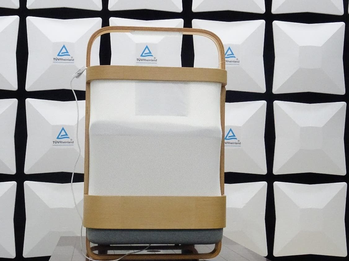
2A6EK-SC-6275S-002
Apr 17, 2023Cradlewise Smart Crib
Equipment Class
NII - Unlicensed National Information Infrastructure TX